Page 189 of 3189
Tool number
Tool nameDescription
KV101056S0
Ring gear stopper
1 KV10105630
Adapter
2 KV10105610
Plate
NT617
Preventing crankshaft from rotating
a: 3 (0.12)
b: 6.4 (0.252)
c: 2.8 (0.110)
d: 6.6 (0.260)
e: 107 (4.21)
f: 14 (0.55)
g: 20 (0.79)
h: 14 (0.55) dia.
Unit: mm (in)
KV101151S0
Lifter stopper set
1 KV10115110
Camshaft pliers
2 KV10115120
Lifter stopper
NT041
Changing shims
ST16610001
Pilot bushing puller
NT045
Removing crankshaft pilot bushing
KV10111100
Seal cutter
NT046
Removing steel oil pan and rear timing chain
case
WS39930000
Tube presser
NT052
Pressing the tube of liquid gasket
KV10112100
Angle wrench
NT014
Tightening bolts for bearing cap, cylinder
head, etc.
KV10109300
Pulley holder
NT628
a: 68 mm (2.68 in)
b: 8 mm (0.31 in) dia.
GI
MA
LC
EC
FE
CL
MT
AT
AX
SU
BR
ST
RS
BT
HA
SC
EL
IDX
PREPARATIONYD
Special Service Tools (Cont’d)
EM-5
Page 192 of 3189

NJEM0051
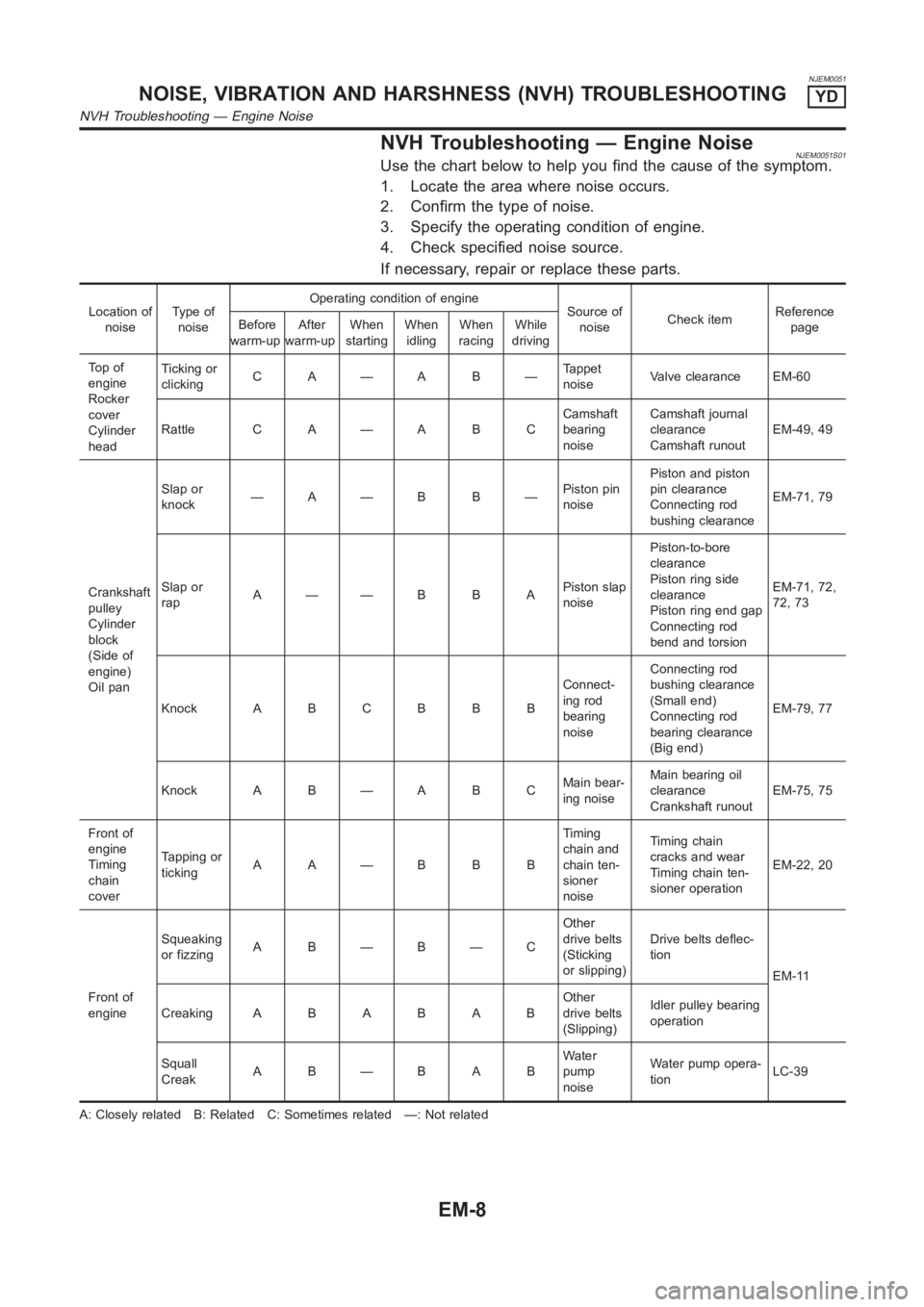
NVH Troubleshooting — Engine NoiseNJEM0051S01Use the chart below to help you find the cause of the symptom.
1. Locate the area where noise occurs.
2. Confirm the type of noise.
3. Specify the operating condition of engine.
4. Check specified noise source.
If necessary, repair or replace these parts.
Location of
noiseTy p e o f
noiseOperating condition of engine
Source of
noiseCheck itemReference
page Before
warm-upAfter
warm-upWhen
startingWhen
idlingWhen
racingWhile
driving
To p o f
engine
Rocker
cover
Cylinder
headTicking or
clickingC A—A B—Tappet
noiseValve clearance EM-60
Rattle C A — A B CCamshaft
bearing
noiseCamshaft journal
clearance
Camshaft runoutEM-49, 49
Crankshaft
pulley
Cylinder
block
(Side of
engine)
Oil panSlap or
knock—A—B B—Piston pin
noisePiston and piston
pin clearance
Connecting rod
bushing clearanceEM-71, 79
Slap or
rapA——B B APiston slap
noisePiston-to-bore
clearance
Piston ring side
clearance
Piston ring end gap
Connecting rod
bend and torsionEM-71, 72,
72, 73
Knock A B C B B BConnect-
ing rod
bearing
noiseConnecting rod
bushing clearance
(Small end)
Connecting rod
bearing clearance
(Big end)EM-79, 77
Knock A B — A B CMain bear-
ing noiseMain bearing oil
clearance
Crankshaft runoutEM-75, 75
Front of
engine
Timing
chain
coverTapping or
tickingAA—BBBTiming
chain and
chain ten-
sioner
noiseTiming chain
cracks and wear
Timing chain ten-
sioner operationEM-22, 20
Front of
engineSqueaking
or fizzingA B—B—COther
drive belts
(Sticking
or slipping)Drive belts deflec-
tion
EM-11
CreakingABABABOther
drive belts
(Slipping)Idler pulley bearing
operation
Squall
CreakAB—BABWater
pump
noiseWater pump opera-
tionLC-39
A: Closely related B: Related C: Sometimes related —: Not related
NOISE, VIBRATION AND HARSHNESS (NVH) TROUBLESHOOTINGYD
NVH Troubleshooting — Engine Noise
EM-8
Page 204 of 3189

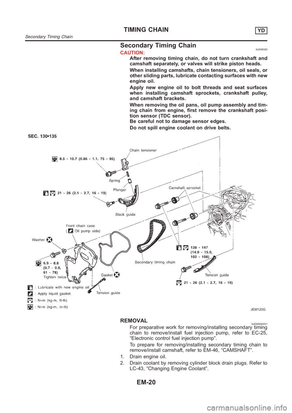
Secondary Timing ChainNJEM0093CAUTION:
After removing timing chain, do not turn crankshaft and
camshaft separately, or valves will strike piston heads.
When installing camshafts, chain tensioners, oil seals, or
other sliding parts, lubricate contacting surfaces with new
engine oil.
Apply new engine oil to bolt threads and seat surfaces
when installing camshaft sprockets, crankshaft pulley,
and camshaft brackets.
When removing the oil pans, oil pump assembly and tim-
ing chain from engine, first remove the crankshaft posi-
tion sensor (TDC sensor).
Be careful not to damage sensor edges.
Do not spill engine coolant on drive belts.
JEM120G
REMOVALNJEM0093S01For preparative work for removing/installing secondary timing
chain to remove/install fuel injection pump, refer to EC-25,
“Electronic control fuel injection pump”.
To prepare for removing/installing secondary timing chain to
remove/install camshaft, refer to EM-46, “CAMSHAFT”.
1. Drain engine oil.
2. Drain coolant by removing cylinder block drain plugs. Refer to
LC-43, “Changing Engine Coolant”.
TIMING CHAINYD
Secondary Timing Chain
EM-20
Page 205 of 3189

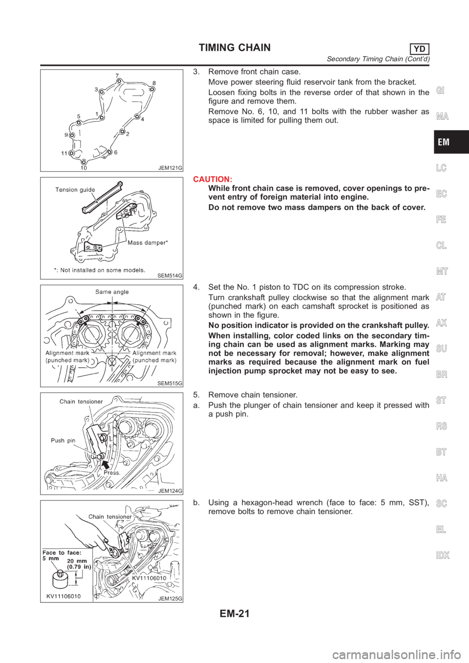
JEM121G
3. Remove front chain case.
Move power steering fluid reservoir tank from the bracket.
Loosen fixing bolts in the reverse order of that shown in the
figure and remove them.
Remove No. 6, 10, and 11 bolts with the rubber washer as
space is limited for pulling them out.
SEM514G
CAUTION:
While front chain case is removed, cover openings to pre-
vent entry of foreign material into engine.
Do not remove two mass dampers on the back of cover.
SEM515G
4. Set the No. 1 piston to TDC on its compression stroke.
Turn crankshaft pulley clockwise so that the alignment mark
(punched mark) on each camshaft sprocket is positioned as
shown in the figure.
No position indicator is provided on the crankshaft pulley.
When installing, color coded links on the secondary tim-
ing chain can be used as alignment marks. Marking may
not be necessary for removal; however, make alignment
marks as required because the alignment mark on fuel
injection pump sprocket may not be easy to see.
JEM124G
5. Remove chain tensioner.
a. Push the plunger of chain tensioner and keep it pressed with
a push pin.
JEM125G
b. Using a hexagon-head wrench (face to face: 5 mm, SST),
remove bolts to remove chain tensioner.
GI
MA
LC
EC
FE
CL
MT
AT
AX
SU
BR
ST
RS
BT
HA
SC
EL
IDX
TIMING CHAINYD
Secondary Timing Chain (Cont’d)
EM-21
Page 206 of 3189
JEM126G
6. Remove timing chain slack guide.
Using a hexagon-head wrench (face to face: 6 mm, SST),
remove bolt to remove timing chain slack guide.
JEM127G
7. Remove timing chain tension guide.
8. Remove secondary timing chain.
Timing chain alone can be removed without removing sprock-
ets.
SEM885F
INSPECTIONNJEM0093S02Check for cracks and excessive wear at roller links. Replace
chain if necessary.
JEM128G
INSTALLATIONNJEM0093S031. Install secondary timing chain.
When installing, match the alignment marks on sprockets with
color coded alignment marks (colored links) on the chain.
2. Install timing chain tension guide.
The upper bolt has a longer shank than the lower bolt.
TIMING CHAINYD
Secondary Timing Chain (Cont’d)
EM-22
Page 207 of 3189

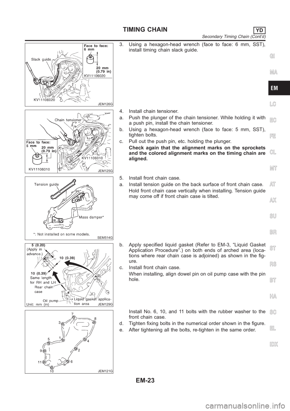
JEM126G
3. Using a hexagon-head wrench (face to face: 6 mm, SST),
install timing chain slack guide.
JEM125G
4. Install chain tensioner.
a. Push the plunger of the chain tensioner. While holding it with
a push pin, install the chain tensioner.
b. Using a hexagon-head wrench (face to face: 5 mm, SST),
tighten bolts.
c. Pull out the push pin, etc. holding the plunger.
Check again that the alignment marks on the sprockets
and the colored alignment marks on the timing chain are
aligned.
SEM514G
5. Install front chain case.
a. Install tension guide on the back surface of front chain case.
Hold front chain case vertically when installing. Tension guide
may come off if front chain case is tilted.
JEM129G
b. Apply specified liquid gasket (Refer to EM-3, “Liquid Gasket
Application Procedure”.) on both ends of arched area (loca-
tions where rear chain case is adjoined) as shown in the fig-
ure.
c. Install front chain case.
When installing, align dowel pin on oil pump case with the pin
hole.
JEM121G
Install No. 6, 10, and 11 bolts with the rubber washer to the
front chain case.
d. Tighten fixing bolts in the numerical order shown in the figure.
e. After tightening all the bolts, re-tighten in the same order.
GI
MA
LC
EC
FE
CL
MT
AT
AX
SU
BR
ST
RS
BT
HA
SC
EL
IDX
TIMING CHAINYD
Secondary Timing Chain (Cont’d)
EM-23
Page 208 of 3189
6. Hereafter, install in the reverse order of removal.
TIMING CHAINYD
Secondary Timing Chain (Cont’d)
EM-24
Page 209 of 3189
Primary Timing ChainNJEM0094
JEM130GA
GI
MA
LC
EC
FE
CL
MT
AT
AX
SU
BR
ST
RS
BT
HA
SC
EL
IDX
TIMING CHAINYD
Primary Timing Chain
EM-25