2003 NISSAN ALMERA N16 clutch
[x] Cancel search: clutchPage 2121 of 3189
REFRIGERANT LINES
ATC-141
C
D
E
F
G
H
I
K
L
MA
B
AT C
Break-In Operation
When replacing compressor clutch assembly, always carry out the break-in operation. This is done by engag-
ing and disengaging the clutch about thirty times. Break-in operation raises the level of transmitted torque.
Low-pressure Flexible HoseEJS0020M
REMOVAL
1. Use refrigerant collecting equipment (for HFC-134a) to dis-
charge refrigerant.
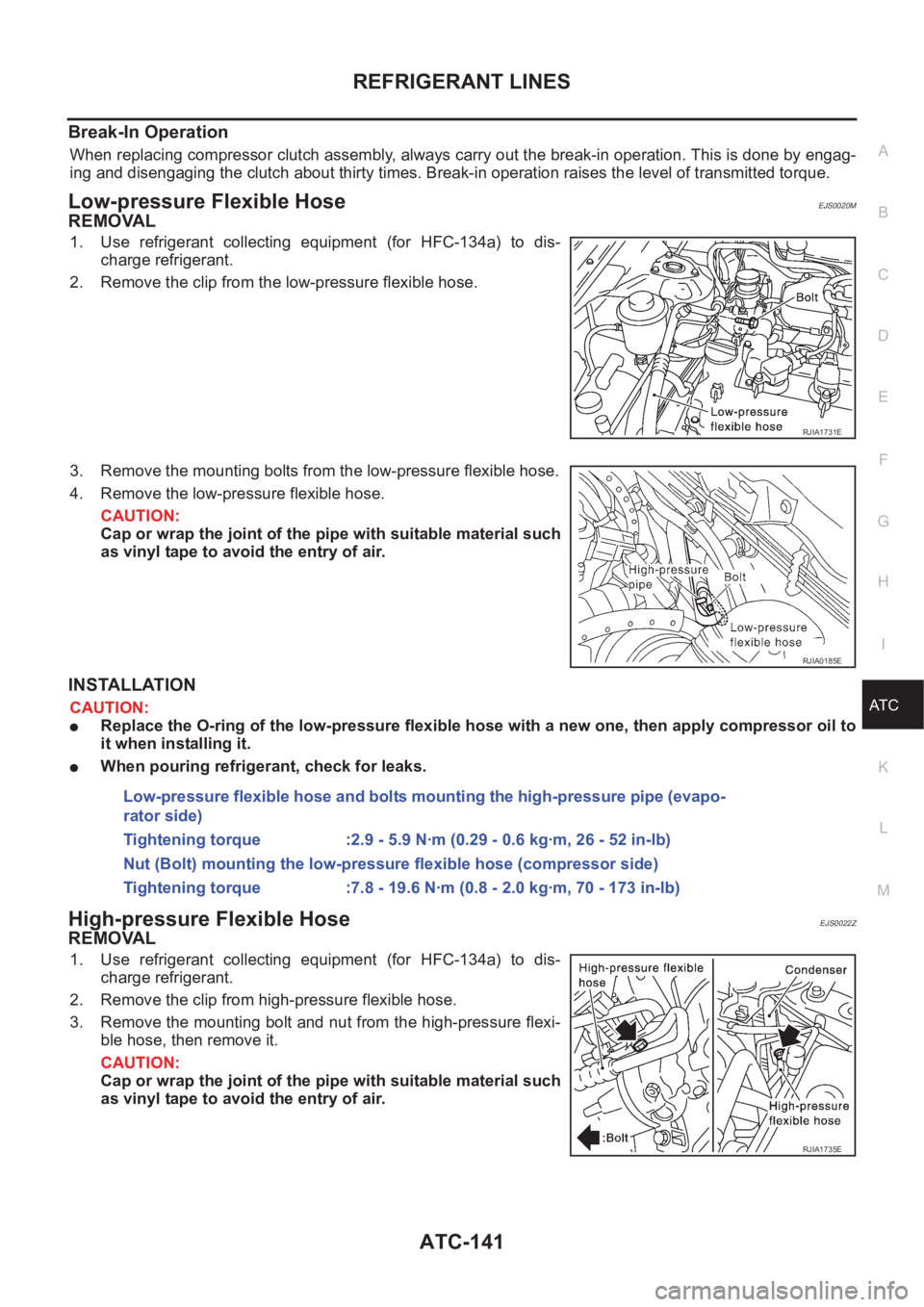
2. Remove the clip from the low-pressure flexible hose.
3. Remove the mounting bolts from the low-pressure flexible hose.
4. Remove the low-pressure flexible hose.
CAUTION:
Cap or wrap the joint of the pipe with suitable material such
as vinyl tape to avoid the entry of air.
INSTALLATION
CAUTION:
●Replace the O-ring of the low-pressure flexible hose with a new one, then apply compressor oil to
it when installing it.
●When pouring refrigerant, check for leaks.
High-pressure Flexible HoseEJS0022Z
REMOVAL
1. Use refrigerant collecting equipment (for HFC-134a) to dis-
charge refrigerant.
2. Remove the clip from high-pressure flexible hose.
3. Remove the mounting bolt and nut from the high-pressure flexi-
ble hose, then remove it.
CAUTION:
Cap or wrap the joint of the pipe with suitable material such
as vinyl tape to avoid the entry of air.
RJIA1731E
RJIA0185E
Low-pressure flexible hose and bolts mounting the high-pressure pipe (evapo-
rator side)
Tightening torque :2.9 - 5.9 N·m (0.29 - 0.6 kg·m, 26 - 52 in-lb)
Nut (Bolt) mounting the low-pressure flexible hose (compressor side)
Tightening torque :7.8 - 19.6 N·m (0.8 - 2.0 kg·m, 70 - 173 in-lb)
RJIA1735E
Page 2936 of 3189
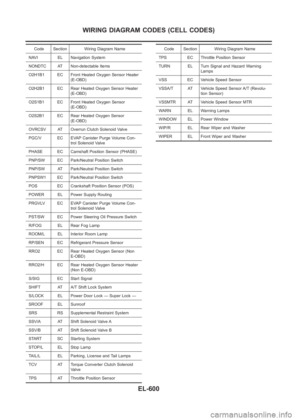
Code Section Wiring Diagram Name
NAVI EL Navigation System
NONDTC AT Non-detectable Items
O2H1B1 EC Front Heated Oxygen Sensor Heater
(E-OBD)
O2H2B1 EC Rear Heated Oxygen Sensor Heater
(E-OBD)
O2S1B1 EC Front Heated Oxygen Sensor
(E-OBD)
O2S2B1 EC Rear Heated Oxygen Sensor
(E-OBD)
OVRCSV AT Overrun Clutch Solenoid Valve
PGC/V EC EVAP Canister Purge Volume Con-
trol Solenoid Valve
PHASE EC Camshaft Position Sensor (PHASE)
PNP/SW EC Park/Neutral Position Switch
PNP/SW AT Park/Neutral Position Switch
PNPSW1 EC Park/Neutral Position Switch
POS EC Crankshaft Position Sensor (POS)
POWER EL Power Supply Routing
PRGVLV EC EVAP Canister Purge Volume Con-
trol Solenoid Valve
PST/SW EC Power Steering Oil Pressure Switch
R/FOG EL Rear Fog Lamp
ROOM/L EL Interior Room Lamp
RP/SEN EC Refrigerant Pressure Sensor
RRO2 EC Rear Heated Oxygen Sensor (Non
E-OBD)
RRO2/H EC Rear Heated Oxygen Sensor Heater
(Non E-OBD)
S/SIG EC Start Signal
SHIFT AT A/T Shift Lock System
S/LOCK EL Power Door Lock — Super Lock —
SROOF EL Sunroof
SRS RS Supplemental Restraint System
SSV/A AT Shift Solenoid Valve A
SSV/B AT Shift Solenoid Valve B
START SC Starting System
STOP/L EL Stop Lamp
TAIL/L EL Parking, License and Tail Lamps
TCV AT Torque Converter Clutch Solenoid
Valve
TPS AT Throttle Position SensorCode Section Wiring Diagram Name
TPS EC Throttle Position Sensor
TURN EL Turn Signal and Hazard Warning
Lamps
VSS EC Vehicle Speed Sensor
VSSA/T AT Vehicle Speed Sensor A/T (Revolu-
tion Sensor)
VSSMTR AT Vehicle Speed Sensor MTR
WARN EL Warning Lamps
WINDOW EL Power Window
WIP/R EL Rear Wiper and Washer
WIPER EL Front Wiper and Washer
WIRING DIAGRAM CODES (CELL CODES)
EL-600
Page 2937 of 3189
HEATER &
MANUAL AIR CONDITIONER
SECTION
HA
CONTENTS
MANUAL
PRECAUTIONS<0011001100110011001100110011001100110011001100110011001100110011001100110011001100110011001100110011001100110011001100110011001100110011001100110011001100110011001100110011001100110011001100110011001100
11001100110011001100110011001100110011001100110011[2
Supplemental Restraint System (SRS)″AIR
BAG″and″SEAT BELT PRE-TENSIONER″...............2
Precautions for Working with HFC-134a (R-134a) .....2
General Refrigerant Precautions .................................2
Precautions for Refrigerant Connection ......................3
Precautions for Servicing Compressor ........................5
Precautions for Service Equipment .............................6
Wiring Diagrams and Trouble Diagnosis .....................8
PREPARATION<0011001100110011001100110011001100110011001100110011001100110011001100110011001100110011001100110011001100110011001100110011001100110011001100110011001100110011001100110011001100110011001100110011001100
11001100110011001100110011001100110011001100110011[9
Special Service Tools ..................................................9
HFC-134a (R-134a) Service Tools and
Equipment <0011001100110011001100110011001100110011001100110011001100110011001100110011001100110011001100110011001100110011001100110011001100110011001100110011001100110011001100110011001100110011001100110011001100
11001100110011[............10
DESCRIPTION<0011001100110011001100110011001100110011001100110011001100110011001100110011001100110011001100110011001100110011001100110011001100110011001100110011001100110011001100110011001100110011001100110011001100
11001100110011001100110011001100110011001100110011[12
Refrigeration System .................................................12
CSV613 Variable Displacement Compressor............13
Component Layout ....................................................17
Control Operation ......................................................18
Discharge Air Flow.....................................................19
System Description ....................................................20
TROUBLE DIAGNOSES................................................21
Component Location..................................................21
Wiring Diagram - Heater............................................23
Circuit Diagram - Air Conditioner...............................24
Wiring Diagram - A/C, M - .........................................25
How to Perform Trouble Diagnoses for Quick
and Accurate Repair ..................................................34Operational Check .....................................................35
Intake Door <0011001100110011001100110011001100110011001100110011001100110011001100110011001100110011001100110011001100110011001100110011001100110011001100110011001100110011001100110011001100110011001100110011001100
1100110011[...........37
Mode Door <0011001100110011001100110011001100110011001100110011001100110011001100110011001100110011001100110011001100110011001100110011001100110011001100110011001100110011001100110011001100110011001100110011001100
110011001100110011[..........41
Air Mix Door <0011001100110011001100110011001100110011001100110011001100110011001100110011001100110011001100110011001100110011001100110011001100110011001100110011001100110011001100110011001100110011001100110011001100
1100110011[..........43
Blower Motor<0011001100110011001100110011001100110011001100110011001100110011001100110011001100110011001100110011001100110011001100110011001100110011001100110011001100110011001100110011001100110011001100110011001100
110011[..........45
Magnet Clutch<0011001100110011001100110011001100110011001100110011001100110011001100110011001100110011001100110011001100110011001100110011001100110011001100110011001100110011001100110011001100110011001100110011001100
11[.........52
Insufficient Cooling ....................................................66
Insufficient Heating ....................................................75
Noise <0011001100110011001100110011001100110011001100110011001100110011001100110011001100110011001100110011001100110011001100110011001100110011001100110011001100110011001100110011001100110011001100110011001100
110011001100110011001100110011[................76
SERVICE PROCEDURE................................................77
HFC-134a (R-134a) Service Procedure ....................77
Maintenance of Lubricant Quantity in
Compressor <0011001100110011001100110011001100110011001100110011001100110011001100110011001100110011001100110011001100110011001100110011001100110011001100110011001100110011001100110011001100110011001100110011001100
1100110011[..........79
Compressor <0011001100110011001100110011001100110011001100110011001100110011001100110011001100110011001100110011001100110011001100110011001100110011001100110011001100110011001100110011001100110011001100110011001100
1100110011[..........82
Compressor Clutch - CSV613 (CALSONIC
make) <0011001100110011001100110011001100110011001100110011001100110011001100110011001100110011001100110011001100110011001100110011001100110011001100110011001100110011001100110011001100110011001100110011001100
110011001100110011001100110011[...............83
Heater & Cooling Unit (Heater Core) ........................87
A/C Evaporator ..........................................................87
Blower Unit <0011001100110011001100110011001100110011001100110011001100110011001100110011001100110011001100110011001100110011001100110011001100110011001100110011001100110011001100110011001100110011001100110011001100
1100110011[...........89
Refrigerant Lines .......................................................90
Belt <0011001100110011001100110011001100110011001100110011001100110011001100110011001100110011001100110011001100110011001100110011001100110011001100110011001100110011001100110011001100110011001100110011001100
1100110011001100110011001100110011[..................94
Ventilation Air Filter ....................................................95
SERVICE DATA AND SPECIFICATIONS (SDS).........96
Compressor <0011001100110011001100110011001100110011001100110011001100110011001100110011001100110011001100110011001100110011001100110011001100110011001100110011001100110011001100110011001100110011001100110011001100
1100110011[..........96
Lubricant <0011001100110011001100110011001100110011001100110011001100110011001100110011001100110011001100110011001100110011001100110011001100110011001100110011001100110011001100110011001100110011001100110011001100
11001100110011[..............96
Refrigerant <0011001100110011001100110011001100110011001100110011001100110011001100110011001100110011001100110011001100110011001100110011001100110011001100110011001100110011001100110011001100110011001100110011001100
110011[.............96
Engine Idling Speed (When A/C is On).....................96
Belt Tension <0011001100110011001100110011001100110011001100110011001100110011001100110011001100110011001100110011001100110011001100110011001100110011001100110011001100110011001100110011001100110011001100110011001100
110011[...........96
GI
MA
EM
LC
EC
FE
CL
MT
AT
AX
SU
BR
ST
RS
BT
SC
EL
IDX
Page 2941 of 3189
When installing an air conditioner in the vehicle, connect the pipes as thefinal stage of the opera-
tion. Do not remove the seal caps of pipes and other components until just before required for
connection.
Allow components stored in cool areas to warm to working area temperature before removing seal
caps. This prevents condensation from forming inside A/C components.
Thoroughly remove moisture from the refrigeration system before charging the refrigerant.
Always replace used O-rings.
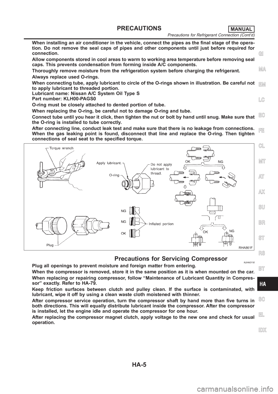
When connecting tube, apply lubricant to circle of the O-rings shown in illustration. Be careful not
to apply lubricant to threaded portion.
Lubricant name: Nissan A/C System Oil Type S
Part number: KLH00-PAGS0
O-ring must be closely attached to dented portion of tube.
When replacing the O-ring, be careful not to damage O-ring and tube.
Connect tube until you hear it click, then tighten the nut or bolt by hand until snug. Make sure that
the O-ring is installed to tube correctly.
After connecting line, conduct leak test and make sure that there is no leakage from connections.
When the gas leaking point is found, disconnect that line and replace the O-ring. Then tighten
connections of seal seat to the specified torque.
RHA861F
Precautions for Servicing CompressorNJHA0116Plug all openings to prevent moisture and foreign matter from entering.
When the compressor is removed, store it in the same position as it is when mounted on the car.
When replacing or repairing compressor, follow “Maintenance of Lubricant Quantity in Compres-
sor” exactly. Refer to HA-79.
Keep friction surfaces between clutch and pulley clean. If the surface is contaminated, with
lubricant, wipe it off by using a clean waste cloth moistened with thinner.
After compressor service operation, turn the compressor shaft by hand more than five turns in
both directions. This will equally distribute lubricant inside the compressor. After the compressor
is installed, let the engine idle and operate the compressor for one hour.
After replacing the compressor magnet clutch, apply voltage to the new oneand check for usual
operation.
GI
MA
EM
LC
EC
FE
CL
MT
AT
AX
SU
BR
ST
RS
BT
SC
EL
IDX
PRECAUTIONSMANUAL
Precautions for Refrigerant Connection (Cont’d)
HA-5
Page 2945 of 3189
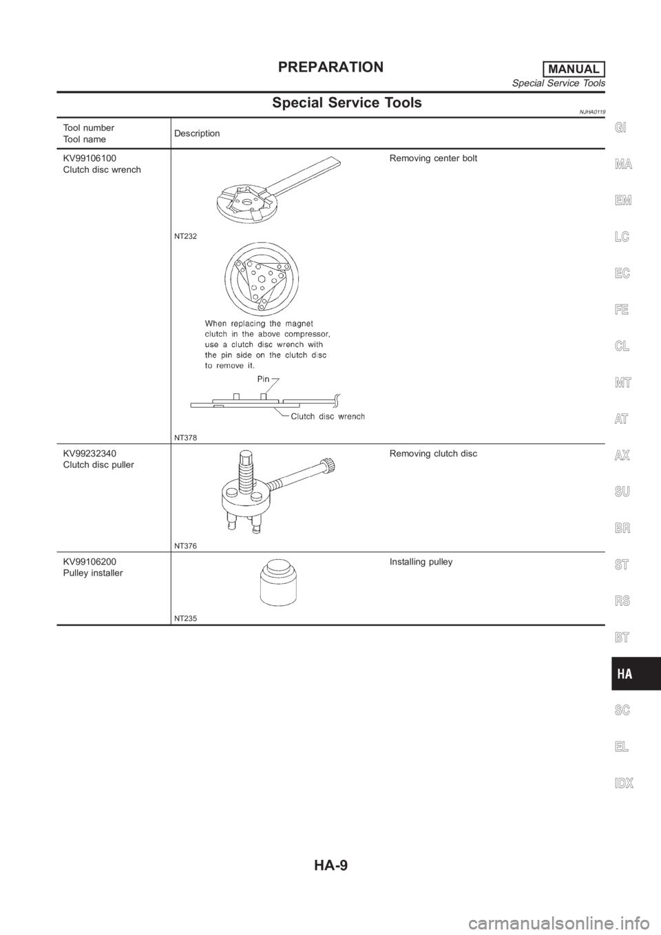
Special Service ToolsNJHA0119
Tool number
Tool nameDescription
KV99106100
Clutch disc wrench
NT232
NT378
Removing center bolt
KV99232340
Clutch disc puller
NT376
Removing clutch disc
KV99106200
Pulley installer
NT235
Installing pulley
GI
MA
EM
LC
EC
FE
CL
MT
AT
AX
SU
BR
ST
RS
BT
SC
EL
IDX
PREPARATIONMANUAL
Special Service Tools
HA-9
Page 2949 of 3189
CSV613 Variable Displacement Compressor
GENERAL INFORMATIONNJHA02061. The CSV613 compressor differs from previous units. The vent temperatures of the CSV613 compressor
do not drop too far below 5°C (41°F) when:
evaporator intake air temperature is less than 20°C (68°F)
engine is running at speeds less than 1,500 rpm.
This is because the CSV613 compressor provides a means of “capacity” control.
2. The CSV613 compressor provides refrigerant control under varying conditions. During cold winters, it may
not produce high refrigerant pressure discharge (compared to previous units) when used with air condi-
tioning systems.
3. A “clanking” sound may occasionally be heard during refrigerant charge. The sound indicates that the tilt
angle of the swash plate has changed and is not a problem.
4. For air conditioning systems with the CSV613 compressor, the clutch remains engaged unless: the sys-
tem main switch, fan switch or ignition switch is turned OFF. When ambient (outside) temperatures are
low or when the amount of refrigerant is insufficient, the clutch is disengaged to protect the compressor.
5. A constant range of suction pressure is maintained when engine speed is greater than a certain value. It
normally ranges from 147 to 177 kPa (1.47 to 1.77 bar, 1.5 to 1.8 kg/cm
2, 21 to 26 psi) under varying con-
ditions.
In previous compressors, however, suction pressure was reduced with increases in engine speed.
GI
MA
EM
LC
EC
FE
CL
MT
AT
AX
SU
BR
ST
RS
BT
SC
EL
IDX
DESCRIPTIONMANUAL
CSV613 Variable Displacement Compressor
HA-13
Page 2970 of 3189
How to Perform Trouble Diagnoses for Quick
and Accurate Repair
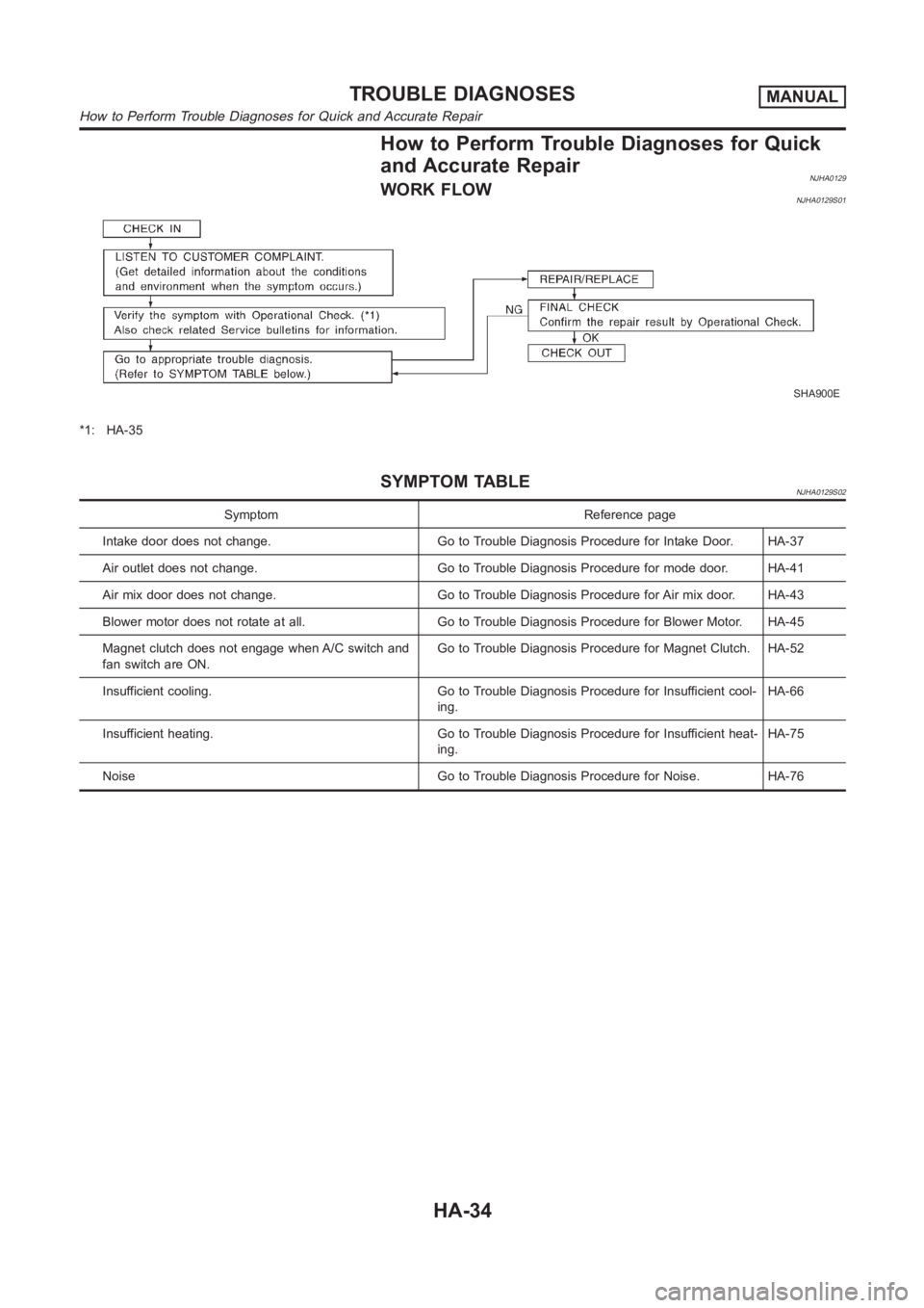
NJHA0129WORK FLOWNJHA0129S01
SHA900E
*1: HA-35
SYMPTOM TABLENJHA0129S02
Symptom Reference page
Intake door does not change. Go to Trouble Diagnosis Procedure for Intake Door. HA-37
Air outlet does not change. Go to Trouble Diagnosis Procedure for mode door. HA-41
Air mix door does not change. Go to Trouble Diagnosis Procedure for Air mix door. HA-43
Blower motor does not rotate at all. Go to Trouble Diagnosis Procedure for Blower Motor. HA-45
Magnet clutch does not engage when A/C switch and
fan switch are ON.Go to Trouble Diagnosis Procedure for Magnet Clutch. HA-52
Insufficient cooling. Go to Trouble Diagnosis Procedure for Insufficient cool-
ing.HA-66
Insufficient heating. Go to Trouble Diagnosis Procedure for Insufficientheat-
ing.HA-75
Noise Go to Trouble Diagnosis Procedure for Noise. HA-76
TROUBLE DIAGNOSESMANUAL
How to Perform Trouble Diagnoses for Quick and Accurate Repair
HA-34
Page 2972 of 3189
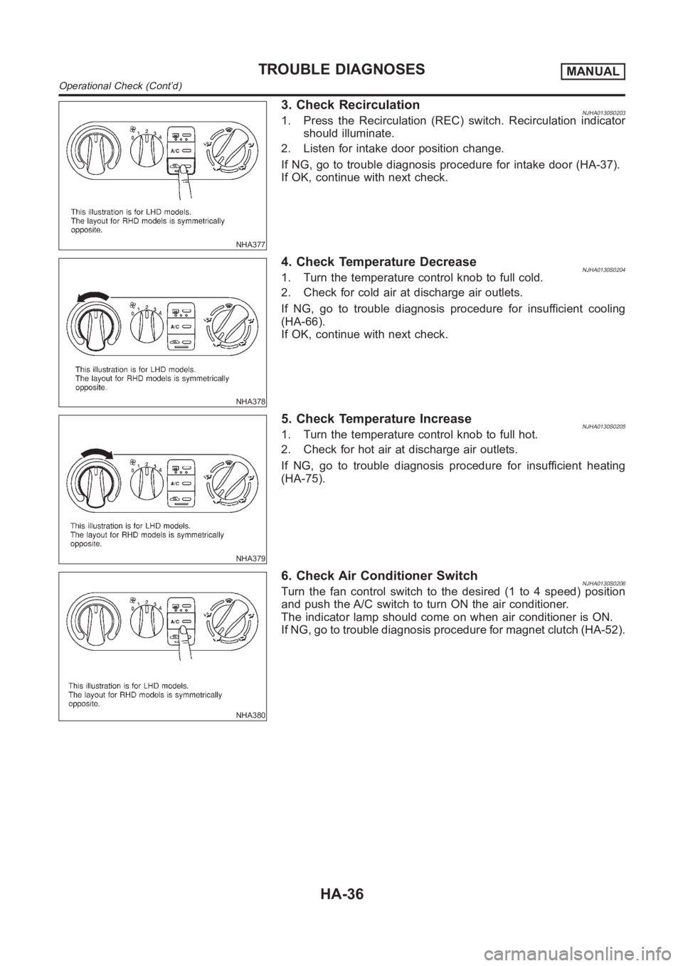
NHA377
3. Check RecirculationNJHA0130S02031. Press the Recirculation (REC) switch. Recirculation indicator
should illuminate.
2. Listen for intake door position change.
If NG, go to trouble diagnosis procedure for intake door (HA-37).
If OK, continue with next check.
NHA378
4. Check Temperature DecreaseNJHA0130S02041. Turn the temperature control knob to full cold.
2. Check for cold air at discharge air outlets.
If NG, go to trouble diagnosis procedure for insufficient cooling
(HA-66).
If OK, continue with next check.
NHA379
5. Check Temperature IncreaseNJHA0130S02051. Turn the temperature control knob to full hot.
2. Check for hot air at discharge air outlets.
If NG, go to trouble diagnosis procedure for insufficient heating
(HA-75).
NHA380
6. Check Air Conditioner SwitchNJHA0130S0206Turn the fan control switch to the desired (1 to 4 speed) position
and push the A/C switch to turn ON the air conditioner.
The indicator lamp should come on when air conditioner is ON.
If NG, go to trouble diagnosis procedure for magnet clutch (HA-52).
TROUBLE DIAGNOSESMANUAL
Operational Check (Cont’d)
HA-36