Page 2004 of 3189

ATC-24
AIR CONDITIONER CONTROL
FAN SPEED CONTROL
Blower speed is automatically controlled based on temperature setting, ambient temperature, in-vehicle tem-
perature, intake temperature, amount of sunload and air mix door position.
With FAN switch set to AUTO, the blower motor starts to gradually increase air flow volume.
When engine coolant temperature is low, the blower motor operation is delayed to prevent cool air from flow-
ing.
INTAKE DOOR CONTROL
The intake doors are automatically controlled by: The temperature setting, ambient temperature, in-vehicle
temperature, intake temperature, amount of sunload and ON-OFF operation of the compressor.
OUTLET DOOR CONTROL
The outlet door is automatically controlled by: The temperature setting, ambient temperature, in-vehicle tem-
perature, intake temperature and amount of sunload.
MAGNET CLUTCH CONTROL
The ECM controls compressor operation using input signals from the refrigerant pressure sensor (with QG
engine), throttle position sensor and auto amplifier.
SELF-DIAGNOSTIC SYSTEM
The self-diagnostic system is built into the auto amplifier (LCU) to quickly locate the cause of problems.
Overview of Control systemEJS001Z7
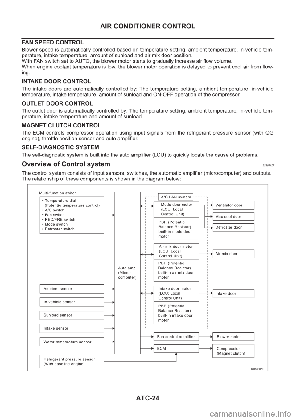
The control system consists of input sensors, switches, the automatic amplifier (microcomputer) and outputs.
The relationship of these components is shown in the diagram below:
RJIA0687E
Page 2009 of 3189

TROUBLE DIAGNOSIS
ATC-29
C
D
E
F
G
H
I
K
L
MA
B
AT C
TROUBLE DIAGNOSISPFP:00004
How to Perform Trouble Diagnoses for Quick and Accurate RepairEJS001ZC
WORK FLOW
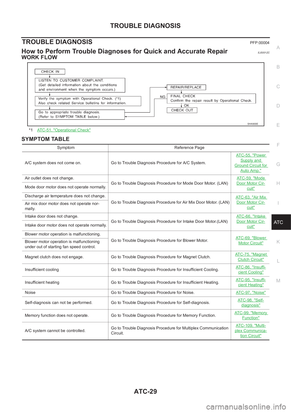
SYMPTOM TABLE
*1AT C - 5 1 , "Operational Check"
SHA900E
Symptom Reference Page
A/C system does not come on. Go to Trouble Diagnosis Procedure for A/C System.ATC-55, "
Power
Supply and
Ground Circuit for
Auto Amp."
Air outlet does not change.
Go to Trouble Diagnosis Procedure for Mode Door Motor. (LAN)AT C - 5 9 , "Mode
Door Motor Cir-
cuit"Mode door motor does not operate normally.
Discharge air temperature does not change.
Go to Trouble Diagnosis Procedure for Air Mix Door Motor. (LAN)ATC-63, "
Air Mix
Door Motor Cir-
cuit"Air mix door motor does not operate nor-
mally.
Intake door does not change.
Go to Trouble Diagnosis Procedure for Intake Door Motor.(LAN)AT C - 6 6 , "
Intake
Door Motor Cir-
cuit"Intake door motor does not operate normally.
Blower motor operation is malfunctioning.
Go to Trouble Diagnosis Procedure for Blower Motor.ATC-69, "
Blower
Motor Circuit"Blower motor operation is malfunctioning
under out of starting fan speed control.
Magnet clutch does not engage. Go to Trouble Diagnosis Procedure for Magnet Clutch.AT C - 7 5 , "
Magnet
Clutch Circuit"
Insufficient cooling Go to Trouble Diagnosis Procedure for Insufficient Cooling.AT C - 8 6 , "Insuffi-
cient Cooling"
Insufficient heating Go to Trouble Diagnosis Procedure for Insufficient Heating.AT C - 9 5 , "Insuffi-
cient Heating"
Noise Go to Trouble Diagnosis Procedure for Noise.ATC-97, "Noise"
Self-diagnosis can not be performed. Go to Trouble Diagnosis Procedure for Self-diagnosis.AT C - 9 8 , "Self-
diagnosis"
Memory function does not operate. Go to Trouble Diagnosis Procedure for Memory Function.AT C - 9 9 , "Memory
Function"
A/C system cannot be controlled.Go to Trouble Diagnosis Procedure for Multiplex Communication
Circuit.ATC-109, "
Multi-
plex Communica-
tion Circuit"
Page 2026 of 3189

ATC-46
TROUBLE DIAGNOSIS
8. CHECK ACTUATORS
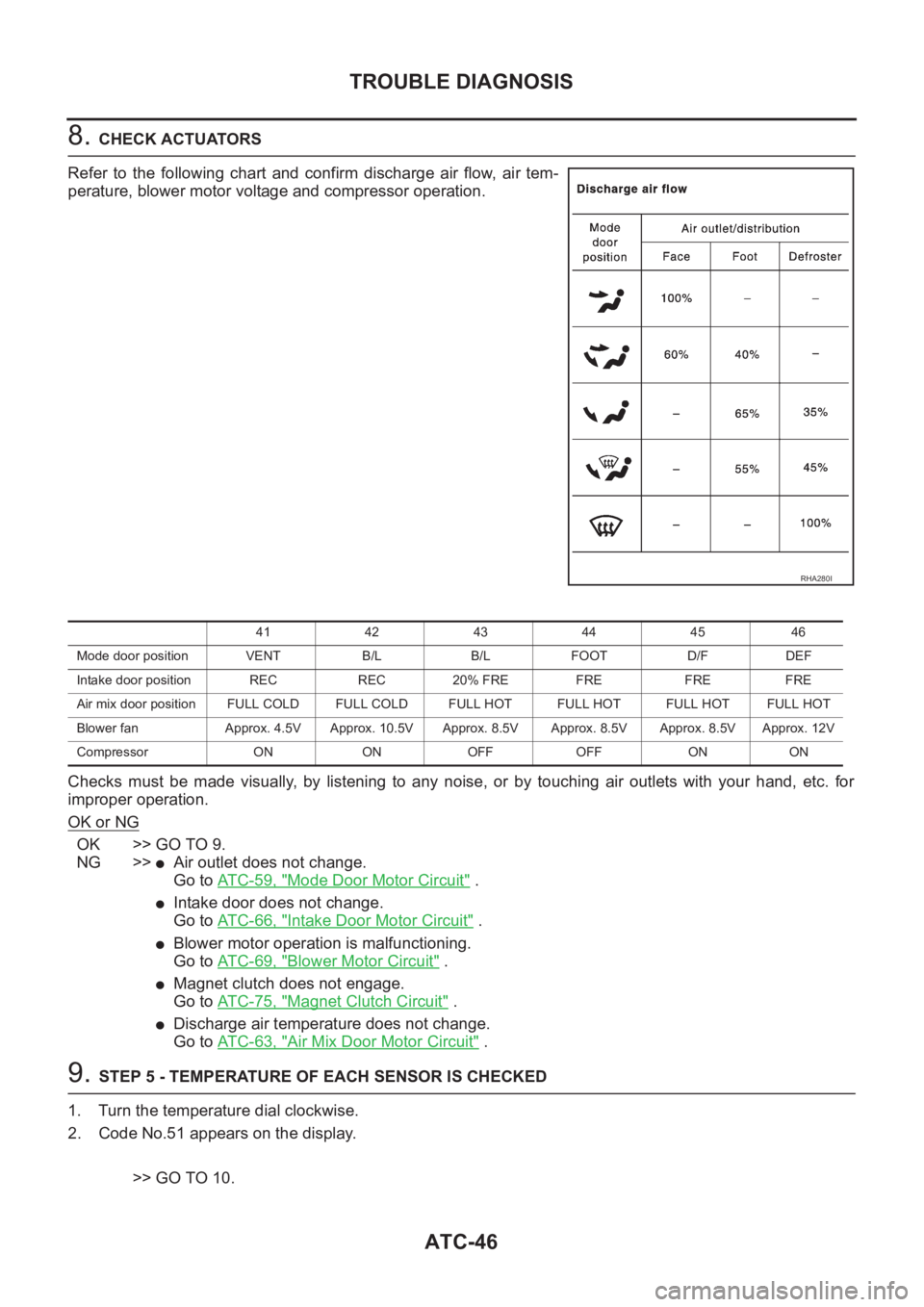
Refer to the following chart and confirm discharge air flow, air tem-
perature, blower motor voltage and compressor operation.
Checks must be made visually, by listening to any noise, or by touching air outlets with your hand, etc. for
improper operation.
OK or NG
OK >> GO TO 9.
NG >>
●Air outlet does not change.
Go to AT C - 5 9 , "
Mode Door Motor Circuit" .
●Intake door does not change.
Go to AT C - 6 6 , "
Intake Door Motor Circuit" .
●Blower motor operation is malfunctioning.
Go to AT C - 6 9 , "
Blower Motor Circuit" .
●Magnet clutch does not engage.
Go to AT C - 7 5 , "
Magnet Clutch Circuit" .
●Discharge air temperature does not change.
Go to AT C - 6 3 , "
Air Mix Door Motor Circuit" .
9. STEP 5 - TEMPERATURE OF EACH SENSOR IS CHECKED
1. Turn the temperature dial clockwise.
2. Code No.51 appears on the display.
>> GO TO 10.
RHA280I
41 42 43 44 45 46
Mode door position VENT B/L B/L FOOT D/F DEF
Intake door position REC REC 20% FRE FRE FRE FRE
Air mix door position FULL COLD FULL COLD FULL HOT FULL HOT FULL HOTFULL HOT
Blower fan Approx. 4.5V Approx. 10.5V Approx. 8.5V Approx. 8.5V Approx. 8.5V Approx. 12V
Compressor ON ON OFF OFF ON ON
Page 2032 of 3189
ATC-52
TROUBLE DIAGNOSIS
CHECKING DISCHARGE AIR
1. Press mode switch four times and DEF button.
2. Each position indicator should change shape.
3. Confirm that discharge air comes out according to the air distri-
bution table. Refer to ATC-27, "
Discharge Air Flow" .
Intake door position is checked in the next step.
If NG, go to AT C - 5 9 , "
Mode Door Motor Circuit" .
If OK, continue with next check.
NOTE:
Confirm that the compressor clutch is engaged (visual inspection)
and intake door position is at FRESH when the DEF is selected.
RJIA1685E
RHA280I
Page 2034 of 3189
ATC-54
TROUBLE DIAGNOSIS
CHECKING AUTO MODE
1. Press temperature dial.
2. Display should indicate AUTO (not ECON).
●Confirm that the compressor clutch engages (audio or visual
inspection). (Discharge air and blower speed will depend on
ambient, in-vehicle, and set temperatures.)
If NG, go to AT C - 5 5 , "
Power Supply and Ground Circuit for Auto
Amp." , then if necessary, go to AT C - 7 5 , "Magnet Clutch Circuit" .
If all operational check are OK (symptom can not be duplicated), go
to Incident Simulation Tests in GI-22, "How to Perform Efficient Diag-
nosis for an Electrical Incident" and perform tests as outlined to sim-
ulate driving conditions environment. If symptom appears, refer to
AT C - 2 9 , "
SYMPTOM TABLE" and perform applicable trouble diag-
nosis procedures.
RJIA1690E
Page 2055 of 3189
TROUBLE DIAGNOSIS
ATC-75
C
D
E
F
G
H
I
K
L
MA
B
AT C
Magnet Clutch CircuitEJS001ZP
SYMPTOM: Magnet clutch does not engage.
INSPECTION FLOW
*1ATC-42, "Self-diagnosis Function",
see No.1.*2ATC-100, "Ambient Sensor Circuit"*3ATC-102, "In-vehicle Sensor Circuit"
*4ATC-105, "Sunload Sensor Circuit"*5AT C - 6 3 , "Air Mix Door Motor Circuit"*6ATC-42, "Self-diagnosis Function",
see No. 14.
*7ATC-75, "
Magnet Clutch Circuit"*8AT C - 9 2 , "TROUBLE DIAGNOSES
FOR UNUSUAL PRESSURE"
*9ATC-51, "Operational Check"
*10ATC-42, "Self-diagnosis Function"
see No.5 or 7.*11AT C - 2 9 , "
SYMPTOM TABLE"*12ATC-108, "Intake Sensor Circuit"
RJIA1697E
Page 2056 of 3189
ATC-76
TROUBLE DIAGNOSIS
SYSTEM DESCRIPTION
Auto amplifier controls compressor operation by ambient temperature and signal from ECM.
Low Temperature Protection Control
Auto amplifier will turn the compressor ON or OFF as determined by
a signal detected by ambient sensor.
When ambient temperatures are greater than −2°C (28°F), the com-
pressor turns ON. The compressor turns OFF when ambient temper-
atures are less than −5°C (23°F).
DIAGNOSTIC PROCEDURE FOR MAGNET CLUTCH (WITH CAN SYSTEM)
SYMPTOM: Magnet clutch does not engage when A/C switch is ON.
RHA094GB
RJIA1698E
Page 2057 of 3189

TROUBLE DIAGNOSIS
ATC-77
C
D
E
F
G
H
I
K
L
MA
B
AT C
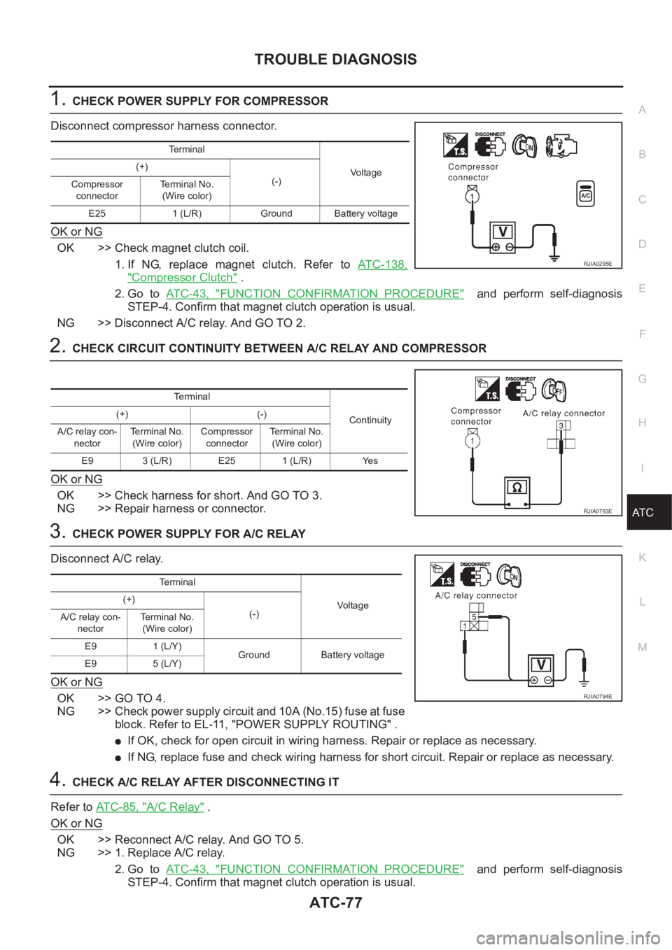
1.CHECK POWER SUPPLY FOR COMPRESSOR
Disconnect compressor harness connector.
OK or NG
OK >> Check magnet clutch coil.
1. If NG, replace magnet clutch. Refer to ATC-138,
"Compressor Clutch" .
2. Go to AT C - 4 3 , "
FUNCTION CONFIRMATION PROCEDURE" and perform self-diagnosis
STEP-4. Confirm that magnet clutch operation is usual.
NG >> Disconnect A/C relay. And GO TO 2.
2.CHECK CIRCUIT CONTINUITY BETWEEN A/C RELAY AND COMPRESSOR
OK or NG
OK >> Check harness for short. And GO TO 3.
NG >> Repair harness or connector.
3.CHECK POWER SUPPLY FOR A/C RELAY
Disconnect A/C relay.
OK or NG
OK >> GO TO 4.
NG >> Check power supply circuit and 10A (No.15) fuse at fuse
block. Refer to EL-11, "POWER SUPPLY ROUTING" .
●If OK, check for open circuit in wiring harness. Repair or replace as necessary.
●If NG, replace fuse and check wiring harness for short circuit. Repair or replace as necessary.
4.CHECK A/C RELAY AFTER DISCONNECTING IT
Refer to ATC-85, "
A/C Relay" .
OK or NG
OK >> Reconnect A/C relay. And GO TO 5.
NG >> 1. Replace A/C relay.
2. Go to AT C - 4 3 , "
FUNCTION CONFIRMATION PROCEDURE" and perform self-diagnosis
STEP-4. Confirm that magnet clutch operation is usual.
Terminal
Vo lta g e (+)
(-)
Compressor
connectorTe r m i n a l N o .
(Wire color)
E25 1 (L/R) Ground Battery voltage
RJIA0295E
Terminal
Continuity (+) (-)
A/C relay con-
nectorTerminal No.
(Wire color)Compressor
connectorTerminal No.
(Wire color)
E9 3 (L/R) E25 1 (L/R) Yes
RJIA0793E
Terminal
Vo l ta g e (+)
(-)
A/C relay con-
nectorTerminal No.
(Wire color)
E9 1 (L/Y)
Ground Battery voltage
E9 5 (L/Y)
RJIA0794E