Page 295 of 3189
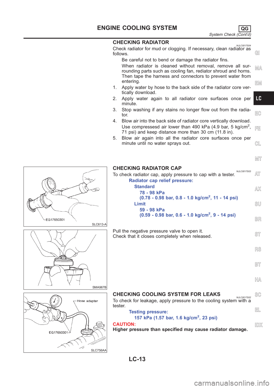
CHECKING RADIATORNJLC0017S04Check radiator for mud or clogging. If necessary, clean radiator as
follows.
Be careful not to bend or damage the radiator fins.
When radiator is cleaned without removal, remove all sur-
rounding parts such as cooling fan, rediator shroud and horns.
Then tape the harness and connectors to prevent water from
entering.
1. Apply water by hose to the back side of the radiator core ver-
tically download.
2. Apply water again to all radiator core surfaces once per
minute.
3. Stop washing if any stains no longer flow out from the radia-
tor.
4. Blow air into the back side of radiator core vertically download.
Use compressesd air lower than 490 kPa (4.9 bar, 5 kg/cm
2,
71 psi) and keep distance more than 30 cm (11.8 in).
5. Blow air again into all the radiator core surfaces once per
minute until no water sprays out.
SLC613-A
CHECKING RADIATOR CAPNJLC0017S03To check radiator cap, apply pressure to cap with a tester.
Radiator cap relief pressure:
Standard
78 - 98 kPa
(0.78 - 0.98 bar, 0.8 - 1.0 kg/cm
2, 11 - 14 psi)
Limit
59 - 98 kPa
(0.59 - 0.98 bar, 0.6 - 1.0 kg/cm
2,9-14psi)
SMA967B
Pull the negative pressure valve to open it.
Check that it closes completely when released.
SLC756AA
CHECKING COOLING SYSTEM FOR LEAKSNJLC0017S02To check for leakage, apply pressure to the cooling system with a
tester.
Testing pressure:
157 kPa (1.57 bar, 1.6 kg/cm2,23psi)
CAUTION:
Higher pressure than specified may cause radiator damage.
GI
MA
EM
EC
FE
CL
MT
AT
AX
SU
BR
ST
RS
BT
HA
SC
EL
IDX
ENGINE COOLING SYSTEMQG
System Check (Cont’d)
LC-13
Page 296 of 3189
Water Pump
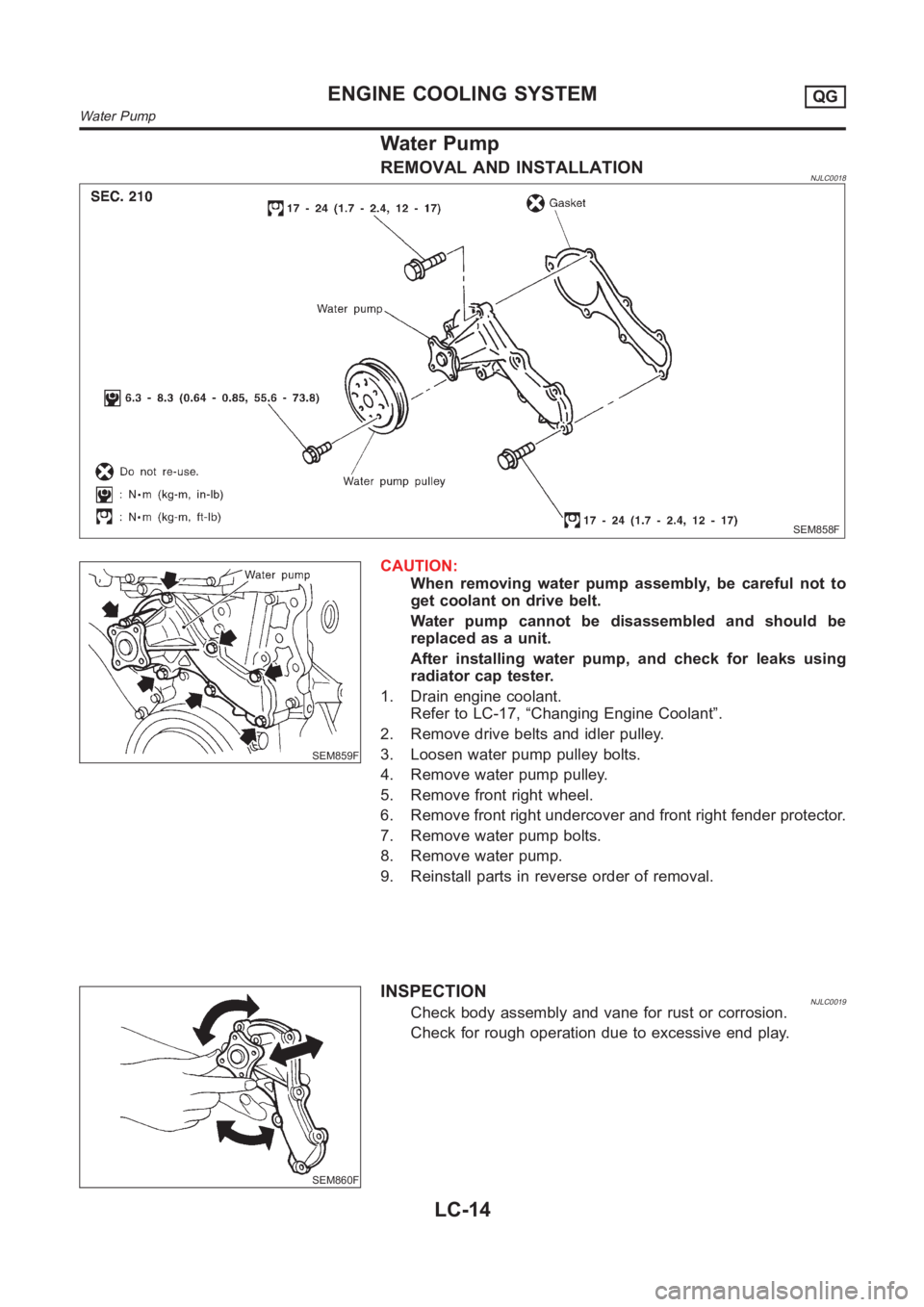
REMOVAL AND INSTALLATIONNJLC0018
SEM858F
SEM859F
CAUTION:
When removing water pump assembly, be careful not to
get coolant on drive belt.
Water pump cannot be disassembled and should be
replaced as a unit.
After installing water pump, and check for leaks using
radiator cap tester.
1. Drain engine coolant.
Refer to LC-17, “Changing Engine Coolant”.
2. Remove drive belts and idler pulley.
3. Loosen water pump pulley bolts.
4. Remove water pump pulley.
5. Remove front right wheel.
6. Remove front right undercover and front right fender protector.
7. Remove water pump bolts.
8. Remove water pump.
9. Reinstall parts in reverse order of removal.
SEM860F
INSPECTIONNJLC0019Check body assembly and vane for rust or corrosion.
Check for rough operation due to excessive end play.
ENGINE COOLING SYSTEMQG
Water Pump
LC-14
Page 297 of 3189
Thermostat
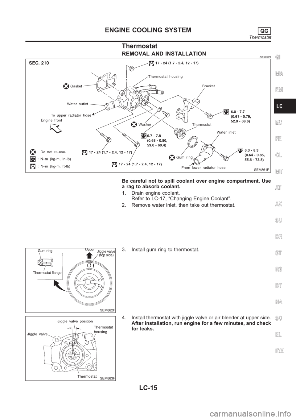
REMOVAL AND INSTALLATIONNJLC0021
SEM861F
Be careful not to spill coolant over engine compartment. Use
a rag to absorb coolant.
1. Drain engine coolant.
Refer to LC-17, “Changing Engine Coolant”.
2. Remove water inlet, then take out thermostat.
SEM862F
3. Install gum ring to thermostat.
SEM863F
4. Install thermostat with jiggle valve or air bleeder at upper side.
After installation, run engine for a few minutes, and check
for leaks.
GI
MA
EM
EC
FE
CL
MT
AT
AX
SU
BR
ST
RS
BT
HA
SC
EL
IDX
ENGINE COOLING SYSTEMQG
Thermostat
LC-15
Page 298 of 3189
SLC343
INSPECTIONNJLC00221. Check for valve seating condition at normal room temperature.
It should seat tightly.
2. Check valve opening temperature and valve lift.
Valve opening temperature °C (°F) 82 (180)
Valve lift mm/°C (in/°F) More than 8/95 (0.31/203)
3. Then check if valve closes at 5°C (9°F) below valve opening
temperature.
Radiator
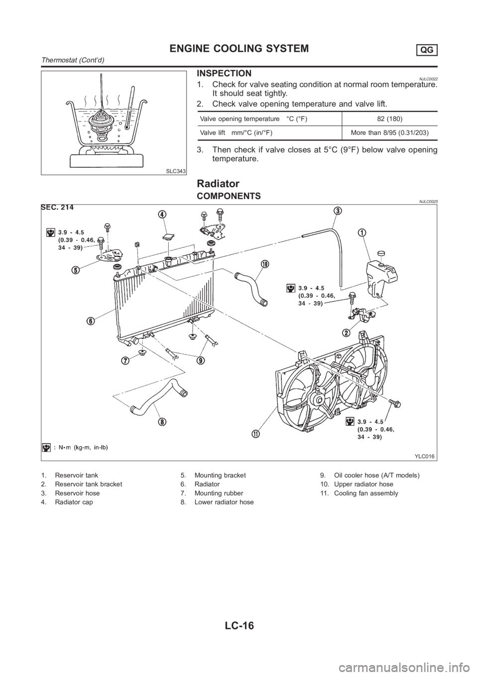
COMPONENTSNJLC0025
YLC016
1. Reservoir tank
2. Reservoir tank bracket
3. Reservoir hose
4. Radiator cap5. Mounting bracket
6. Radiator
7. Mounting rubber
8. Lower radiator hose9. Oil cooler hose (A/T models)
10. Upper radiator hose
11. Cooling fan assembly
ENGINE COOLING SYSTEMQG
Thermostat (Cont’d)
LC-16
Page 299 of 3189
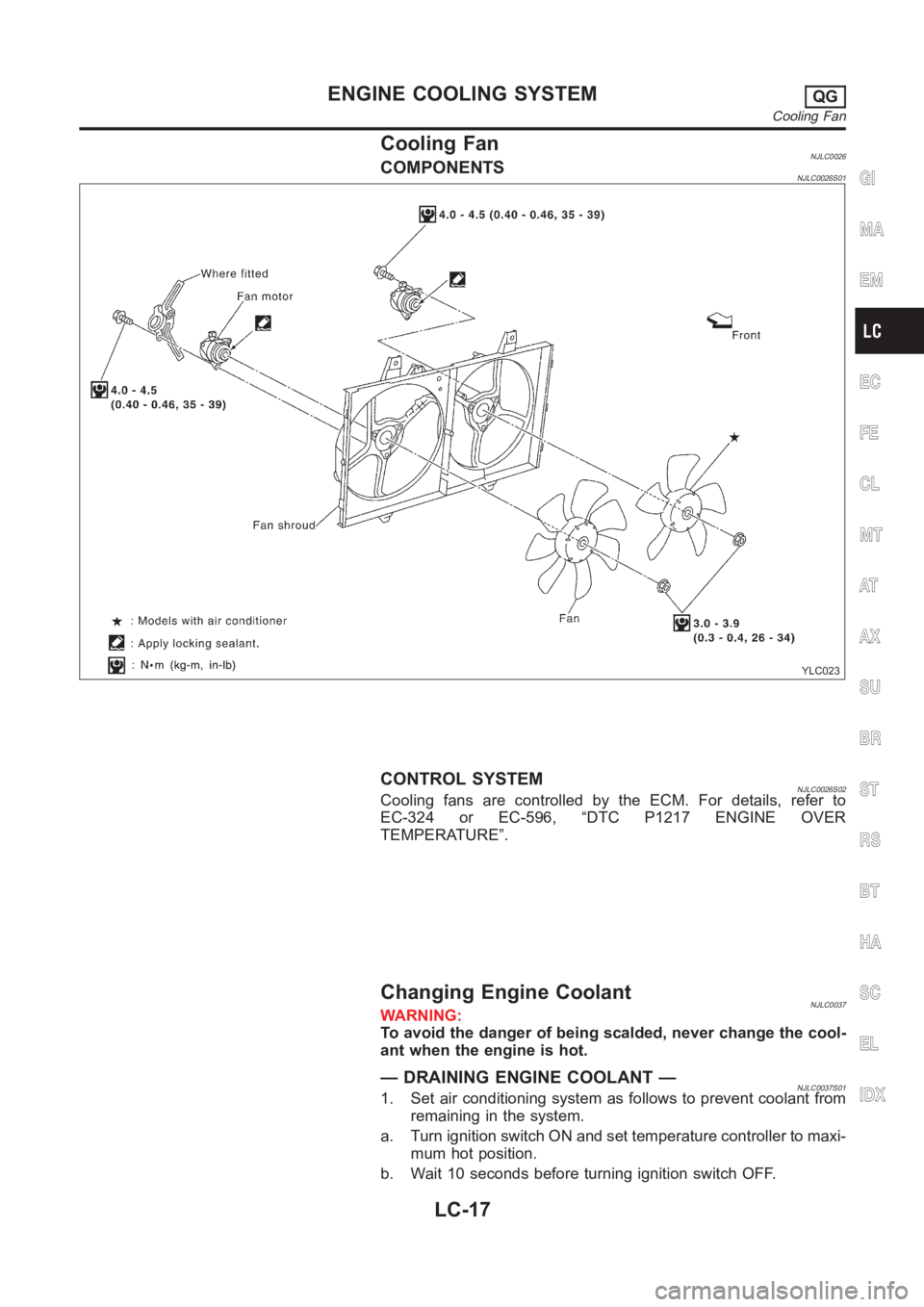
Cooling FanNJLC0026COMPONENTSNJLC0026S01
YLC023
CONTROL SYSTEMNJLC0026S02Cooling fans are controlled by the ECM. For details, refer to
EC-324 or EC-596, “DTC P1217 ENGINE OVER
TEMPERATURE”.
Changing Engine CoolantNJLC0037WARNING:
To avoid the danger of being scalded, never change the cool-
ant when the engine is hot.
— DRAINING ENGINE COOLANT —NJLC0037S011. Set air conditioning system as follows to prevent coolant from
remaining in the system.
a. Turn ignition switch ON and set temperature controller to maxi-
mum hot position.
b. Wait 10 seconds before turning ignition switch OFF.
GI
MA
EM
EC
FE
CL
MT
AT
AX
SU
BR
ST
RS
BT
HA
SC
EL
IDX
ENGINE COOLING SYSTEMQG
Cooling Fan
LC-17
Page 300 of 3189
SMA033D
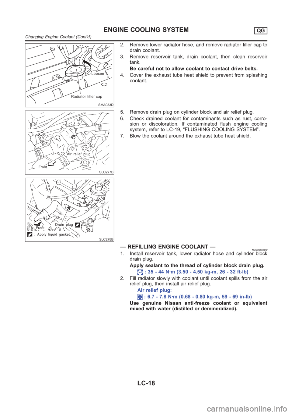
2. Remove lower radiator hose, and remove radiator filler cap to
drain coolant.
3. Remove reservoir tank, drain coolant, then clean reservoir
tank.
Be careful not to allow coolant to contact drive belts.
4. Cover the exhaust tube heat shield to prevent from splashing
coolant.
SLC277B
SLC278B
5. Remove drain plug on cylinder block and air relief plug.
6. Check drained coolant for contaminants such as rust, corro-
sion or discoloration. If contaminated flush engine cooling
system, refer to LC-19, “FLUSHING COOLING SYSTEM”.
7. Blow the coolant around the exhaust tube heat shield.
— REFILLING ENGINE COOLANT —NJLC0037S021. Install reservoir tank, lower radiator hose and cylinder block
drain plug.
Apply sealant to the thread of cylinder block drain plug.
: 35 - 44 N·m (3.50 - 4.50 kg-m, 26 - 32 ft-lb)
2. Fill radiator slowly with coolant until coolant spills from the air
relief plug, then install air relief plug.
Air relief plug:
: 6.7 - 7.8 N·m (0.68 - 0.80 kg-m, 59 - 69 in-lb)
Use genuine Nissan anti-freeze coolant or equivalent
mixed with water (distilled or demineralized).
ENGINE COOLING SYSTEMQG
Changing Engine Coolant (Cont’d)
LC-18
Page 301 of 3189
SMA182B
SMA412B
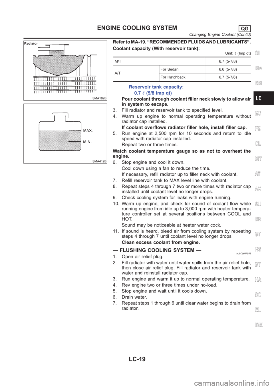
Refer to MA-19, “RECOMMENDED FLUIDS AND LUBRICANTS”.
Coolant capacity (With reservoir tank):
Unit:�(Imp qt)
M/T 6.7 (5-7/8)
A/TFor Sedan 6.6 (5-7/8)
For Hatchback 6.7 (5-7/8)
Reservoir tank capacity:
0.7�(5/8 Imp qt)
Pour coolant through coolant filler neck slowly to allow air
in system to escape.
3. Fill radiator and reservoir tank to specified level.
4. Warm up engine to normal operating temperature without
radiator cap installed.
If coolant overflows radiator filler hole, install filler cap.
5. Run engine at 2,500 rpm for 10 seconds and return to idle
speed with radiator cap installed.
Repeat two or three times.
Watch coolant temperature gauge so as not to overheat the
engine.
6. Stop engine and cool it down.
Cool down using a fan to reduce the time.
If necessary, refill radiator up to filler neck with coolant.
7. Refill reservoir tank to MAX level line with coolant.
8. Repeat steps 4 through 7 two or more times with radiator cap
installed until coolant level no longer drops.
9. Check cooling system for leaks with engine running.
10. Warm up engine, and check for sound of coolant flow while
running engine from idle up to 3,000 rpm with heater tempera-
ture controller set at several positions between COOL and
HOT.
Sound may be noticeable at heater water cock.
11. If sound is heard, bleed air from cooling system by repeating
steps 4 through 7 until coolant level no longer drops
Clean excess coolant from engine.
— FLUSHING COOLING SYSTEM —NJLC0037S031. Open air relief plug.
2. Fill radiator with water until water spills from the air relief hole,
then close air relief plug. Fill radiator and reservoir tank with
water and reinstall radiator cap.
3. Run engine and warm it up to normal operating temperature.
4. Rev engine two or three times under no-load.
5. Stop engine and wait until it cools down.
6. Drain water.
7. Repeat steps 1 through 6 until clear water begins to drain from
radiator.
GI
MA
EM
EC
FE
CL
MT
AT
AX
SU
BR
ST
RS
BT
HA
SC
EL
IDX
ENGINE COOLING SYSTEMQG
Changing Engine Coolant (Cont’d)
LC-19
Page 302 of 3189
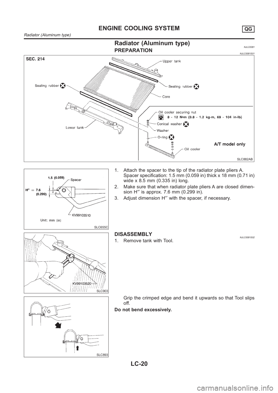
Radiator (Aluminum type)NJLC0081PREPARATIONNJLC0081S01
SLC882AB
SLC655C
1. Attach the spacer to the tip of the radiator plate pliers A.
Spacer specification: 1.5 mm (0.059 in) thick x 18 mm (0.71 in)
wide x 8.5 mm (0.335 in) long.
2. Make sure that when radiator plate pliers A are closed dimen-
sion H′′is approx. 7.6 mm (0.299 in).
3. Adjust dimension H′′with the spacer, if necessary.
SLC903
DISASSEMBLYNJLC0081S021. Remove tank with Tool.
SLC893
Grip the crimped edge and bend it upwards so that Tool slips
off.
Do not bend excessively.
ENGINE COOLING SYSTEMQG
Radiator (Aluminum type)
LC-20