2003 NISSAN ALMERA N16 Thermo
[x] Cancel search: ThermoPage 927 of 3189
![NISSAN ALMERA N16 2003 Electronic Repair Manual DTC P1217 ENGINE OVER TEMPERATURE
EC-597
[QG (WITHOUT EURO-OBD)]
C
D
E
F
G
H
I
J
K
L
MA
EC
On Board Diagnosis LogicEBS00KJ3
If the cooling fan or another component in the cooling system mal](/manual-img/5/57350/w960_57350-926.png "NISSAN ALMERA N16 2003 Electronic Repair Manual DTC P1217 ENGINE OVER TEMPERATURE
EC-597
[QG (WITHOUT EURO-OBD)]
C
D
E
F
G
H
I
J
K
L
MA
EC
On Board Diagnosis LogicEBS00KJ3
If the cooling fan or another component in the cooling system mal")
DTC P1217 ENGINE OVER TEMPERATURE
EC-597
[QG (WITHOUT EURO-OBD)]
C
D
E
F
G
H
I
J
K
L
MA
EC
On Board Diagnosis LogicEBS00KJ3
If the cooling fan or another component in the cooling system malfunctions, engine coolant temperature will
rise. When the engine coolant temperature reaches an abnormally high temperature condition, a malfunction
is indicated.
This self-diagnosis has the one trip detection logic.
CAUTION:
When a malfunction is indicated, be sure to replace the coolant. Refer to LC-11. Also, replace the
engine oil. Refer to LC-8.
1. Fill radiator with coolant up to specified level with a filling speed of 2 liters per minute. Be sure to
use coolant with the proper mixture ratio. Refer to MA-21.
2. After refilling coolant, run engine to ensure that no water-flow noise is emitted.
Overall Function CheckEBS00KJ4
Use this procedure to check the overall function of the cooling fan. During this check, a DTC might not be con-
firmed.
WARNING:
Never remove the radiator cap when the engine is hot. Serious burns could be caused by high pres-
sure fluid escaping from the radiator.
Wrap a thick cloth around cap. Carefully remove the cap by turning it a quarter turn to allow built-up
pressure to escape. Then turn the cap all the way off.
WITH CONSULT-II
1. Check the coolant level in the reservoir tank and radiator.
Allow engine to cool before checking coolant level.
If the coolant level in the reservoir tank and/or radiator is below
the proper range, skip the following steps and go to EC-600,
"Diagnostic Procedure" .
2. Confirm whether customer filled the coolant or not. If customer
filled the coolant, skip the following steps and go to EC-600,
"Diagnostic Procedure" .
3. Turn ignition switch “ON”.
DTC No. Trouble diagnosis name DTC detecting condition Possible cause
P1217
1217Engine over temperature
(Overheat)
●Cooling fan does not operate properly
(Overheat).
●Cooling fan system does not operate properly
(Overheat).
●Engine coolant was not added to the system
using the proper filling method.
●Harness or connectors
(The cooling fan circuit is open or
shorted.)
●Harness or connectors
(The CAN communication line is
open or shorted.)
●Cooling fan
●Radiator hose
●Radiator
●Radiator cap
●Water pump
●Thermostat
For more information, refer to EC-605,
"Main 12 Causes of Overheating" .
SEF621W
Page 931 of 3189
![NISSAN ALMERA N16 2003 Electronic Repair Manual DTC P1217 ENGINE OVER TEMPERATURE
EC-601
[QG (WITHOUT EURO-OBD)]
C
D
E
F
G
H
I
J
K
L
MA
EC
4.CHECK COOLING SYSTEM FOR LEAK
Apply pressure to the cooling system with a tester, and check if](/manual-img/5/57350/w960_57350-930.png "NISSAN ALMERA N16 2003 Electronic Repair Manual DTC P1217 ENGINE OVER TEMPERATURE
EC-601
[QG (WITHOUT EURO-OBD)]
C
D
E
F
G
H
I
J
K
L
MA
EC
4.CHECK COOLING SYSTEM FOR LEAK
Apply pressure to the cooling system with a tester, and check if")
DTC P1217 ENGINE OVER TEMPERATURE
EC-601
[QG (WITHOUT EURO-OBD)]
C
D
E
F
G
H
I
J
K
L
MA
EC
4.CHECK COOLING SYSTEM FOR LEAK
Apply pressure to the cooling system with a tester, and check if the
pressure drops.
CAUTION:
Higher than the specified pressure may cause radiator damage.
Pressure should not drop.
OK or NG
OK >> GO TO 5.
NG >> Check the following for leak
●Hose
●Radiator
●Water pump
Refer to LC-14.
5.CHECK RADIATOR CAP
Apply pressure to cap with a tester.
OK or NG
OK >> GO TO 6.
NG >> Replace radiator cap.
6.CHECK THERMOSTAT
1. Check valve seating condition at normal room temperatures.
It should seat tightly.
2. Check valve opening temperature and valve lift.
3. Check if valve is closed at 5°C (9°F) below valve opening tem-
perature.
For details, refer to LC-15.
OK or NG
OK >> GO TO 7.
NG >> Replace thermostat
7.CHECK ENGINE COOLANT TEMPERATURE SENSOR
Refer to EC-505, "
Component Inspection" .
OK or NG
OK >> GO TO 8.
NG >> Replace engine coolant temperature sensor.Testing pressure: 157 kPa (1.57 bar 1.6 kg/cm
2 , 23
psi)
SLC754A
Radiator cap relief pressure: 59 - 98 kPa
(0.59 - 0.98 bar 0.6 - 1.0 kg/
cm
2 , 9 - 14 psi)
SLC755A
Valve opening temperature: 82°C (180°F) [standard]
Valve lift: More than 8 mm/95°C
(0.31 in/203°F)
SLC343
Page 935 of 3189
![NISSAN ALMERA N16 2003 Electronic Repair Manual DTC P1217 ENGINE OVER TEMPERATURE
EC-605
[QG (WITHOUT EURO-OBD)]
C
D
E
F
G
H
I
J
K
L
MA
EC
7.CHECK COOLING FAN MOTORS
Refer to EC-606, "
Component Inspection" .
OK or NG
OK >> GO TO 8.
NG >> R](/manual-img/5/57350/w960_57350-934.png "NISSAN ALMERA N16 2003 Electronic Repair Manual DTC P1217 ENGINE OVER TEMPERATURE
EC-605
[QG (WITHOUT EURO-OBD)]
C
D
E
F
G
H
I
J
K
L
MA
EC
7.CHECK COOLING FAN MOTORS
Refer to EC-606, \"
Component Inspection\" .
OK or NG
OK >> GO TO 8.
NG >> R")
DTC P1217 ENGINE OVER TEMPERATURE
EC-605
[QG (WITHOUT EURO-OBD)]
C
D
E
F
G
H
I
J
K
L
MA
EC
7.CHECK COOLING FAN MOTORS
Refer to EC-606, "
Component Inspection" .
OK or NG
OK >> GO TO 8.
NG >> Replace cooling fan motors.
8.CHECK SMART ENTRANCE CONTROL UNIT
Refer to EL-368.
OK or NG
OK >> GO TO 9.
NG >> Replace cooling fan motors.
9.CHECK INTERMITTENT INCIDENT
Perform EC-485, "
TROUBLE DIAGNOSIS FOR INTERMITTENT INCIDENT" .
>>INSPECTION END
Main 12 Causes of OverheatingEBS00KJ7
*1: Turn the ignition switch ON.
*2: Engine running at 3,000 rpm for 10 minutes.
*3: Drive at 90 km/h (55 MPH) for 30 minutes and then let idle for 10 minutes. Engine Step Inspection item Equipment Standard Reference page
OFF 1
●Blocked radiator
●Blocked condenser
●Blocked radiator grille
●Blocked bumper
●Visual No blocking —
2
●Coolant mixture●Coolant tester 50 - 50% coolant mixture See MA-19.
3
●Coolant level●Visual Coolant up to MAX level
in reservoir tank and radi-
ator filler neckSee MA-7.
4
●Radiator cap●Pressure tester 59 - 98 kPa
(0.59 - 0.98 bar, 0.6 - 1.0
kg/cm
2 , 9 - 14 psi) (Limit)See LC-12.
ON*
25●Coolant leaks●Visual No leaks See LC-11.
ON*
26●Thermostat●Touch the upper and
lower radiator hosesBoth hoses should be hot See LC-15, and LC-16.
ON*
17●Cooling fan●CONSULT-II Operating See trouble diagnosis for
DTC P1217 (EC-596
).
OFF 8
●Combustion gas leak●Color checker chemical
tester 4 Gas analyzerNegative —
ON*
39●Coolant temperature
gauge●Visual Gauge less than 3/4
when driving—
●Coolant overflow to
reservoir tank●Visual No overflow during driving
and idlingSee MA-7.
OFF*
410●Coolant return from
reservoir tank to radia-
tor●Visual Should be initial level in
reservoir tankSee MA-7.
OFF 11
●Cylinder head●Straight gauge feeler
gauge0.1 mm (0.004 in) Maxi-
mum distortion (warping)SeeEM-57, "CYLINDER
HEAD" .
12
●Cylinder block and pis-
tons●Visual No scuffing on cylinder
walls or pistonSeeEM-70, "CYLINDER
BLOCK" .
Page 1185 of 3189
![NISSAN ALMERA N16 2003 Electronic Repair Manual TERMI-
NAL
NO.WIRE
COLORITEM CONDITION DATA(DC Voltage)
221 LG/B Cooling fan relay (High)[Engine is running]
Cooling fans are not operating
Cooling fans are operating at low speedBATTERY VOLTAGE
(11 -](/manual-img/5/57350/w960_57350-1184.png "NISSAN ALMERA N16 2003 Electronic Repair Manual TERMI-
NAL
NO.WIRE
COLORITEM CONDITION DATA(DC Voltage)
221 LG/B Cooling fan relay (High)[Engine is running]
Cooling fans are not operating
Cooling fans are operating at low speedBATTERY VOLTAGE
(11 -")
TERMI-
NAL
NO.WIRE
COLORITEM CONDITION DATA(DC Voltage)
221 LG/B Cooling fan relay (High)[Engine is running]
Cooling fans are not operating
Cooling fans are operating at low speedBATTERY VOLTAGE
(11 - 14V)
[Engine is running]
Cooling fans are operating at high speedApproximately 0.1V
On Board Diagnosis LogicNJEC0663This diagnosis continuously monitors the engine coolant temperature.
If the cooling fan or another component in the cooling system malfunctions, engine coolant temperature will
rise.
When the engine coolant temperature reaches an abnormally high temperature condition, a malfunction is
indicated.
This self-diagnosis has the one trip detection logic.
DTC Malfunction is detected when ... Check Items (Possible Cause)
P1217
0208Cooling fan does not operate properly (Overheat).
Cooling fan system does not operate properly
(Overheat).
Engine coolant was not added to the system using
the proper filling method.Harness or connectors
(The cooling fan circuit is open or shorted.)
Cooling fan
Radiator hose
Radiator
Radiator cap
Water pump
Thermostat
Engine coolant temperature sensor
For more information, refer to “MAIN 12 CAUSES OF
OVERHEATING”, EC-144.
CAUTION:
When a malfunction is indicated, be sure to replace the coolant following the procedure in the LC-43,
“Changing Engine Coolant”. Also, replace the engine oil.
1) Fill radiator with coolant up to specified level with a filling speed of 2liters per minute. Be sure
to use coolant with the proper mixture ratio. Refer to MA-21, “Engine Coolant Mixture Ratio”.
2) After refilling coolant, run engine to ensure that no water-flow noise is emitted.
GI
MA
EM
LC
FE
CL
MT
AT
AX
SU
BR
ST
RS
BT
HA
SC
EL
IDX
DTC P1217 OVER HEATYD
ECM Terminals and Reference Value (Cont’d)
EC-131
Page 1191 of 3189
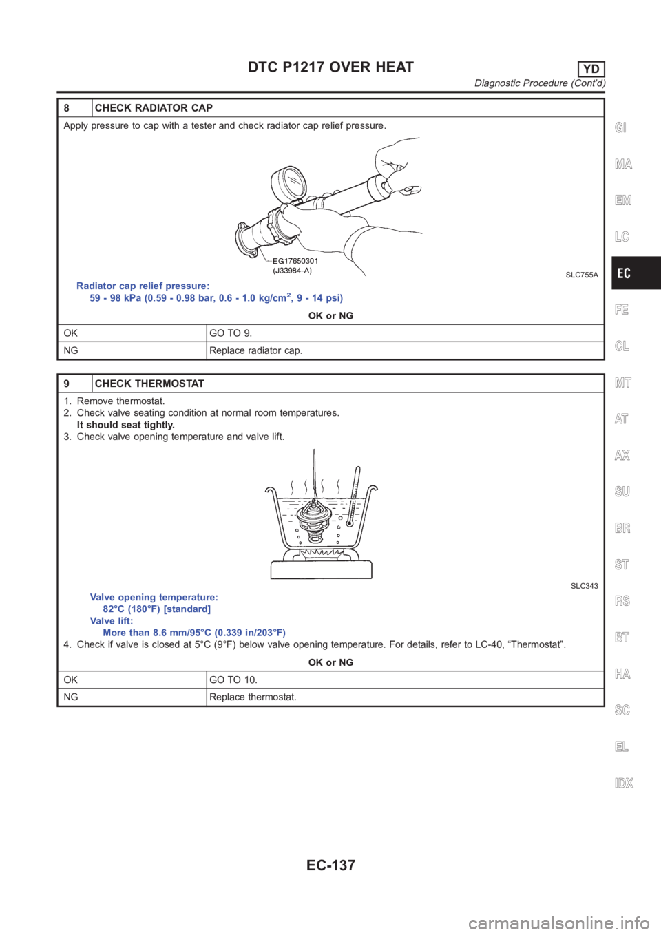
8 CHECK RADIATOR CAP
Apply pressure to cap with a tester and check radiator cap relief pressure.
SLC755A
Radiator cap relief pressure:
59 - 98 kPa (0.59 - 0.98 bar, 0.6 - 1.0 kg/cm2,9-14psi)
OK or NG
OK GO TO 9.
NG Replace radiator cap.
9 CHECK THERMOSTAT
1. Remove thermostat.
2. Check valve seating condition at normal room temperatures.
It should seat tightly.
3. Check valve opening temperature and valve lift.
SLC343
Valve opening temperature:
82°C (180°F) [standard]
Valve lift:
More than 8.6 mm/95°C (0.339 in/203°F)
4. Check if valve is closed at 5°C (9°F) below valve opening temperature. For details, refer to LC-40, “Thermostat”.
OK or NG
OK GO TO 10.
NG Replace thermostat.
GI
MA
EM
LC
FE
CL
MT
AT
AX
SU
BR
ST
RS
BT
HA
SC
EL
IDX
DTC P1217 OVER HEATYD
Diagnostic Procedure (Cont’d)
EC-137
Page 1198 of 3189
9 CHECK INTERMITTENT INCIDENT
1. Perform “TROUBLE DIAGNOSIS FOR INTERMITTENT INCIDENT”, EC-71.
INSPECTION END
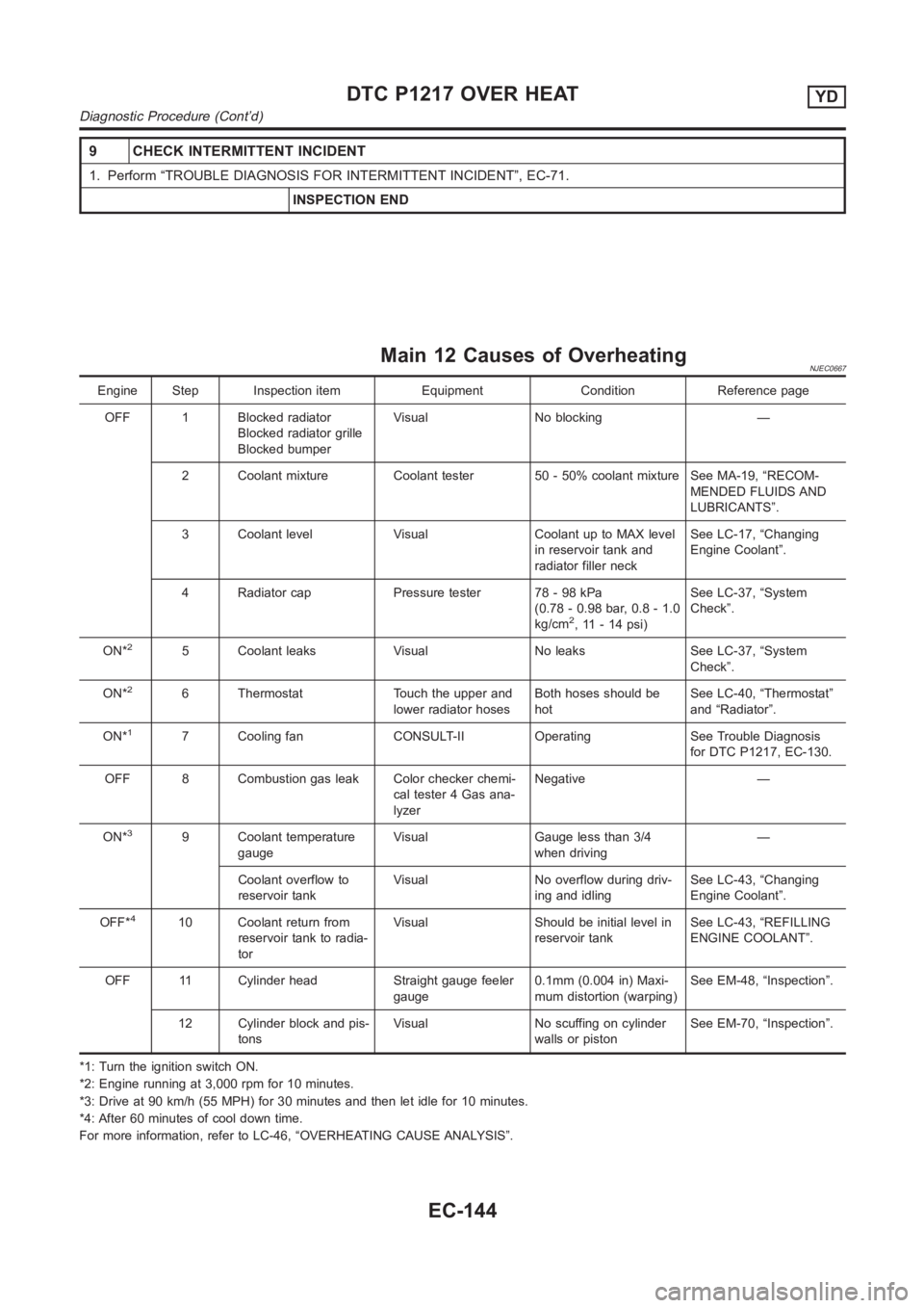
Main 12 Causes of OverheatingNJEC0667
Engine Step Inspection item Equipment Condition Reference page
OFF 1 Blocked radiator
Blocked radiator grille
Blocked bumperVisual No blocking —
2 Coolant mixture Coolant tester 50 - 50% coolant mixture See MA-19, “RECOM-
MENDED FLUIDS AND
LUBRICANTS”.
3 Coolant level Visual Coolant up to MAX level
in reservoir tank and
radiator filler neckSee LC-17, “Changing
Engine Coolant”.
4 Radiator cap Pressure tester 78 - 98 kPa
(0.78 - 0.98 bar, 0.8 - 1.0
kg/cm
2, 11 - 14 psi)See LC-37, “System
Check”.
ON*
25 Coolant leaks Visual No leaks See LC-37, “System
Check”.
ON*
26 Thermostat Touch the upper and
lower radiator hosesBoth hoses should be
hotSee LC-40, “Thermostat”
and “Radiator”.
ON*
17 Cooling fan CONSULT-II Operating See Trouble Diagnosis
for DTC P1217, EC-130.
OFF 8 Combustion gas leak Color checker chemi-
cal tester 4 Gas ana-
lyzerNegative —
ON*
39 Coolant temperature
gaugeVisual Gauge less than 3/4
when driving—
Coolant overflow to
reservoir tankVisual No overflow during driv-
ing and idlingSee LC-43, “Changing
Engine Coolant”.
OFF*
410 Coolant return from
reservoir tank to radia-
torVisual Should be initial level in
reservoir tankSee LC-43, “REFILLING
ENGINE COOLANT”.
OFF 11 Cylinder head Straight gauge feeler
gauge0.1mm (0.004 in) Maxi-
mum distortion (warping)See EM-48, “Inspection”.
12 Cylinder block and pis-
tonsVisual No scuffing on cylinder
walls or pistonSee EM-70, “Inspection”.
*1: Turn the ignition switch ON.
*2: Engine running at 3,000 rpm for 10 minutes.
*3: Drive at 90 km/h (55 MPH) for 30 minutes and then let idle for 10 minutes.
*4: After 60 minutes of cool down time.
For more information, refer to LC-46, “OVERHEATING CAUSE ANALYSIS”.
DTC P1217 OVER HEATYD
Diagnostic Procedure (Cont’d)
EC-144
Page 2948 of 3189
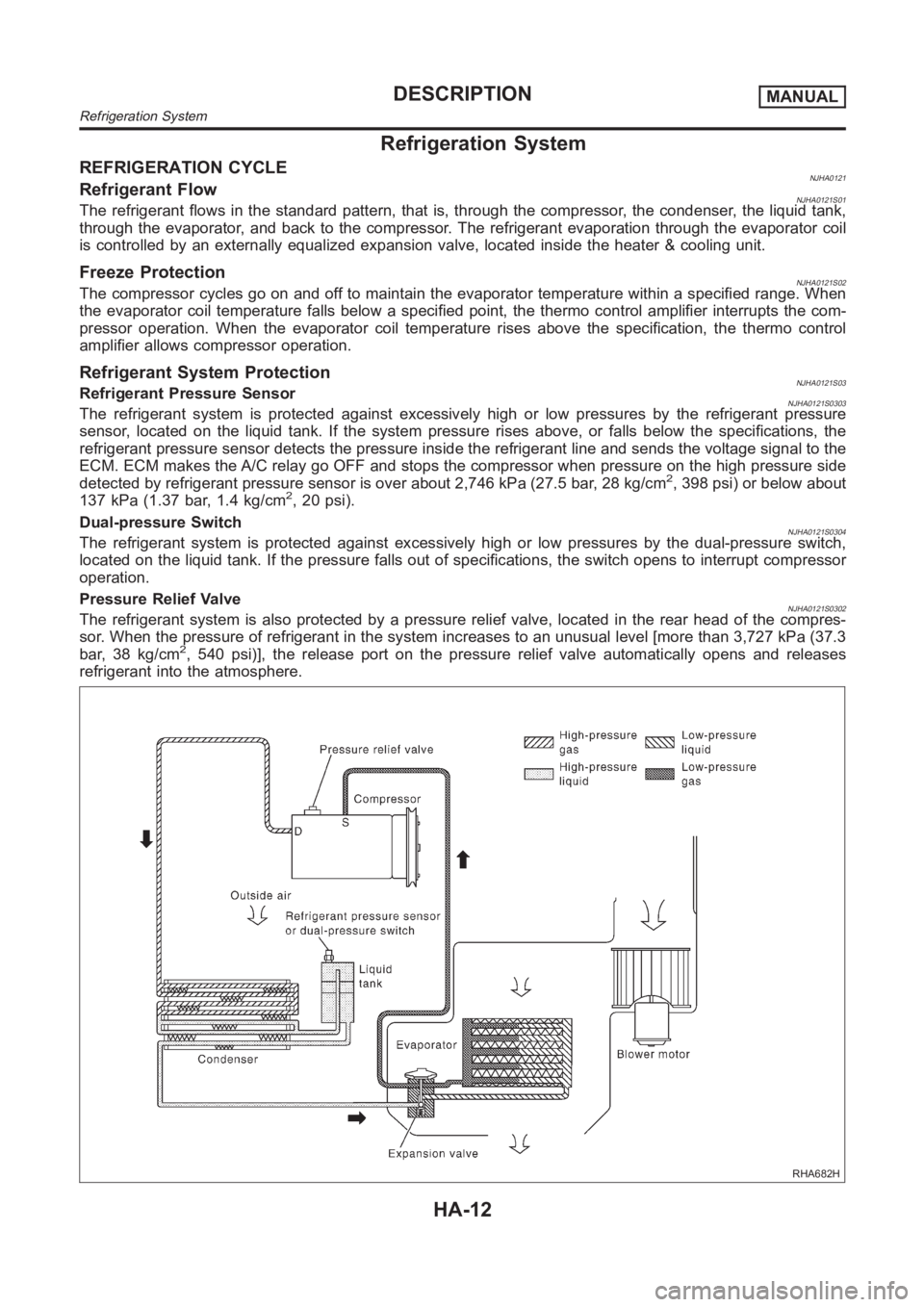
Refrigeration System
REFRIGERATION CYCLENJHA0121Refrigerant FlowNJHA0121S01The refrigerant flows in the standard pattern, that is, through the compressor, the condenser, the liquid tank,
through the evaporator, and back to the compressor. The refrigerant evaporation through the evaporator coil
is controlled by an externally equalized expansion valve, located insidethe heater & cooling unit.
Freeze ProtectionNJHA0121S02The compressor cycles go on and off to maintain the evaporator temperaturewithin a specified range. When
the evaporator coil temperature falls below a specified point, the thermocontrol amplifier interrupts the com-
pressor operation. When the evaporator coil temperature rises above the specification, the thermo control
amplifier allows compressor operation.
Refrigerant System ProtectionNJHA0121S03Refrigerant Pressure SensorNJHA0121S0303The refrigerant system is protected against excessively high or low pressures by the refrigerant pressure
sensor, located on the liquid tank. If the system pressure rises above, or falls below the specifications, the
refrigerant pressure sensor detects the pressure inside the refrigerantline and sends the voltage signal to the
ECM. ECM makes the A/C relay go OFF and stops the compressor when pressure onthe high pressure side
detected by refrigerant pressure sensor is over about 2,746 kPa (27.5 bar,28 kg/cm
2, 398 psi) or below about
137 kPa (1.37 bar, 1.4 kg/cm2, 20 psi).
Dual-pressure Switch
NJHA0121S0304The refrigerant system is protected against excessively high or low pressures by the dual-pressure switch,
located on the liquid tank. If the pressure falls out of specifications, the switch opens to interrupt compressor
operation.
Pressure Relief Valve
NJHA0121S0302The refrigerant system is also protected by a pressure relief valve, located in the rear head of the compres-
sor. When the pressure of refrigerant in the system increases to an unusuallevel [more than 3,727 kPa (37.3
bar, 38 kg/cm
2, 540 psi)], the release port on the pressure relief valve automatically opens and releases
refrigerant into the atmosphere.
RHA682H
DESCRIPTIONMANUAL
Refrigeration System
HA-12
Page 3110 of 3189
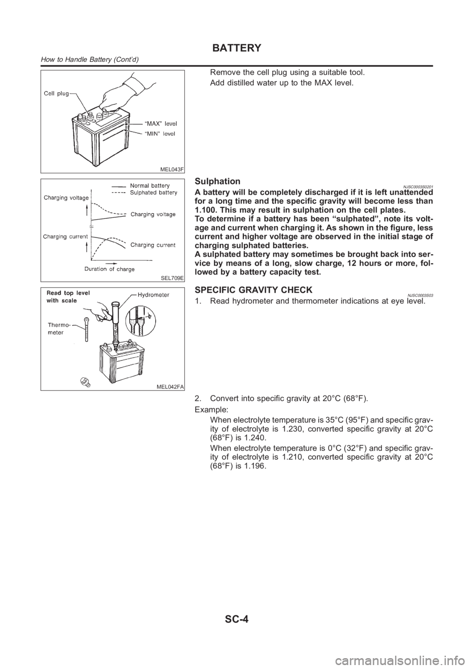
MEL043F
Remove the cell plug using a suitable tool.
Add distilled water up to the MAX level.
SEL709E
SulphationNJSC0003S0201A battery will be completely discharged if it is left unattended
for a long time and the specific gravity will become less than
1.100. This may result in sulphation on the cell plates.
To determine if a battery has been “sulphated”, note its volt-
age and current when charging it. As shown in the figure, less
current and higher voltage are observed in the initial stage of
charging sulphated batteries.
A sulphated battery may sometimes be brought back into ser-
vice by means of a long, slow charge, 12 hours or more, fol-
lowed by a battery capacity test.
MEL042FA
SPECIFIC GRAVITY CHECKNJSC0003S031. Read hydrometer and thermometer indications at eye level.
2. Convert into specific gravity at 20°C (68°F).
Example:
When electrolyte temperature is 35°C (95°F) and specific grav-
ity of electrolyte is 1.230, converted specific gravity at 20°C
(68°F) is 1.240.
When electrolyte temperature is 0°C (32°F) and specific grav-
ity of electrolyte is 1.210, converted specific gravity at 20°C
(68°F) is 1.196.
BATTERY
How to Handle Battery (Cont’d)
SC-4