2003 NISSAN ALMERA N16 turning light
[x] Cancel search: turning lightPage 1373 of 3189
SMT587
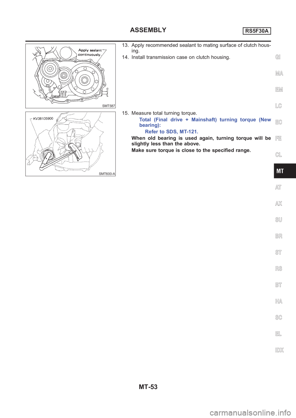
13. Apply recommended sealant to mating surface of clutch hous-
ing.
14. Install transmission case on clutch housing.
SMT600-A
15. Measure total turning torque.
Total (Final drive + Mainshaft) turning torque (New
bearing):
Refer to SDS, MT-121.
When old bearing is used again, turning torque will be
slightly less than the above.
Make sure torque is close to the specified range.
GI
MA
EM
LC
EC
FE
CL
AT
AX
SU
BR
ST
RS
BT
HA
SC
EL
IDX
ASSEMBLYRS5F30A
MT-53
Page 1407 of 3189
SMT742D
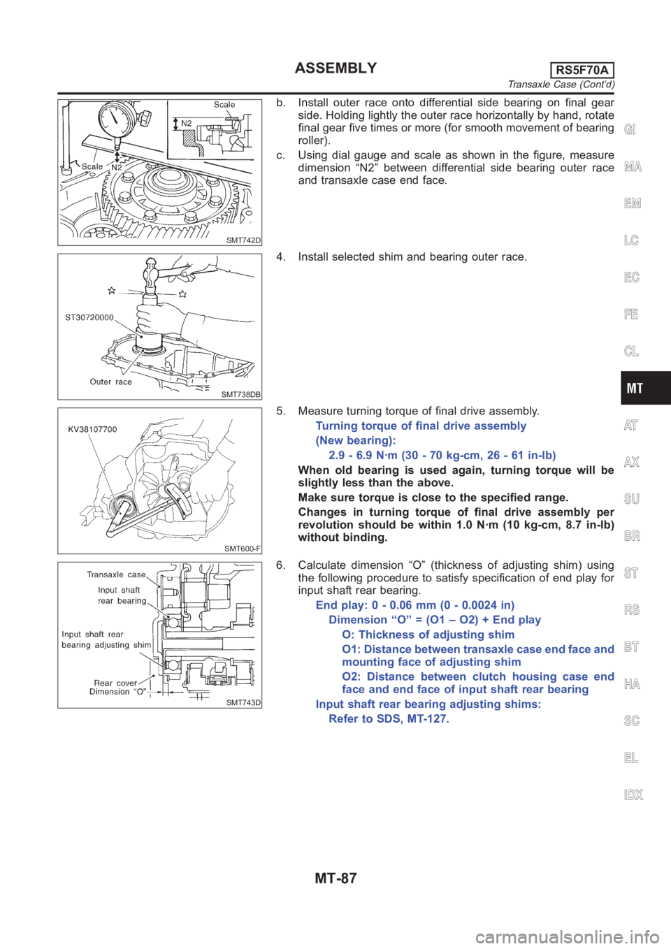
b. Install outer race onto differential side bearing on final gear
side. Holding lightly the outer race horizontally by hand, rotate
final gear five times or more (for smooth movement of bearing
roller).
c. Using dial gauge and scale as shown in the figure, measure
dimension “N2” between differential side bearing outer race
and transaxle case end face.
SMT738DB
4. Install selected shim and bearing outer race.
SMT600-F
5. Measure turning torque of final drive assembly.
Turning torque of final drive assembly
(New bearing):
2.9 - 6.9 N·m (30 - 70 kg-cm, 26 - 61 in-lb)
When old bearing is used again, turning torque will be
slightly less than the above.
Make sure torque is close to the specified range.
Changes in turning torque of final drive assembly per
revolution should be within 1.0 N·m (10 kg-cm, 8.7 in-lb)
without binding.
SMT743D
6. Calculate dimension “O” (thickness of adjusting shim) using
the following procedure to satisfy specification of end play for
input shaft rear bearing.
End play: 0 - 0.06 mm (0 - 0.0024 in)
Dimension “O” = (O1 – O2) + End play
O: Thickness of adjusting shim
O1: Distance between transaxle case end face and
mounting face of adjusting shim
O2: Distance between clutch housing case end
face and end face of input shaft rear bearing
Input shaft rear bearing adjusting shims:
Refer to SDS, MT-127.
GI
MA
EM
LC
EC
FE
CL
AT
AX
SU
BR
ST
RS
BT
HA
SC
EL
IDX
ASSEMBLYRS5F70A
Transaxle Case (Cont’d)
MT-87
Page 1437 of 3189
SMT070A
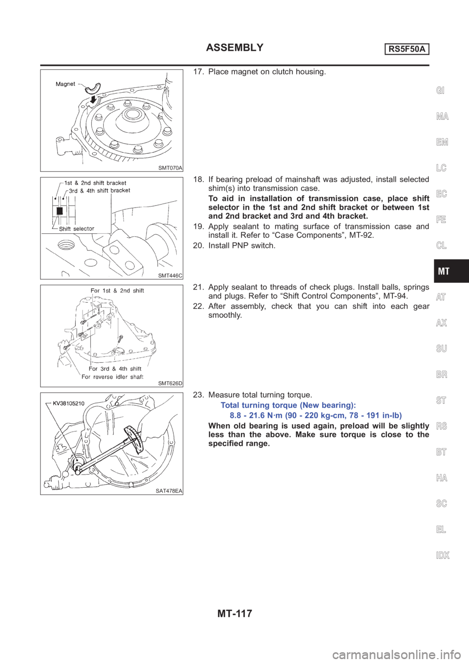
17. Place magnet on clutch housing.
SMT446C
18. If bearing preload of mainshaft was adjusted, install selected
shim(s) into transmission case.
To aid in installation of transmission case, place shift
selector in the 1st and 2nd shift bracket or between 1st
and 2nd bracket and 3rd and 4th bracket.
19. Apply sealant to mating surface of transmission case and
install it. Refer to “Case Components”, MT-92.
20. Install PNP switch.
SMT626D
21. Apply sealant to threads of check plugs. Install balls, springs
and plugs. Refer to “Shift Control Components”, MT-94.
22. After assembly, check that you can shift into each gear
smoothly.
SAT478EA
23. Measure total turning torque.
Total turning torque (New bearing):
8.8 - 21.6 N·m (90 - 220 kg-cm, 78 - 191 in-lb)
When old bearing is used again, preload will be slightly
less than the above. Make sure torque is close to the
specified range.
GI
MA
EM
LC
EC
FE
CL
AT
AX
SU
BR
ST
RS
BT
HA
SC
EL
IDX
ASSEMBLYRS5F50A
MT-117
Page 1461 of 3189
PRECAUTIONS
AT-5
D
E
F
G
H
I
J
K
L
MA
B
AT
PRECAUTIONSPFP:00001
Precautions for Supplemental Restraint System (SRS) “AIR BAG” and “SEAT
BELT PRE-TENSIONER”
ECS007N3
The Supplemental Restraint System such as “AIR BAG” and “SEAT BELT PRE-TENSIONER”, used along
with a front seat belt, helps to reduce the risk or severity of injury to the driver and front passenger for certain
types of collision. Information necessary to service the system safely is included in the SRS and SB section of
this Service Manual.
WARNING:
●To avoid rendering the SRS inoperative, which could increase the risk of personal injury or death
in the event of a collision which would result in air bag inflation, all maintenance must be per-
formed by an authorized NISSAN/INFINITI dealer.
●Improper maintenance, including incorrect removal and installation of the SRS, can lead to per-
sonal injury caused by unintentional activation of the system. For removal of Spiral Cable and Air
Bag Module, see the SRS section.
●Do not use electrical test equipment on any circuit related to the SRS unless instructed to in this
Service Manual. SRS wiring harnesses can be identified by yellow and/or orange harness connec-
tors.
Precautions for On Board Diagnostic (EURO-OBD) System of A/T and Engine —
Euro-OBD —
ECS007N4
The ECM has an on board diagnostic system. It will light up the malfunction indicator (MI) to warn the driver of
a malfunction causing emission deterioration.
CAUTION:
●Be sure to turn the ignition switch “OFF” and disconnect the negative battery terminal before any
repair or inspection work. The open/short circuit of related switches, sensors, solenoid valves,
etc. will cause the MI to light up.
●Be sure to connect and lock the connectors securely after work. A loose (unlocked) connector will
cause the MI to light up due to an open circuit. (Be sure the connector is free from water, grease,
dirt, bent terminals, etc.)
●Be sure to route and secure the harnesses properly after work. Interference of the harness with a
bracket, etc. may cause the MI to light up due to a short circuit.
●Be sure to connect rubber tubes properly after work. A misconnected or disconnected rubber tube
may cause the MI to light up due to a malfunction of the EGR system or fuel injection system, etc.
●Be sure to erase the unnecessary malfunction information (repairs completed) from the TCM and
ECM before returning the vehicle to the customer.
Precautions for Trouble DiagnosisECS007N5
CAN SYSTEM
●Do not apply voltage of 7.0V or higher to the measurement terminals.
●Use the tester with its open terminal voltage being 7.0V or less.
Precautions for Harness RepairECS007N6
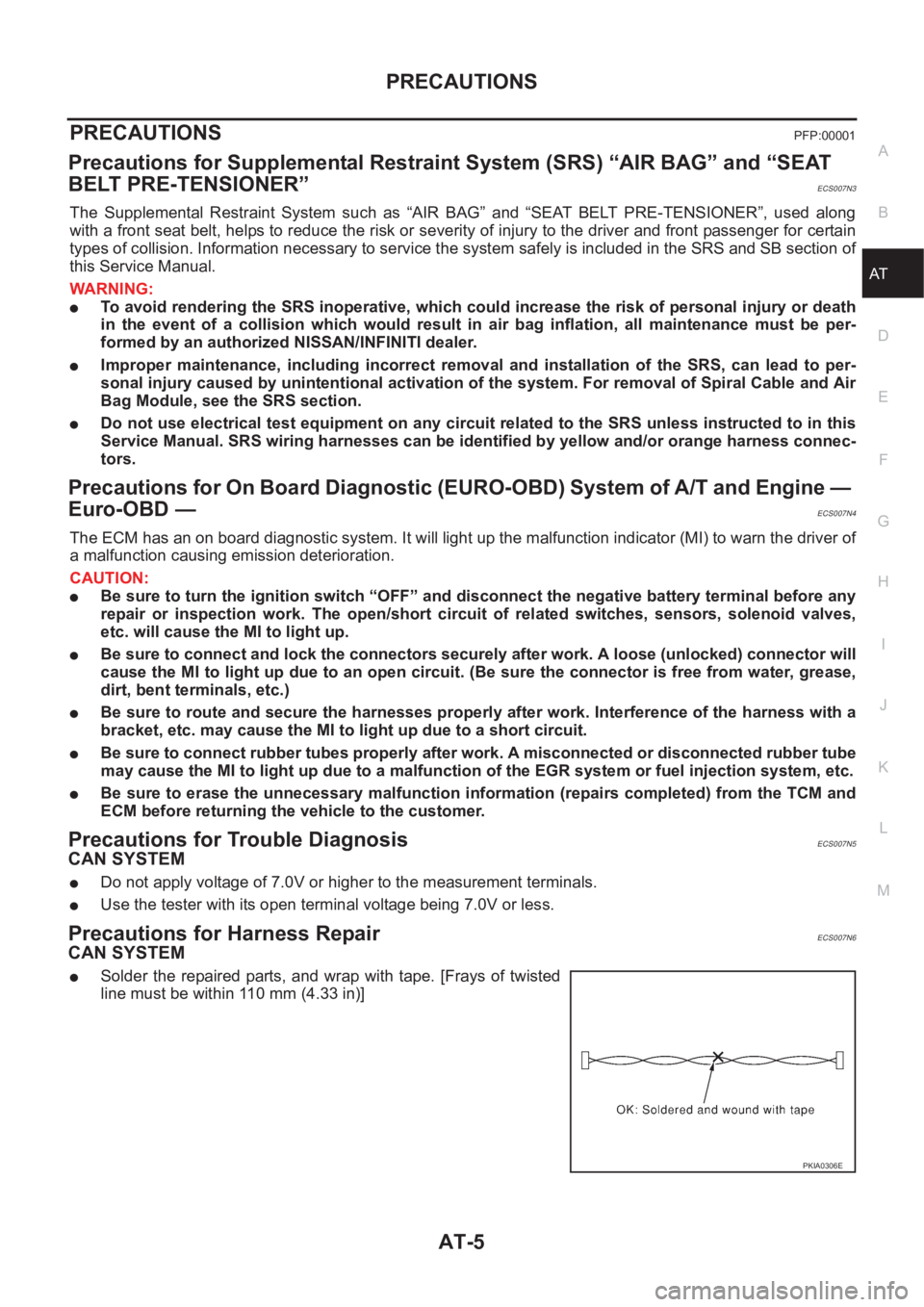
CAN SYSTEM
●Solder the repaired parts, and wrap with tape. [Frays of twisted
line must be within 110 mm (4.33 in)]
PKIA0306E
Page 1689 of 3189
![NISSAN ALMERA N16 2003 Electronic Repair Manual TROUBLE DIAGNOSES FOR SYMPTOMS
AT-233
[EURO-OBD]
D
E
F
G
H
I
J
K
L
MA
B
AT
15. Engine Speed Does Not Return To Idle (Light Braking D4→ D3 )ECS007QG
SYMPTOM:
●Engine speed does not smoothly return](/manual-img/5/57350/w960_57350-1688.png "NISSAN ALMERA N16 2003 Electronic Repair Manual TROUBLE DIAGNOSES FOR SYMPTOMS
AT-233
[EURO-OBD]
D
E
F
G
H
I
J
K
L
MA
B
AT
15. Engine Speed Does Not Return To Idle (Light Braking D4→ D3 )ECS007QG
SYMPTOM:
●Engine speed does not smoothly return")
TROUBLE DIAGNOSES FOR SYMPTOMS
AT-233
[EURO-OBD]
D
E
F
G
H
I
J
K
L
MA
B
AT
15. Engine Speed Does Not Return To Idle (Light Braking D4→ D3 )ECS007QG
SYMPTOM:
●Engine speed does not smoothly return to idle when A/T shifts from D4 to D3 .
●Vehicle does not decelerate by engine brake when turning overdrive control switch OFF.
●Vehicle does not decelerate by engine brake when shifting A/T from “D” to “2” position.
1.CHECK SELF-DIAGNOSTIC RESULTS
Does self-diagnosis show damage to overrun clutch solenoid valve
circuit after cruise test?
Ye s o r N O
Yes >> Check overrun clutch solenoid valve circuit. Refer to AT-
187, "DTC P1760 OVERRUN CLUTCH SOLENOID
VA LV E" .
No >> GO TO 2
2.CHECK THROTTLE POSITION SENSOR*
*: This sensor means accelerator pedal position (APP) sensor.
Refer to AT- 1 8 1 , "
DTC P1705 ACCELERATOR PEDAL POSITION
(APP) SENSOR" .
OK or NG
OK >> GO TO 3
NG >> Repair or replace accelerator pedal position (APP) sen-
sor. (AT- 1 8 1 , "
DTC P1705 ACCELERATOR PEDAL
POSITION (APP) SENSOR" )
3.CHECK A/T FLUID CONDITION
1. Remove oil pan, refer to AT- 4 0 6 , "
REMOVAL" .
2. Check A/T fluid condition.
OK or NG
OK >> GO TO 4
NG >> GO TO 6
SCIA0774E
MCIB9006E
SAT171B
Page 1784 of 3189
![NISSAN ALMERA N16 2003 Electronic Repair Manual AT-328
[EXC.F/EURO-OBD]
TROUBLE DIAGNOSES FOR SYMPTOMS
5. DETECT MALFUNCTIONING ITEM
1. Remove control valve assembly. Refer to AT- 4 0 6 , "
Control Valve Assembly and Accumulators" .
2. Ch](/manual-img/5/57350/w960_57350-1783.png "NISSAN ALMERA N16 2003 Electronic Repair Manual AT-328
[EXC.F/EURO-OBD]
TROUBLE DIAGNOSES FOR SYMPTOMS
5. DETECT MALFUNCTIONING ITEM
1. Remove control valve assembly. Refer to AT- 4 0 6 , \"
Control Valve Assembly and Accumulators\" .
2. Ch")
AT-328
[EXC.F/EURO-OBD]
TROUBLE DIAGNOSES FOR SYMPTOMS
5. DETECT MALFUNCTIONING ITEM
1. Remove control valve assembly. Refer to AT- 4 0 6 , "
Control Valve Assembly and Accumulators" .
2. Check the following items:
–Torque converter clutch control valve
–Pilot valve
–Pilot filter
3. Disassemble A/T.
4. Check torque converter and oil pump assembly.
OK or NG
OK >> GO TO 4
NG >> Repair or replace damaged parts.
14. Lock-up Is Not ReleasedECS007RD
SYMPTOM:
Lock-up is not released when accelerator pedal is released.
1. CHECK THROTTLE POSITION SENSOR* CIRCUIT
*: This sensor means accelerator pedal position (APP) sensor.
With CONSULT-II
Does “TCM INPUT SIGNALS” in “DATA MONITOR” show damage throttle position sensor circuit?
Without CONSULT-II
Does self-diagnosis show damage to throttle position sensor circuit?
Ye s o r N o
Yes >> Check throttle position sensor circuit. Refer to AT- 3 3 3 ,
"21. TCM Self-diagnosis Does Not Activate (PNP &
Overdrive Control Switches, and Throttle Position Sen-
sor Circuit Checks)" .
No >> GO TO 2
2. CHECK SYMPTOM
Check again.
OK or NG
OK >>INSPECTION END
NG >> 1. Perform TCM input/output signal inspection.
2. If NG, recheck TCM pin terminals for damage or loose connection with harness connector.
15. Engine Speed Does Not Return To Idle (Light Braking D4→ D3 )ECS007RE
SYMPTOM:
●Engine speed does not smoothly return to idle when A/T shifts from D4 to D3 .
●Vehicle does not decelerate by engine brake when turning overdrive control switch OFF.
●Vehicle does not decelerate by engine brake when shifting A/T from “D” to “2” position.
SCIA0706E
Page 1951 of 3189
![NISSAN ALMERA N16 2003 Electronic Repair Manual ASSEMBLY
AT-495
[ALL]
D
E
F
G
H
I
J
K
L
MA
B
AT
5. Attach dial indicator on differential case at transmission case
side.
6. Insert Tool into differential side gear from converter housing.
7. M](/manual-img/5/57350/w960_57350-1950.png "NISSAN ALMERA N16 2003 Electronic Repair Manual ASSEMBLY
AT-495
[ALL]
D
E
F
G
H
I
J
K
L
MA
B
AT
5. Attach dial indicator on differential case at transmission case
side.
6. Insert Tool into differential side gear from converter housing.
7. M")
ASSEMBLY
AT-495
[ALL]
D
E
F
G
H
I
J
K
L
MA
B
AT
5. Attach dial indicator on differential case at transmission case
side.
6. Insert Tool into differential side gear from converter housing.
7. Move Tool up and down and measure dial indicator deflection.
8. Select proper thickness of differential side bearing adjusting
shim(s) using SDS table as a guide.
9. Remove converter housing from transmission case.
10. Remove final drive assembly from transmission case.
11. Remove differential side bearing outer race from transmission
case.
12. Reinstall differential side bearing outer race and shim(s)
selected from SDS table on transmission case.
13. Reinstall converter housing on transmission case and tighten
transmission case fixing bolts to the specified torque. Refer to
AT- 4 1 3 , "
OVERHAUL" .
14. Insert Tool into differential case and measure turning torque of
final drive assembly.
●Turn final drive assembly in both directions several times
to seat bearing rollers correctly.
●When old bearing is used again, turning torque will be
slightly less than the above.
●Make sure torque is close to the specified range.
REDUCTION PINION GEAR BEARING PRELOAD
●Be sure to remove final drive assembly before doing this proce-
dure.
●Using caliper and straightedge, calculate a dimension “T”
(adjuster shim thickness) in the right figure by the following for-
mula and adjust the inspection standard for pre load (rotating
slide torque) as shown below.Differential side bearing preload “T”:
0.04 - 0.09 mm (0.0016 - 0.0035 in)
Differential side bearing adjusting shim:
Refer to AT- 5 1 5 , "
SERVICE DATA AND SPECIFICA-
TIONS (SDS)" .
AAT947
AAT477
Turning torque of final drive assembly (New bearing):
0.49 - 1.08 N-m (5.0 - 11.0 kg-cm, 4.3 - 9.5 in-lb)
AAT466
T = A − E
Inspection standard for preload:
0.1 - 0.69 N-m (1.1 - 7.0 kg-cm, 0.95 - 6.08 in-lb)
SAT876J
Page 2478 of 3189
![NISSAN ALMERA N16 2003 Electronic Repair Manual 4. Select the desired part to be diagnosed on the “SELECT TES-
T ITEM” screen.
Data monitor item (KEY REMINDER)
Monitored item Description
IGNITION SW Indicates [ON/OFF] condition of ignition swit](/manual-img/5/57350/w960_57350-2477.png "NISSAN ALMERA N16 2003 Electronic Repair Manual 4. Select the desired part to be diagnosed on the “SELECT TES-
T ITEM” screen.
Data monitor item (KEY REMINDER)
Monitored item Description
IGNITION SW Indicates [ON/OFF] condition of ignition swit")
4. Select the desired part to be diagnosed on the “SELECT TES-
T ITEM” screen.
Data monitor item (KEY REMINDER)
Monitored item Description
IGNITION SW Indicates [ON/OFF] condition of ignition switch.
KEY IN DETECT Indicates [ON/OFF] condition of electronic key switch.
DR DOOR SW Indicates [ON/OFF] condition of front door switch (driver side).
CDL LOCK SW Indicates [ON/OFF] condition of door lock/unlock switch.
RKE LOCK Indicates [ON/OFF] condition of lock signal from remote controller.
Data monitor item (Light warning chime)
Monitored item Description
IGN ON SW Indicates [ON/OFF] condition of ignition switch.
DR DOOR SW Indicates [ON/OFF] condition of front door switch (driver side).
TAIL LAMP ON Indicates [ON/OFF] condition of lighting switch.
SYMPTOM CHARTNJEL0551S02First perform the “SELF-DIAG RESULTS” in “SMART ENTRANCE”
with CONSULT-II, when perform the each trouble diagnosis.
Symptom Diagnoses/Service procedure Reference page
Light warning chime does not activate.Power supply and ground circuit checkEL-143, “Power Supply
and Ground Circuit
Check”
Lighting switch checkEL-144, “Lighting Switch
Input Signal Check”
Front door switch (driver side) checkEL-150, “Front Door
Switch (Driver side)
Check”
Key warning chime does not activate.Power supply and ground circuit checkEL-143, “Power Supply
and Ground Circuit
Check”
Key switch insert signal checkEL-147, “Key Switch
Insert Signal Check”
Front door switch (driver side) checkEL-150, “Front Door
Switch (Driver side)
Check”
All warning chimes do not activate. Power supply and ground circuit checkEL-143, “Power Supply
and Ground Circuit
Check”
With the ignition switch turned OFF and the
door closed (driver side) turning the lighting
switch ON (1st) activates the chime.Front door switch (driver side) checkEL-150, “Front Door
Switch (Driver side)
Check”
WARNING CHIME
Trouble Diagnoses/QG and YD Engine Models with Common Rail (Cont’d)
EL-142