2003 NISSAN ALMERA N16 Auto AC
[x] Cancel search: Auto ACPage 2842 of 3189
Cause (condition) -:While driving ooo:Display Driving condition Remarks (correction, etc.)
Precautions
for drivingJust after the engine is startedIf the vehicle is driven off just after the
engine is started when the gyroscope
(angular speed sensor) correction is
not completed, the vehicle can lose its
direction and may have deviated from
the correct location.Wait for a short while before driv-
ing after starting the engine.
Continuous driving without stoppingWhen driving long distances without
stopping, direction errors may
accumulate, and the current-location
mark may deviate from the correct
road.Stop and adjust the orientation.
Abusive drivingSpinning the wheels or engaging in
other kinds of abusive driving may
result in the system being unable to
perform correct detection, and may
cause the vehicle mark to deviate from
the correct road.If after travelling about 10 km (6
miles) the correct location has not
been restored, perform location
correction and, if necessary,
direction correction.
How to cor-
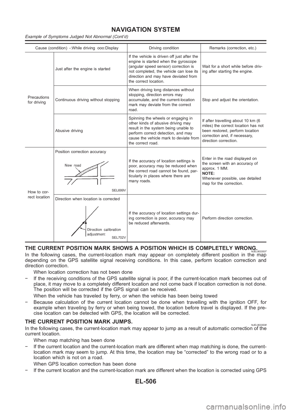
rect locationPosition correction accuracy
SEL699V
If the accuracy of location settings is
poor, accuracy may be reduced when
the correct road cannot be found, par-
ticularly in places where there are
many roads.Enter in the road displayed on
the screen with an accuracy of
approx. 1 MM.
NOTE:
Whenever possible, use detailed
map for the correction.
Direction when location is corrected
SEL702V
If the accuracy of location settings dur-
ing correction is poor, accuracy may
be reduced afterwards.Perform direction correction.
THE CURRENT POSITION MARK SHOWS A POSITION WHICH IS COMPLETELY WRONG.NJEL0633S07In the following cases, the current-location mark may appear on completely different position in the map
depending on the GPS satellite signal receiving conditions. In this case,perform location correction and
direction correction.
When location correction has not been done
− If the receiving conditions of the GPS satellite signal is poor, if the current-location mark becomes out of
place, it may move to a completely different location and not come back if location correction is not done.
The position will be corrected if the GPS signal can be received.
When the vehicle has traveled by ferry, or when the vehicle has been being towed
− Because calculation of the current location cannot be done when travelling with the ignition OFF, for
example when traveling by ferry or when being towed, the location before travel is displayed. If the pre-
cise location can be detected with GPS, the location will be corrected.
THE CURRENT POSITION MARK JUMPS.NJEL0633S08In the following cases, the current-location mark may appear to jump as a result of automatic correction of the
current location.
When map matching has been done
− If the current location and the current-location mark are different whenmap matching is done, the current-
location mark may seem to jump. At this time, the location may be “corrected” to the wrong road or to a
location which is not on a road.
When GPS location correction has been done
− If the current location and the current-location mark are different whenthe location is corrected using GPS
NAVIGATION SYSTEM
Example of Symptoms Judged Not Abnormal (Cont’d)
EL-506
Page 2942 of 3189
Precautions for Service EquipmentNJHA0117RECOVERY/RECYCLING EQUIPMENTNJHA0117S01Follow the manufacturer’s instructions for machine operation and
machine maintenance. Never introduce any refrigerant other than
that specified into the machine.
ELECTRONIC LEAK DETECTORNJHA0117S02Follow the manufacture’s instructions for tester operation and
tester maintenance.
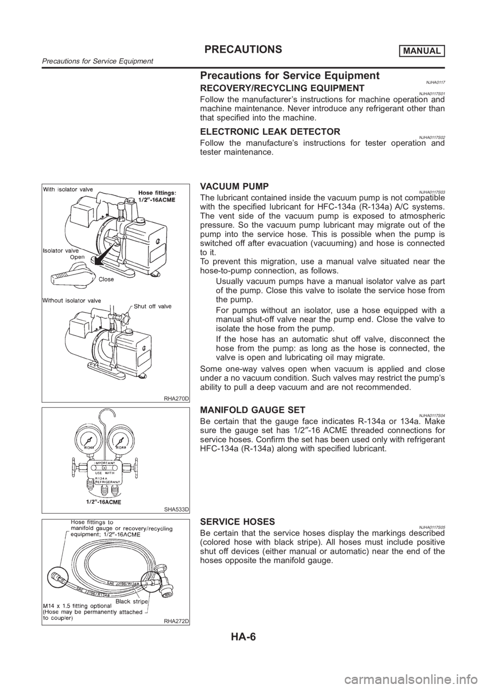
RHA270D
VACUUM PUMPNJHA0117S03The lubricant contained inside the vacuum pump is not compatible
with the specified lubricant for HFC-134a (R-134a) A/C systems.
The vent side of the vacuum pump is exposed to atmospheric
pressure. So the vacuum pump lubricant may migrate out of the
pump into the service hose. This is possible when the pump is
switched off after evacuation (vacuuming) and hose is connected
to it.
To prevent this migration, use a manual valve situated near the
hose-to-pump connection, as follows.
Usually vacuum pumps have a manual isolator valve as part
of the pump. Close this valve to isolate the service hose from
the pump.
For pumps without an isolator, use a hose equipped with a
manual shut-off valve near the pump end. Close the valve to
isolate the hose from the pump.
If the hose has an automatic shut off valve, disconnect the
hose from the pump: as long as the hose is connected, the
valve is open and lubricating oil may migrate.
Some one-way valves open when vacuum is applied and close
under a no vacuum condition. Such valves may restrict the pump’s
ability to pull a deep vacuum and are not recommended.
SHA533D
MANIFOLD GAUGE SETNJHA0117S04Be certain that the gauge face indicates R-134a or 134a. Make
sure the gauge set has 1/2″-16 ACME threaded connections for
service hoses. Confirm the set has been used only with refrigerant
HFC-134a (R-134a) along with specified lubricant.
RHA272D
SERVICE HOSESNJHA0117S05Be certain that the service hoses display the markings described
(colored hose with black stripe). All hoses must include positive
shut off devices (either manual or automatic) near the end of the
hoses opposite the manifold gauge.
PRECAUTIONSMANUAL
Precautions for Service Equipment
HA-6
Page 2948 of 3189
Refrigeration System
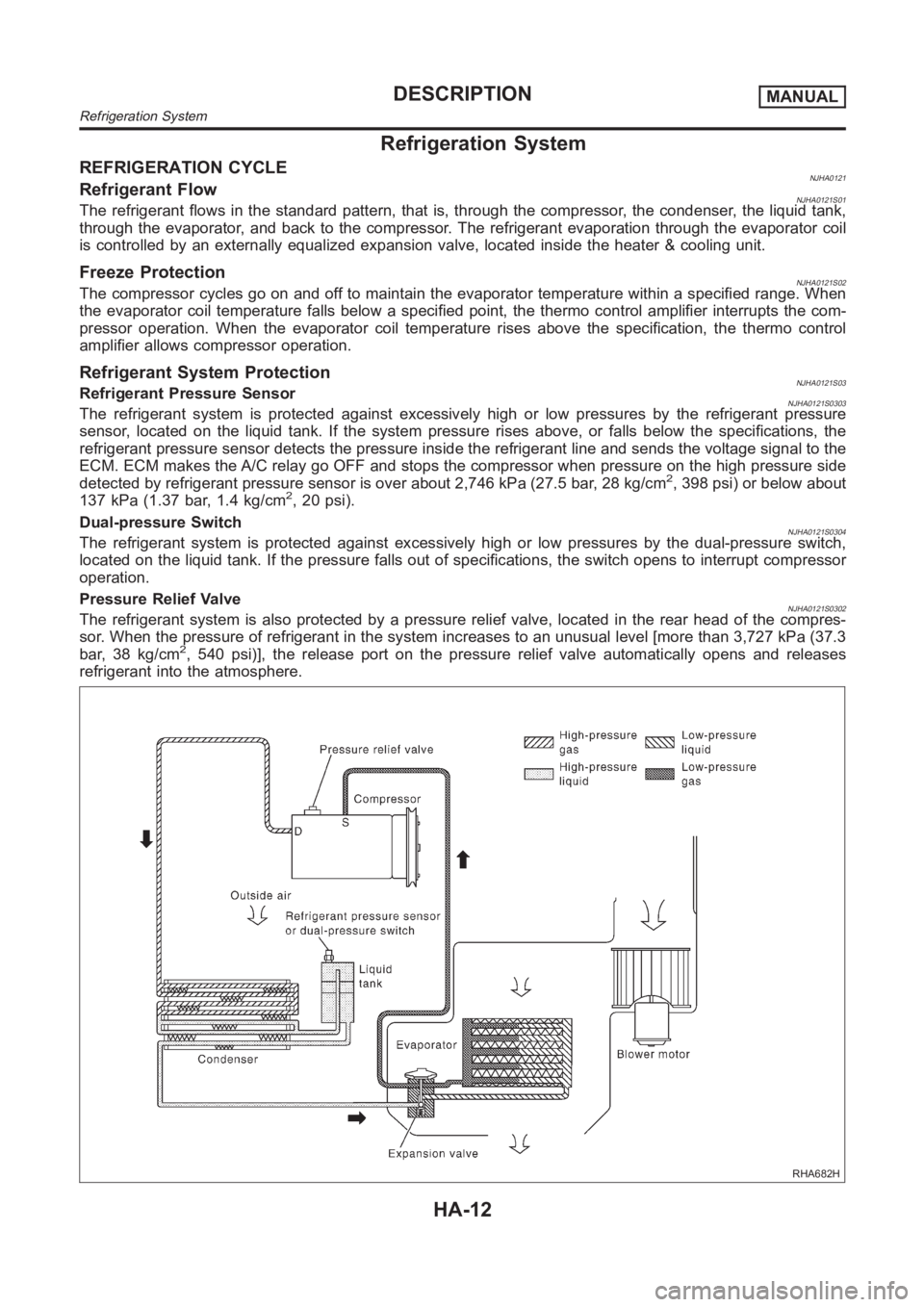
REFRIGERATION CYCLENJHA0121Refrigerant FlowNJHA0121S01The refrigerant flows in the standard pattern, that is, through the compressor, the condenser, the liquid tank,
through the evaporator, and back to the compressor. The refrigerant evaporation through the evaporator coil
is controlled by an externally equalized expansion valve, located insidethe heater & cooling unit.
Freeze ProtectionNJHA0121S02The compressor cycles go on and off to maintain the evaporator temperaturewithin a specified range. When
the evaporator coil temperature falls below a specified point, the thermocontrol amplifier interrupts the com-
pressor operation. When the evaporator coil temperature rises above the specification, the thermo control
amplifier allows compressor operation.
Refrigerant System ProtectionNJHA0121S03Refrigerant Pressure SensorNJHA0121S0303The refrigerant system is protected against excessively high or low pressures by the refrigerant pressure
sensor, located on the liquid tank. If the system pressure rises above, or falls below the specifications, the
refrigerant pressure sensor detects the pressure inside the refrigerantline and sends the voltage signal to the
ECM. ECM makes the A/C relay go OFF and stops the compressor when pressure onthe high pressure side
detected by refrigerant pressure sensor is over about 2,746 kPa (27.5 bar,28 kg/cm
2, 398 psi) or below about
137 kPa (1.37 bar, 1.4 kg/cm2, 20 psi).
Dual-pressure Switch
NJHA0121S0304The refrigerant system is protected against excessively high or low pressures by the dual-pressure switch,
located on the liquid tank. If the pressure falls out of specifications, the switch opens to interrupt compressor
operation.
Pressure Relief Valve
NJHA0121S0302The refrigerant system is also protected by a pressure relief valve, located in the rear head of the compres-
sor. When the pressure of refrigerant in the system increases to an unusuallevel [more than 3,727 kPa (37.3
bar, 38 kg/cm
2, 540 psi)], the release port on the pressure relief valve automatically opens and releases
refrigerant into the atmosphere.
RHA682H
DESCRIPTIONMANUAL
Refrigeration System
HA-12
Page 3074 of 3189
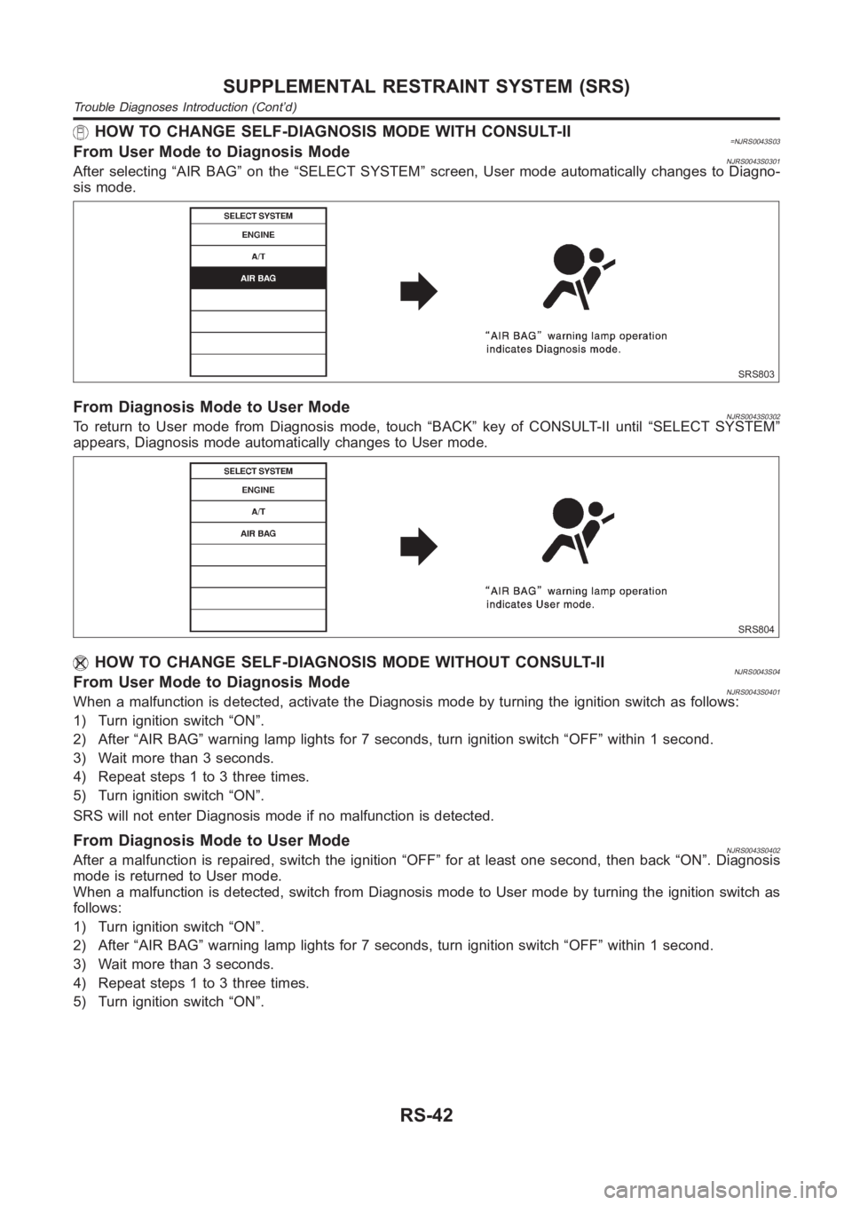
HOW TO CHANGE SELF-DIAGNOSIS MODE WITH CONSULT-II=NJRS0043S03From User Mode to Diagnosis ModeNJRS0043S0301After selecting “AIR BAG” on the “SELECT SYSTEM” screen, User mode automatically changes to Diagno-
sis mode.
SRS803
From Diagnosis Mode to User ModeNJRS0043S0302To return to User mode from Diagnosis mode, touch “BACK” key of CONSULT-II until “SELECT SYSTEM”
appears, Diagnosis mode automatically changes to User mode.
SRS804
HOW TO CHANGE SELF-DIAGNOSIS MODE WITHOUT CONSULT-IINJRS0043S04From User Mode to Diagnosis ModeNJRS0043S0401When a malfunction is detected, activate the Diagnosis mode by turning theignition switch as follows:
1) Turn ignition switch “ON”.
2) After “AIR BAG” warning lamp lights for 7 seconds, turn ignition switch “OFF” within 1 second.
3) Wait more than 3 seconds.
4) Repeat steps 1 to 3 three times.
5) Turn ignition switch “ON”.
SRS will not enter Diagnosis mode if no malfunction is detected.
From Diagnosis Mode to User ModeNJRS0043S0402After a malfunction is repaired, switch the ignition “OFF” for at least onesecond, then back “ON”. Diagnosis
mode is returned to User mode.
When a malfunction is detected, switch from Diagnosis mode to User mode by turning the ignition switch as
follows:
1) Turn ignition switch “ON”.
2) After “AIR BAG” warning lamp lights for 7 seconds, turn ignition switch “OFF” within 1 second.
3) Wait more than 3 seconds.
4) Repeat steps 1 to 3 three times.
5) Turn ignition switch “ON”.
SUPPLEMENTAL RESTRAINT SYSTEM (SRS)
Trouble Diagnoses Introduction (Cont’d)
RS-42
Page 3176 of 3189
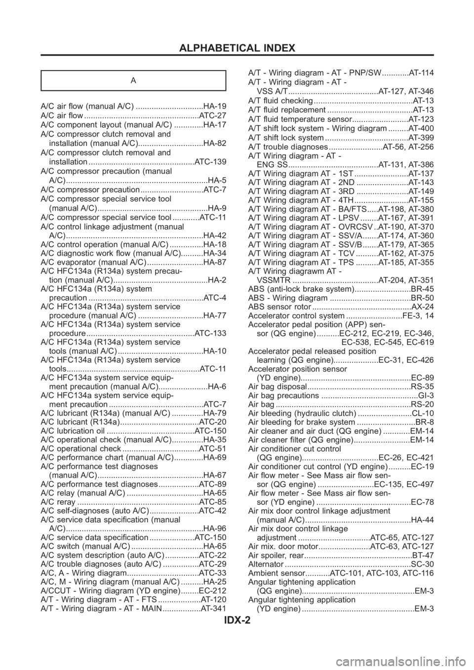
A
A/C air flow (manual A/C) ..............................HA-19
A/C air flow <0011001100110011001100110011001100110011001100110011001100110011001100110011001100110011001100110011001100110011001100110011001100110011001100110011001100110011001100110011001100110011001100110011001100
110024>�TC-27
A/C component layout (manual A/C) .............HA-17
A/C compressor clutch removal and
installation (manual A/C).............................HA-82
A/C compressor clutch removal and
installation ...............................................ATC-139
A/C compressor precaution (manual
A/C) <0011001100110011001100110011001100110011001100110011001100110011001100110011001100110011001100110011001100110011001100110011001100110011001100110011001100110011001100110011001100110011001100110011001100
1100110011001100110011001100110011[....HA-5
A/C compressor precaution ............................ATC-7
A/C compressor special service tool
(manual A/C) .................................................HA-9
A/C compressor special service tool ............ATC-11
A/C control linkage adjustment (manual
A/C) <0011001100110011001100110011001100110011001100110011001100110011001100110011001100110011001100110011001100110011001100110011001100110011001100110011001100110011001100110011001100110011001100110011001100
1100110011001100110011001100110011[..HA-42
A/C control operation (manual A/C) ...............HA-18
A/C diagnostic work flow (manual A/C)..........HA-34
A/C evaporator (manual A/C) .........................HA-87
A/C HFC134a (R134a) system precau-
tion (manual A/C) ..........................................HA-2
A/C HFC134a (R134a) system
precaution <0011001100110011001100110011001100110011001100110011001100110011001100110011001100110011001100110011001100110011001100110011001100110011001100110011001100110011001100110011001100110011001100110011001100
110024>�TC-4
A/C HFC134a (R134a) system service
procedure (manual A/C) .............................HA-77
A/C HFC134a (R134a) system service
procedure ................................................ATC-133
A/C HFC134a (R134a) system service
tools (manual A/C) ......................................HA-10
A/C HFC134a (R134a) system service
tools<0011001100110011001100110011001100110011001100110011001100110011001100110011001100110011001100110011001100110011001100110011001100110011001100110011001100110011001100110011001100110011001100110011001100
110011001100110011001100110011[.ATC-11
A/C HFC134a system service equip-
ment precaution (manual A/C)......................HA-6
A/C HFC134a system service equip-
ment precaution ..........................................ATC-7
A/C lubricant (R134a) (manual A/C) ..............HA-79
A/C lubricant (R134a) ...................................ATC-20
A/C lubrication oil .......................................ATC-150
A/C operational check (manual A/C)..............HA-35
A/C operational check ..................................ATC-51
A/C performance chart (manual A/C).............HA-69
A/C performance test diagnoses
(manual A/C) ...............................................HA-67
A/C performance test diagnoses ..................ATC-89
A/C relay (manual A/C) ..................................HA-65
A/C reray <0011001100110011001100110011001100110011001100110011001100110011001100110011001100110011001100110011001100110011001100110011001100110011001100110011001100110011001100110011001100110011001100110011001100
110011001100110024[TC-85
A/C self-diagnoses (auto A/C) ......................ATC-42
A/C service data specification (manual
A/C) <0011001100110011001100110011001100110011001100110011001100110011001100110011001100110011001100110011001100110011001100110011001100110011001100110011001100110011001100110011001100110011001100110011001100
1100110011001100110011001100110011[..HA-96
A/C service data specification ....................ATC-150
A/C switch (manual A/C) ................................HA-65
A/C system description (auto A/C) ...............ATC-22
A/C trouble diagnoses (auto A/C) ................ATC-29
A/C, A - Wiring diagram................................ATC-33
A/C, M - Wiring diagram (manual A/C) ..........HA-25
A/CCUT - Wiring diagram (YD engine) ........EC-212
A/T - Wiring diagram - AT - FTS ...................AT-120
A/T - Wiring diagram - AT - MAIN .................AT-341A/T - Wiring diagram - AT - PNP/SW ............AT-114
A/T - Wiring diagram - AT -
VSS A/T........................................AT-127, AT-346
A/T fluid checking ............................................AT-13
A/T fluid replacement ......................................AT-13
A/T fluid temperature sensor.........................AT-123
A/T shift lock system - Wiring diagram .........AT-400
A/T shift lock system .....................................AT-399
A/T trouble diagnoses ........................AT-56, AT-256
A/T Wiring diagram - AT -
ENG SS........................................AT-131, AT-386
A/T Wiring diagram AT - 1ST ........................AT-137
A/T Wiring diagram AT - 2ND .......................AT-143
A/T Wiring diagram AT - 3RD .......................AT-149
A/T Wiring diagram AT - 4TH ........................AT-155
A/T Wiring diagram AT - BA/FTS.....AT-198, AT-380
A/T Wiring diagram AT - LPSV ........AT-167, AT-391
A/T Wiring diagram AT - OVRCSV ..AT-190, AT-370
A/T Wiring diagram AT - SSV/A.......AT-174, AT-360
A/T Wiring diagram AT - SSV/B.......AT-179, AT-365
A/T Wiring diagram AT - TCV ..........AT-162, AT-375
A/T Wiring diagram AT - TPS ..........AT-185, AT-355
A/T Wiring diagrawm AT -
VSSMTR ......................................AT-204, AT-351
ABS (anti-lock brake system).........................BR-45
ABS - Wiring diagram ....................................BR-50
ABS sensor rotor ............................................AX-24
Accelerator control system .........................FE-3, 14
Accelerator pedal position (APP) sen-
sor (QG engine) ..........EC-212, EC-219, EC-346,
EC-538, EC-545, EC-619
Accelerator pedal released position
learning (QG engine)....................EC-31, EC-426
Accelerator position sensor
(YD engine).................................................EC-89
Air bag disposal..............................................RS-35
Air bag precautions ...........................................GI-3
Air bag <0011001100110011001100110011001100110011001100110011001100110011001100110011001100110011001100110011001100110011001100110011001100110011001100110011001100110011001100110011001100110011001100110011001100
11001100110011001100110011[...RS-20
Air bleeding (hydraulic clutch) ........................CL-10
Air bleeding for brake system ..........................BR-8
Air cleaner and air duct (QG engine) ............EM-14
Air cleaner filter (QG engine).........................EM-14
Air conditioner cut control
(QG engine)..................................EC-26, EC-421
Air conditioner cut control (YD engine) ..........EC-19
Air flow meter - See Mass air flow sen-
sor (QG engine) .........................EC-135, EC-497
Air flow meter - See Mass air flow sen-
sor (YD engine) ..........................................EC-78
Air mix door control linkage adjustment
(manual A/C) ...............................................HA-44
Air mix door control linkage
adjustment ................................ATC-65, ATC-127
Air mix. door motor.......................ATC-63, ATC-127
Air spoiler, rear................................................BT-47
Alternator <0011001100110011001100110011001100110011001100110011001100110011001100110011001100110011001100110011001100110011001100110011001100110011001100110011001100110011001100110011001100110011001100110011001100
1100110011[...SC-30
Ambient sensor...........ATC-101, ATC-103, ATC-116
Angular tightening application
(QG engine)..................................................EM-3
Angular tightening application
(YD engine) ..................................................EM-3
ALPHABETICAL INDEX
IDX-2
Page 3177 of 3189
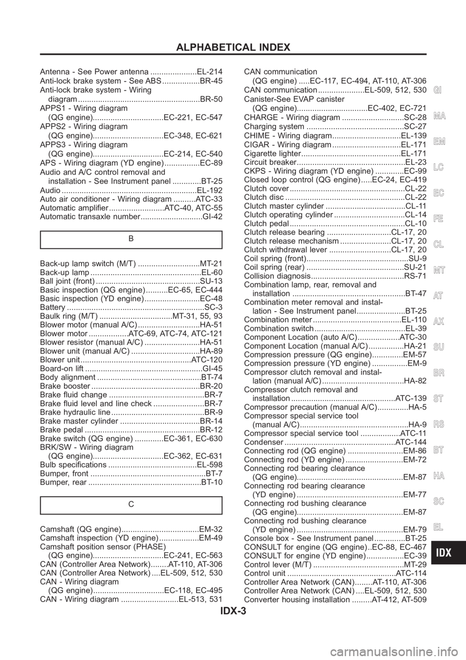
Antenna - See Power antenna .....................EL-214
Anti-lock brake system - See ABS .................BR-45
Anti-lock brake system - Wiring
diagram <0011001100110011001100110011001100110011001100110011001100110011001100110011001100110011001100110011001100110011001100110011001100110011001100110011001100110011001100110011001100110011001100110011001100
1100110011001100110025[R-50
APPS1 - Wiring diagram
(QG engine)................................EC-221, EC-547
APPS2 - Wiring diagram
(QG engine)................................EC-348, EC-621
APPS3 - Wiring diagram
(QG engine)................................EC-214, EC-540
APS - Wiring diagram (YD engine) ................EC-89
Audio and A/C control removal and
installation - See Instrument panel .............BT-25
Audio <0011001100110011001100110011001100110011001100110011001100110011001100110011001100110011001100110011001100110011001100110011001100110011001100110011001100110011001100110011001100110011001100110011001100
110011001100110011001100110011[...EL-192
Auto air conditioner - Wiring diagram ..........ATC-33
Automatic amplifier .........................ATC-40, ATC-55
Automatic transaxle number............................GI-42
B
Back-up lamp switch (M/T) ............................MT-21
Back-up lamp <0011001100110011001100110011001100110011001100110011001100110011001100110011001100110011001100110011001100110011001100110011001100110011001100110011001100110011001100110011001100110011001100110011001100
28002f[-60
Ball joint (front) ...............................................SU-13
Basic inspection (QG engine) ..........EC-65, EC-444
Basic inspection (YD engine) .........................EC-48
Battery <0011001100110011001100110011001100110011001100110011001100110011001100110011001100110011001100110011001100110011001100110011001100110011001100110011001100110011001100110011001100110011001100110011001100
1100110011001100110011[......SC-3
Baulk ring (M/T) .................................MT-31, 55, 93
Blower motor (manual A/C) ............................HA-51
Blower motor ..................ATC-69, ATC-74, ATC-121
Blower resistor (manual A/C) .........................HA-51
Blower unit (manual A/C) ...............................HA-89
Blower unit <0011001100110011001100110011001100110011001100110011001100110011001100110011001100110011001100110011001100110011001100110011001100110011001100110011001100110011001100110011001100110011001100110011001100
24>�7�C-120
Board-on lift <0011001100110011001100110011001100110011001100110011001100110011001100110011001100110011001100110011001100110011001100110011001100110011001100110011001100110011001100110011001100110011001100110011001100
11[..GI-45
Body alignment ...............................................BT-74
Brake booster .................................................BR-20
Brake fluid change ...........................................BR-7
Brake fluid level and line check .......................BR-7
Brake hydraulic line ..........................................BR-9
Brake master cylinder ....................................BR-14
Brake pedal <0011001100110011001100110011001100110011001100110011001100110011001100110011001100110011001100110011001100110011001100110011001100110011001100110011001100110011001100110011001100110011001100110011001100
1100110025[R-12
Brake switch (QG engine) .............EC-361, EC-630
BRK/SW - Wiring diagram
(QG engine)................................EC-362, EC-631
Bulb specifications ........................................EL-598
Bumper, front <0011001100110011001100110011001100110011001100110011001100110011001100110011001100110011001100110011001100110011001100110011001100110011001100110011001100110011001100110011001100110011001100110011001100
11[.BT-7
Bumper, rear <0011001100110011001100110011001100110011001100110011001100110011001100110011001100110011001100110011001100110011001100110011001100110011001100110011001100110011001100110011001100110011001100110011001100
110025[T- 1 0
C
Camshaft (QG engine)...................................EM-32
Camshaft inspection (YD engine) ..................EM-49
Camshaft position sensor (PHASE)
(QG engine)................................EC-241, EC-563
CAN (Controller Area Network)........AT-110, AT-306
CAN (Controller Area Network) ....EL-509, 512, 530
CAN - Wiring diagram
(QG engine) ................................EC-118, EC-495
CAN - Wiring diagram ..........................EL-513, 531CAN communication
(QG engine) .....EC-117, EC-494, AT-110, AT-306
CAN communication .....................EL-509, 512, 530
Canister-See EVAP canister
(QG engine)................................EC-402, EC-721
CHARGE - Wiring diagram ............................SC-28
Charging system ............................................SC-27
CHIME - Wiring diagram...............................EL-139
CIGAR - Wiring diagram ...............................EL-171
Cigarette lighter.............................................EL-171
Circuit breaker.................................................EL-23
CKPS - Wiring diagram (YD engine) .............EC-99
Closed loop control (QG engine) .....EC-24, EC-419
Clutch cover <0011001100110011001100110011001100110011001100110011001100110011001100110011001100110011001100110011001100110011001100110011001100110011001100110011001100110011001100110011001100110011001100110011001100
110011[CL-22
Clutch disc <0011001100110011001100110011001100110011001100110011001100110011001100110011001100110011001100110011001100110011001100110011001100110011001100110011001100110011001100110011001100110011001100110011001100
1100110011[.CL-22
Clutch master cylinder ....................................CL-11
Clutch operating cylinder ................................CL-14
Clutch pedal <0011001100110011001100110011001100110011001100110011001100110011001100110011001100110011001100110011001100110011001100110011001100110011001100110011001100110011001100110011001100110011001100110011001100
110011[CL-10
Clutch release bearing .............................CL-17, 20
Clutch release mechanism .......................CL-17, 20
Clutch withdrawal lever ............................CL-17, 20
Coil spring (front)..............................................SU-9
Coil spring (rear) ............................................SU-21
Collision diagnosis..........................................RS-71
Combination lamp, rear, removal and
installation <0011001100110011001100110011001100110011001100110011001100110011001100110011001100110011001100110011001100110011001100110011001100110011001100110011001100110011001100110011001100110011001100110011001100
11[BT-47
Combination meter removal and instal-
lation - See Instrument panel ......................BT-25
Combination meter ........................................EL-110
Combination switch .........................................EL-39
Component Location (auto A/C) ...................ATC-30
Component Location (manual A/C) ................HA-21
Compression pressure (QG engine)..............EM-57
Compression pressure (YD engine) ................EM-9
Compressor clutch removal and instal-
lation (manual A/C) .....................................HA-82
Compressor clutch removal and
installation ...............................................ATC-139
Compressor precaution (manual A/C)..............HA-5
Compressor special service tool
(manual A/C) .................................................HA-9
Compressor special service tool ..................ATC-11
Condenser <0011001100110011001100110011001100110011001100110011001100110011001100110011001100110011001100110011001100110011001100110011001100110011001100110011001100110011001100110011001100110011001100110011001100
24>�7�&�-144
Connecting rod (QG engine) .........................EM-86
Connecting rod (YD engine) ..........................EM-72
Connecting rod bearing clearance
(QG engine)................................................EM-87
Connecting rod bearing clearance
(YD engine) ................................................EM-77
Connecting rod bushing clearance
(QG engine)................................................EM-87
Connecting rod bushing clearance
(YD engine) ................................................EM-79
Console box - See Instrument panel ..............BT-25
CONSULT for engine (QG engine) ..EC-88, EC-467
CONSULT for engine (YD engine) .................EC-39
Control lever (M/T) .........................................MT-29
Control unit .................................................ATC-114
Controller Area Network (CAN)........AT-110, AT-306
Controller Area Network (CAN) ....EL-509, 512, 530
Converter housing installation .........AT-412, AT-509
GI
MA
EM
LC
EC
FE
CL
MT
AT
AX
SU
BR
ST
RS
BT
HA
SC
EL
ALPHABETICAL INDEX
IDX-3