Page 2760 of 3189
![NISSAN ALMERA N16 2003 Electronic Repair Manual DIAGNOSTIC PROCEDURE 6=NJEL0411S10“SECURITY INDICATOR LAMP DOES NOT LIGHT UP”
1 CHECK FUSE
Check 10A fuse [No. 12, located in the fuse block (J/B)].
Is 10A fuse OK?
Ye s G O T O 2 .
No Replace fus NISSAN ALMERA N16 2003 Electronic Repair Manual DIAGNOSTIC PROCEDURE 6=NJEL0411S10“SECURITY INDICATOR LAMP DOES NOT LIGHT UP”
1 CHECK FUSE
Check 10A fuse [No. 12, located in the fuse block (J/B)].
Is 10A fuse OK?
Ye s G O T O 2 .
No Replace fus](/manual-img/5/57350/w960_57350-2759.png)
DIAGNOSTIC PROCEDURE 6=NJEL0411S10“SECURITY INDICATOR LAMP DOES NOT LIGHT UP”
1 CHECK FUSE
Check 10A fuse [No. 12, located in the fuse block (J/B)].
Is 10A fuse OK?
Ye s G O T O 2 .
No Replace fuse.
2 CHECK SECURITY INDICATOR LAMP
1. Install 10A fuse.
2. Perform initialization with CONSULT-II.
For initialization, refer to “CONSULT-II Operation Manual NATS”.
3. Turn ignition switch OFF.
4. Start engine and turn ignition switch OFF.
5. Check the security indicator lamp lighting.
Security indicator lamp should be light up.
OK or NG
OK INSPECTION END
NG GO TO 3.
3 CHECK SECURITY INDICATOR LAMP POWER SUPPLY CIRCUIT
1. Disconnect combination meter connector.
2. Check voltage between combination meter (security indicator lamp) connector terminal 23 and ground.
YEL809C
OK or NG
OK GO TO 4.
NG Check harness for open or short between fuse and combination meter.
4 CHECK SECURITY INDICATOR LAMP
Check security Indicator Lamp.
Is security indicator lamp OK?
Ye s G O T O 5 .
No Repair or replace combination meter.
NATS (NISSAN ANTI-THEFT SYSTEM)
Trouble Diagnoses/YD Engine Models without Common Rail and K9K Engine Models (Cont’d)
EL-424
Page 2761 of 3189
5 CHECK IMMU FUNCTION
1. Connect IMMU connector.
2. Disconnect combination meter connector.
3. Check continuity between IMMU terminal 6 and ground.
YEL810C
OK or NG
OK Check harness for open or short between security indicator lamp and IMMU.
NG IMMU is malfunctioning.
Replace IMMU.Ref. part No. A
Perform initialization with CONSULT-II.
For initialization, refer to “CONSULT-II operation manual NATS”.
GI
MA
EM
LC
EC
FE
CL
MT
AT
AX
SU
BR
ST
RS
BT
HA
SC
IDX
NATS (NISSAN ANTI-THEFT SYSTEM)
Trouble Diagnoses/YD Engine Models without Common Rail and K9K Engine Models (Cont’d)
EL-425
Page 2762 of 3189
DIAGNOSTIC PROCEDURE 7=NJEL0411S11Self-diagnostic results:
“LOCK MODE” displayed on CONSULT-II screen
1 CONFIRM SELF-DIAGNOSTIC RESULTS
Confirm SELF-DIAGNOSTIC RESULTS “LOCK MODE” is displayed on CONSULT-II screen.
SEL371X
Is CONSULT-II screen displayed as above?
Ye s G O T O 2 .
No GO TO SYMPTOM MATRIX CHART 1.
2 ESCAPE FROM LOCK MODE
1. Turn ignition switch OFF.
2. Turn ignition switch ON with registered key. (Do not start engine.) Wait5 seconds.
3. Return the key to OFF position.
4. Repeat steps 2 and 3 twice (total of three cycles).
5. Start the engine.
Does engine start?
Yes System is OK.
(Now system is escaped from “LOCK MODE”.)
No GO TO 3.
3 CHECK IMMU ILLUSTRATION
Check IMMU installation. Refer to “How to Replace IMMU” in EL-429.
OK or NG
OK GO TO 4.
NG Reinstall IMMU correctly.
NATS (NISSAN ANTI-THEFT SYSTEM)
Trouble Diagnoses/YD Engine Models without Common Rail and K9K Engine Models (Cont’d)
EL-426
Page 2763 of 3189

4 PERFORM INITIALIZATION WITH CONSULT-II
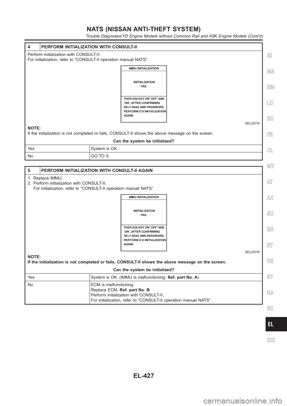
Perform initialization with CONSULT-II.
For initialization, refer to “CONSULT-II operation manual NATS”.
SEL297W
NOTE:
If the initialization is not completed or fails, CONSULT-II shows the above message on the screen.
Can the system be initialized?
Yes System is OK.
No GO TO 5.
5 PERFORM INITIALIZATION WITH CONSULT-II AGAIN
1. Replace IMMU.
2. Perform initialization with CONSULT-II.
For initialization, refer to “CONSULT-II operation manual NATS”.
SEL297W
NOTE:
If the initialization is not completed or fails, CONSULT-II shows the above message on the screen.
Can the system be initialized?
Yes System is OK. (IMMU is malfunctioning.Ref. part No. A)
No ECM is malfunctioning.
Replace ECM.Ref. part No. B
Perform initialization with CONSULT-II.
For initialization, refer to “CONSULT-II operation manual NATS”.
GI
MA
EM
LC
EC
FE
CL
MT
AT
AX
SU
BR
ST
RS
BT
HA
SC
IDX
NATS (NISSAN ANTI-THEFT SYSTEM)
Trouble Diagnoses/YD Engine Models without Common Rail and K9K Engine Models (Cont’d)
EL-427
Page 2764 of 3189
DIAGNOSTIC PROCEDURE 8=NJEL0411S14
1 CHECK HARNESS CONNECTOR CONNECTION
Perform initialization with CONSULT-II.
Check harness connector connection between M31 and M102.
Then initialize NATS. For the initialization operation, refer to “CONSULT-II operation NATS”.
Does the security indicator blink just after initialization?
Yes System is OK. (The malfunction is caused by improper connector connection.)
No GO TO 2.
2 CHECK GROUND CIRCUIT FOR DONGLE UNIT
Check continuity between dongle unit terminal 1 and ground.
SEL029X
YesorNo
Ye s G O T O 3 .
No Repair harness.
3 CHECK INTERFACE CIRCUIT
SEL030X
YesorNo
Ye sDongle unit is malfunctioning.
1. Replace dongle unit.
2. Perform initialization with CONSULT-II. For the initialization procedure, refer to “CON-
SULT-II Operation Manual NATS”.
No Repair harness.
NATS (NISSAN ANTI-THEFT SYSTEM)
Trouble Diagnoses/YD Engine Models without Common Rail and K9K Engine Models (Cont’d)
EL-428
Page 2765 of 3189
SEL096WC
How to Replace NATS IMMUNJEL0412NOTE:
If NATS IMMU is not installed correctly, NATS system will
not operate properly and SELF-DIAG RESULTS on CON-
SULT-II screen will show “LOCK MODE”.GI
MA
EM
LC
EC
FE
CL
MT
AT
AX
SU
BR
ST
RS
BT
HA
SC
IDX
NATS (NISSAN ANTI-THEFT SYSTEM)
How to Replace NATS IMMU
EL-429
Page 2776 of 3189

SKIA1400E
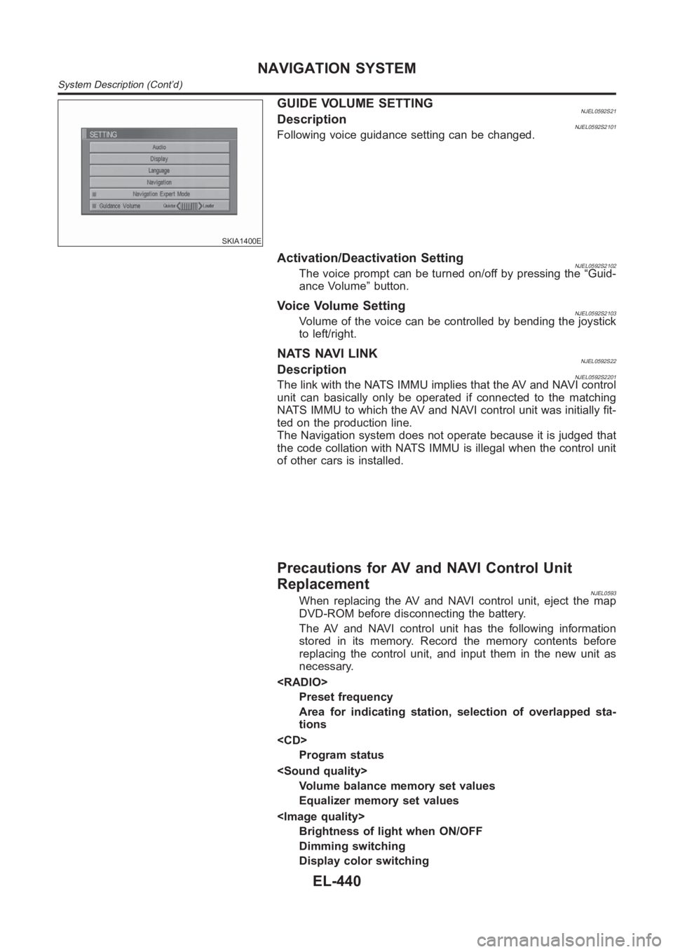
GUIDE VOLUME SETTINGNJEL0592S21DescriptionNJEL0592S2101Following voice guidance setting can be changed.
Activation/Deactivation SettingNJEL0592S2102The voice prompt can be turned on/off by pressing the “Guid-
ance Volume” button.
Voice Volume SettingNJEL0592S2103Volume of the voice can be controlled by bending the joystick
to left/right.
NATS NAVI LINKNJEL0592S22DescriptionNJEL0592S2201The link with the NATS IMMU implies that the AV and NAVI control
unit can basically only be operated if connected to the matching
NATS IMMU to which the AV and NAVI control unit was initially fit-
ted on the production line.
The Navigation system does not operate because it is judged that
the code collation with NATS IMMU is illegal when the control unit
of other cars is installed.
Precautions for AV and NAVI Control Unit
Replacement
NJEL0593When replacing the AV and NAVI control unit, eject the map
DVD-ROM before disconnecting the battery.
The AV and NAVI control unit has the following information
stored in its memory. Record the memory contents before
replacing the control unit, and input them in the new unit as
necessary.
Preset frequency
Area for indicating station, selection of overlapped sta-
tions
Program status
Volume balance memory set values
Equalizer memory set values
Brightness of light when ON/OFF
Dimming switching
Display color switching
NAVIGATION SYSTEM
System Description (Cont’d)
EL-440
Page 2935 of 3189

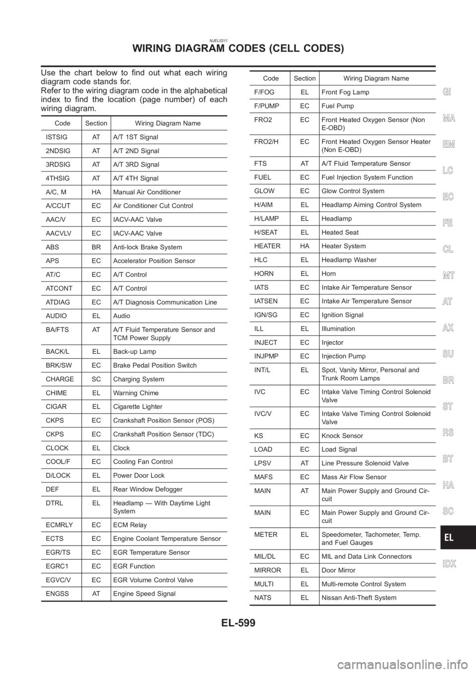
NJEL0311
Use the chart below to find out what each wiring
diagram code stands for.
Refer to the wiring diagram code in the alphabetical
index to find the location (page number) of each
wiring diagram.
Code Section Wiring Diagram Name
ISTSIG AT A/T 1ST Signal
2NDSIG AT A/T 2ND Signal
3RDSIG AT A/T 3RD Signal
4THSIG AT A/T 4TH Signal
A/C, M HA Manual Air Conditioner
A/CCUT EC Air Conditioner Cut Control
AAC/V EC IACV-AAC Valve
AACVLV EC IACV-AAC Valve
ABS BR Anti-lock Brake System
APS EC Accelerator Position Sensor
AT/C EC A/T Control
ATCONT EC A/T Control
ATDIAG EC A/T Diagnosis Communication Line
AUDIO EL Audio
BA/FTS AT A/T Fluid Temperature Sensor and
TCM Power Supply
BACK/L EL Back-up Lamp
BRK/SW EC Brake Pedal Position Switch
CHARGE SC Charging System
CHIME EL Warning Chime
CIGAR EL Cigarette Lighter
CKPS EC Crankshaft Position Sensor (POS)
CKPS EC Crankshaft Position Sensor (TDC)
CLOCK EL Clock
COOL/F EC Cooling Fan Control
D/LOCK EL Power Door Lock
DEF EL Rear Window Defogger
DTRL EL Headlamp — With Daytime Light
System
ECMRLY EC ECM Relay
ECTS EC Engine Coolant Temperature Sensor
EGR/TS EC EGR Temperature Sensor
EGRC1 EC EGR Function
EGVC/V EC EGR Volume Control Valve
ENGSS AT Engine Speed Signal
Code Section Wiring Diagram Name
F/FOG EL Front Fog Lamp
F/PUMP EC Fuel Pump
FRO2 EC Front Heated Oxygen Sensor (Non
E-OBD)
FRO2/H EC Front Heated Oxygen Sensor Heater
(Non E-OBD)
FTS AT A/T Fluid Temperature Sensor
FUEL EC Fuel Injection System Function
GLOW EC Glow Control System
H/AIM EL Headlamp Aiming Control System
H/LAMP EL Headlamp
H/SEAT EL Heated Seat
HEATER HA Heater System
HLC EL Headlamp Washer
HORN EL Horn
IATS EC Intake Air Temperature Sensor
IATSEN EC Intake Air Temperature Sensor
IGN/SG EC Ignition Signal
ILL EL Illumination
INJECT EC Injector
INJPMP EC Injection Pump
INT/L EL Spot, Vanity Mirror, Personal and
Trunk Room Lamps
IVC EC Intake Valve Timing Control Solenoid
Valve
IVC/V EC Intake Valve Timing Control Solenoid
Valve
KS EC Knock Sensor
LOAD EC Load Signal
LPSV AT Line Pressure Solenoid Valve
MAFS EC Mass Air Flow Sensor
MAIN AT Main Power Supply and Ground Cir-
cuit
MAIN EC Main Power Supply and Ground Cir-
cuit
METER EL Speedometer, Tachometer, Temp.
and Fuel Gauges
MIL/DL EC MIL and Data Link Connectors
MIRROR EL Door Mirror
MULTI EL Multi-remote Control System
NATS EL Nissan Anti-Theft System
GI
MA
EM
LC
EC
FE
CL
MT
AT
AX
SU
BR
ST
RS
BT
HA
SC
IDX
WIRING DIAGRAM CODES (CELL CODES)
EL-599