2003 NISSAN 350Z warning
[x] Cancel search: warningPage 32 of 227
IFor a front facing child restraint,
check to make sure the shoulder belt
does not go in front of the child's face
or neck. If it does, put the shoulder
belt behind the child restraint. If you
must install a front facing child re-
straint in the front seat, see instruc-
tions later in this section.
IWhen your child restraint is not in
use, keep it secured with a seat belt
to prevent it from being thrown
around in case of a sudden stop or
accident.
CAUTION
Remember that a child restraint left in a
closed vehicle can become very hot.
Check the seating surface and buckles
before placing your child in the child
restraint.
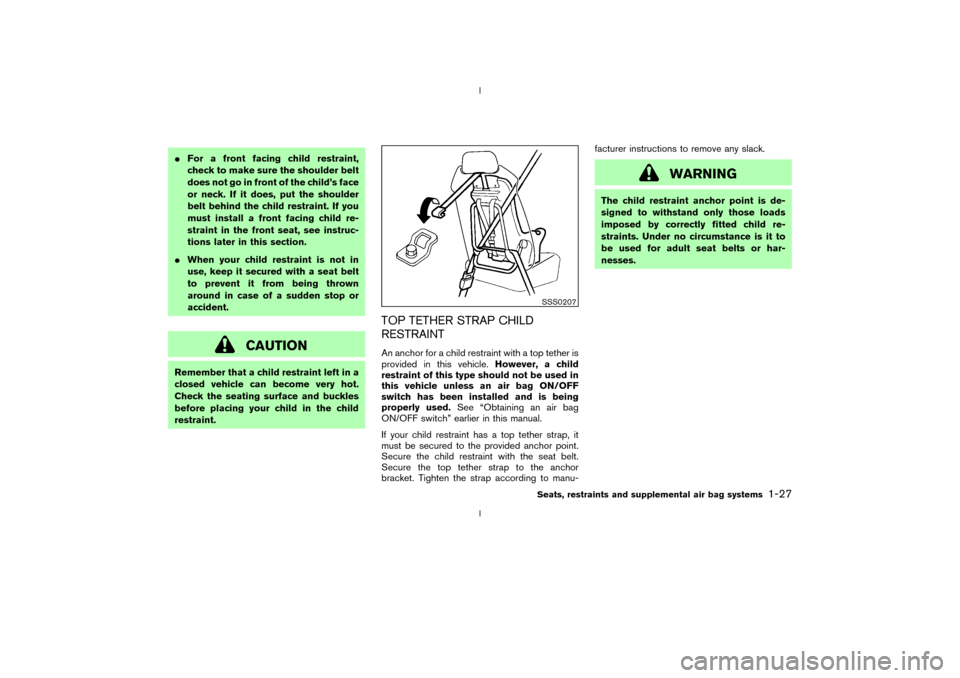
TOP TETHER STRAP CHILD
RESTRAINTAn anchor for a child restraint with a top tether is
provided in this vehicle.However, a child
restraint of this type should not be used in
this vehicle unless an air bag ON/OFF
switch has been installed and is being
properly used.See ªObtaining an air bag
ON/OFF switchº earlier in this manual.
If your child restraint has a top tether strap, it
must be secured to the provided anchor point.
Secure the child restraint with the seat belt.
Secure the top tether strap to the anchor
bracket. Tighten the strap according to manu-facturer instructions to remove any slack.
WARNING
The child restraint anchor point is de-
signed to withstand only those loads
imposed by correctly fitted child re-
straints. Under no circumstance is it to
be used for adult seat belts or har-
nesses.
SSS0207Seats, restraints and supplemental air bag systems
1-27
Z
02.9.13/Z33-D/V5.0
X
Page 33 of 227
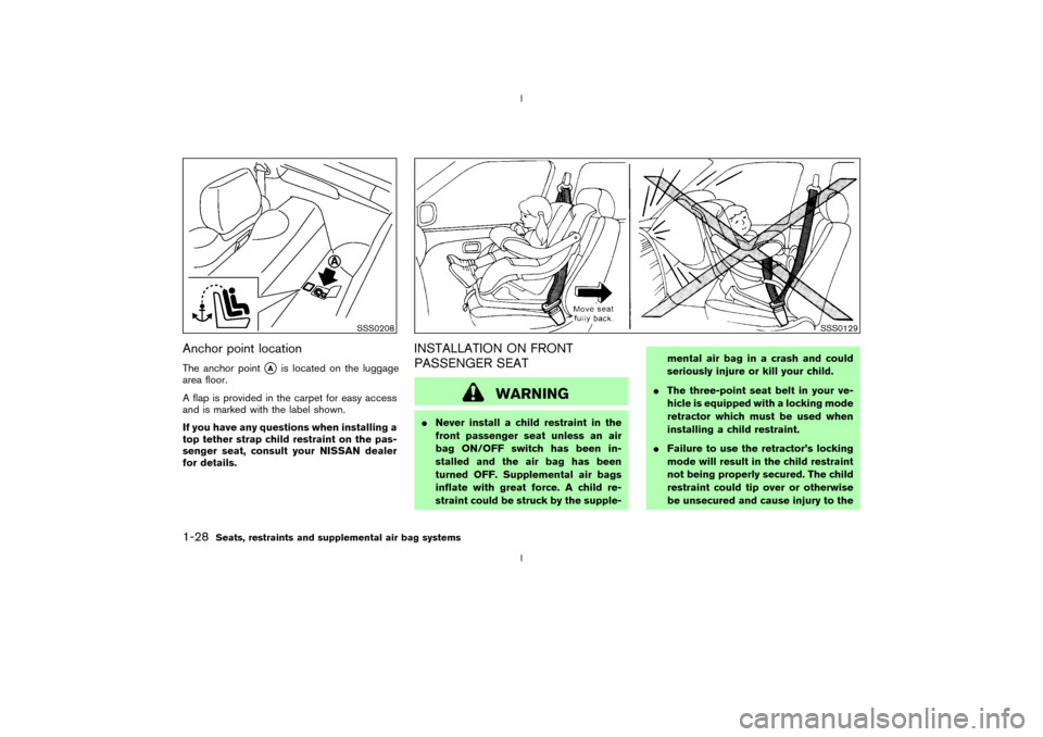
Anchor point locationThe anchor point
qA
is located on the luggage
area floor.
A flap is provided in the carpet for easy access
and is marked with the label shown.
If you have any questions when installing a
top tether strap child restraint on the pas-
senger seat, consult your NISSAN dealer
for details.
INSTALLATION ON FRONT
PASSENGER SEAT
WARNING
INever install a child restraint in the
front passenger seat unless an air
bag ON/OFF switch has been in-
stalled and the air bag has been
turned OFF. Supplemental air bags
inflate with great force. A child re-
straint could be struck by the supple-mental air bag in a crash and could
seriously injure or kill your child.
IThe three-point seat belt in your ve-
hicle is equipped with a locking mode
retractor which must be used when
installing a child restraint.
IFailure to use the retractor's locking
mode will result in the child restraint
not being properly secured. The child
restraint could tip over or otherwise
be unsecured and cause injury to the
SSS0208
SSS0129
1-28
Seats, restraints and supplemental air bag systems
Z
02.9.13/Z33-D/V5.0
X
Page 39 of 227

2 Instruments and controlsInstrument panel ..................................................................... 2-2
Meters and gauges ............................................................... 2-3
Speedometer and odometer ......................................... 2-4
Tachometer ........................................................................ 2-5
Engine coolant temperature gauge ............................. 2-5
Fuel gauge ......................................................................... 2-6
Engine oil pressure gauge ............................................. 2-6
Volt meter ......................................................................... 2-7
Trip computer .................................................................. 2-8
Warning/indicator lights and audible reminders ......... 2-11
Checking bulbs .............................................................. 2-11
Warning lights ................................................................ 2-11
Indicator lights ................................................................ 2-14
Audible reminders.......................................................... 2-16
Security systems.................................................................. 2-16
Vehicle security system................................................ 2-17
Nissan Vehicle Immobilizer System (NVIS) ............ 2-18
Windshield wiper and washer switch ............................ 2-19
Rear window wiper and washer switch ........................ 2-20
Rear window and outside mirror (if so equipped)
defroster switch ................................................................... 2-21
Headlight and turn signal switch..................................... 2-21
Xenon headlights (if so equipped) ............................ 2-21
Headlight switch ............................................................ 2-22Turn signal switch ......................................................... 2-23
Instrument brightness control ..................................... 2-23
Daytime running light system (Canada only) .......... 2-23
Hazard warning flasher switch ......................................... 2-24
Horn ........................................................................................ 2-24
Heated seats (if so equipped) ......................................... 2-25
Vehicle dynamic control (VDC) off switch
(if so equipped).................................................................... 2-26
Traction control system (TCS) off switch
(if so equipped).................................................................... 2-26
Clock ...................................................................................... 2-27
Adjusting the time ......................................................... 2-27
Power outlet.......................................................................... 2-27
Cigarette lighter and ashtray (accessory) .................... 2-28
Storage ................................................................................. 2-29
Instrument pocket (Except for Navigation system
equipped models) ........................................................ 2-29
Sunglasses holder ......................................................... 2-29
Tray.................................................................................... 2-30
Cup holders .................................................................... 2-30
Console box .................................................................... 2-31
Rear floor box ................................................................. 2-32
Rear parcel box .............................................................. 2-32
Windows................................................................................ 2-33
Z
02.9.13/Z33-D/V5.0
X
Page 41 of 227
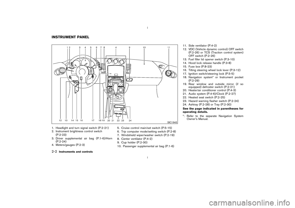
1. Headlight and turn signal switch (P.2-21)
2. Instrument brightness control switch
(P.2-23)
3. Driver supplemental air bag (P.1-6)/Horn
(P.2-24)
4. Meters/gauges (P.2-3)5. Cruise control main/set switch (P.5-15)
6. Trip computer mode/setting switch (P.2-8)
7. Windshield wiper/washer switch (P.2-19)
8. Center ventilator (P.4-2)
9. Cup holder (P.2-30)
10. Passenger supplemental air bag (P.1-6)11. Side ventilator (P.4-2)
12. VDC (Vehicle dynamic control) OFF switch
(P.2-26) or TCS (Traction control system)
OFF switch (P.2-26)
13. Fuel filler lid opener switch (P.3-10)
14. Hood lock release handle (P.3-8)
15. Fuse box (P.8-23)
16. Tilting steering wheel lock lever (P.3-12)
17. Ignition switch/steering lock (P.5-5)
18. Navigation system* or Instrument pocket
(P.2-29)
19. Rear window and outside mirror (if so
equipped) defroster switch (P.2-21)
20. Heater/air conditioner control (P.4-3)
21. Audio system (P.4-6)/Clock (P.2-27)
22. Heated seat switch (P.2-25)
23. Hazard warning flasher switch (P.2-24)
24. Ashtray (P.2-28) or Tray (P.2-30)
See the page indicated in parentheses for
operating details.
*: Refer to the separate Navigation System
Owner's Manual.
SIC1943
INSTRUMENT PANEL2-2
Instruments and controls
Z
02.9.13/Z33-D/V5.0
X
Page 42 of 227
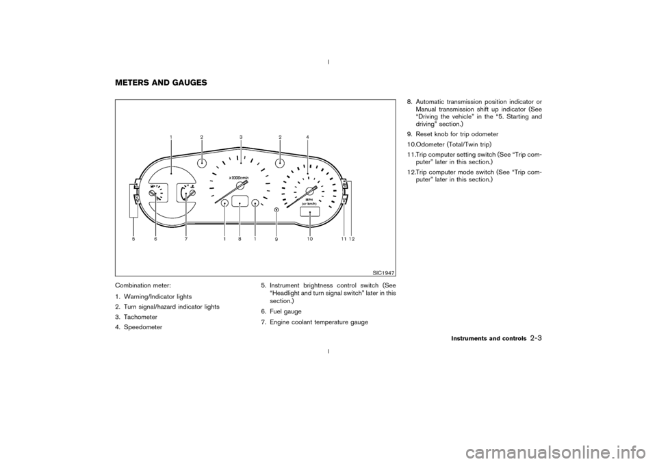
Combination meter:
1. Warning/Indicator lights
2. Turn signal/hazard indicator lights
3. Tachometer
4. Speedometer5. Instrument brightness control switch (See
ªHeadlight and turn signal switchº later in this
section.)
6. Fuel gauge
7. Engine coolant temperature gauge8. Automatic transmission position indicator or
Manual transmission shift up indicator (See
ªDriving the vehicleº in the ª5. Starting and
drivingº section.)
9. Reset knob for trip odometer
10.Odometer (Total/Twin trip)
11.Trip computer setting switch (See ªTrip com-
puterº later in this section.)
12.Trip computer mode switch (See ªTrip com-
puterº later in this section.)
SIC1947
METERS AND GAUGES
Instruments and controls
2-3
Z
02.9.13/Z33-D/V5.0
X
Page 45 of 227
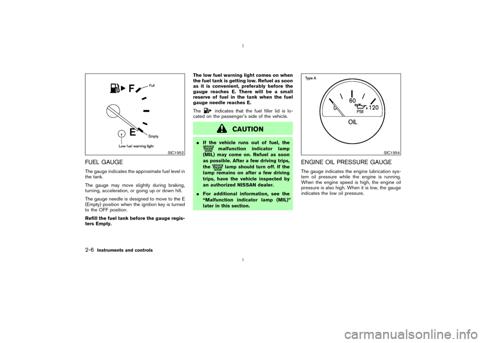
FUEL GAUGEThe gauge indicates the approximate fuel level in
the tank.
The gauge may move slightly during braking,
turning, acceleration, or going up or down hill.
The gauge needle is designed to move to the E
(Empty) position when the ignition key is turned
to the OFF position.
Refill the fuel tank before the gauge regis-
ters Empty.The low fuel warning light comes on when
the fuel tank is getting low. Refuel as soon
as it is convenient, preferably before the
gauge reaches E. There will be a small
reserve of fuel in the tank when the fuel
gauge needle reaches E.
The
indicates that the fuel filler lid is lo-
cated on the passenger's side of the vehicle.
CAUTION
IIf the vehicle runs out of fuel, the
malfunction indicator lamp
(MIL) may come on. Refuel as soon
as possible. After a few driving trips,
the
lamp should turn off. If the
lamp remains on after a few driving
trips, have the vehicle inspected by
an authorized NISSAN dealer.
IFor additional information, see the
ªMalfunction indicator lamp (MIL)º
later in this section.
ENGINE OIL PRESSURE GAUGEThe gauge indicates the engine lubrication sys-
tem oil pressure while the engine is running.
When the engine speed is high, the engine oil
pressure is also high. When it is low, the gauge
indicates the low oil pressure.
SIC1952
SIC1954
2-6
Instruments and controls
Z
02.9.13/Z33-D/V5.0
X
Page 47 of 227
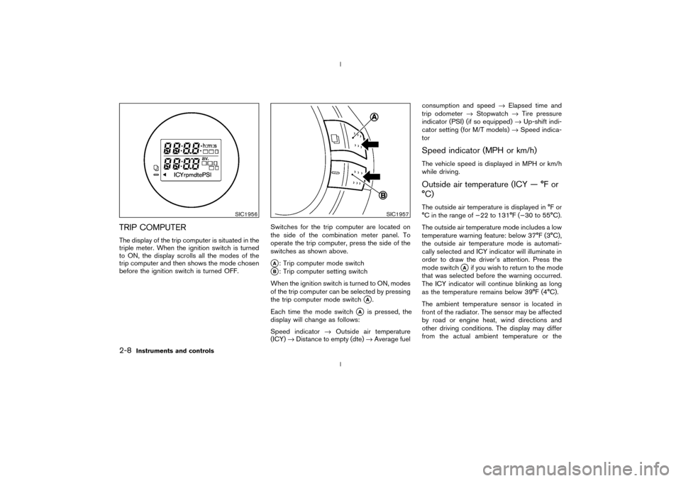
TRIP COMPUTERThe display of the trip computer is situated in the
triple meter. When the ignition switch is turned
to ON, the display scrolls all the modes of the
trip computer and then shows the mode chosen
before the ignition switch is turned OFF.Switches for the trip computer are located on
the side of the combination meter panel. To
operate the trip computer, press the side of the
switches as shown above.
qA: Trip computer mode switch
qB: Trip computer setting switch
When the ignition switch is turned to ON, modes
of the trip computer can be selected by pressing
the trip computer mode switch
qA.
Each time the mode switch
qA
is pressed, the
display will change as follows:
Speed indicator®Outside air temperature
(ICY)®Distance to empty (dte)®Average fuelconsumption and speed®Elapsed time and
trip odometer®Stopwatch®Tire pressure
indicator (PSI) (if so equipped)®Up-shift indi-
cator setting (for M/T models)®Speed indica-
tor
Speed indicator (MPH or km/h)The vehicle speed is displayed in MPH or km/h
while driving.Outside air temperature (ICY Ð ÉF or
ÉC)The outside air temperature is displayed in ÉF or
ÉC in the range of þ22 to 131ÉF (þ30 to 55ÉC).
The outside air temperature mode includes a low
temperature warning feature: below 37ÉF (3ÉC),
the outside air temperature mode is automati-
cally selected and ICY indicator will illuminate in
order to draw the driver's attention. Press the
mode switch
qAif you wish to return to the mode
that was selected before the warning occurred.
The ICY indicator will continue blinking as long
as the temperature remains below 39ÉF (4ÉC).
The ambient temperature sensor is located in
front of the radiator. The sensor may be affected
by road or engine heat, wind directions and
other driving conditions. The display may differ
from the actual ambient temperature or the
SIC1956
SIC1957
2-8
Instruments and controls
Z
02.9.13/Z33-D/V5.0
X
Page 48 of 227

temperature displayed on various signs or bill-
boards.Distance to empty (dte Ð mile or km)The distance to empty (dte) mode provides you
with an estimation of the distance that can be
driven before refueling. The dte is constantly
being calculated, based on the amount of fuel in
the fuel tank and the actual fuel consumption.
The display is updated every 30 seconds.
The dte mode includes a low range warning
feature: when the fuel level is low, the dte mode
is automatically selected and the digits blink in
order to draw the driver's attention. Press the
mode switch
qAif you wish to return to the mode
that was selected before the warning occurred.
The dte indicator will remain blinking until the
vehicle is refuelled.
When the fuel level drops even lower, the dte
display will change to (----).
NOTE:
IIf the amount of fuel added while the
ignition switch is OFF is small, the dis-
play just before the ignition switch is
turned OFF may continue to be dis-
played.
IWhen driving uphill or rounding curves,
the fuel in the tank shifts, which maymomentarily change the display.
Average fuel consumption
(Mpg or l/100 km)The average fuel consumption mode shows the
average fuel consumption since the last reset.
Resetting is done by pressing the trip computer
setting switch
qB
for more than approximately 1
second. (The average speed is also reset at the
same time.)
The display is updated every 30 seconds. At
about the first 1/3 miles (500 m) after a reset,
the display shows (----).
Average speed (MPH or km/h)The average speed mode shows the average
vehicle speed since the last reset. Resetting is
done by pressing the setting switch
qB
for more
than approximately 1 second. (The average fuel
consumption is also reset at the same time.)
The display is updated every 30 seconds. The
first 30 seconds after a reset, the display shows
(----).
Elapsed time (h:m:s)The elapsed time mode shows the time since the
last reset. The displayed time can be reset by
pressing the trip computer setting switch
qB
for
more than approximately 1 second. (The tripodometer is also reset at the same time.)
Trip odometer (MLS or km)The trip odometer mode shows the total dis-
tance the vehicle has been driven since the last
reset. Resetting is done by pressing the setting
switch
qBfor more than approximately 1 second.
(The elapsed time is also reset at the same time.)
Stopwatch (h:m:s)You can use the trip computer as a stopwatch.
Each time the trip computer setting switch
qB
is
pressed, the stopwatch will be operated as
follows:
After 100 hours, the time will start from the reset
display again.
Even if the display is switched to the other mode
while the time is starting, the stopwatch contin-
ues to advance until you stop the time in the
stopwatch mode. When the ignition switch is
turned OFF, the time is reset.Tire pressure indicator (PSI) (if so
equipped)The tire pressure indicator shows tire pressure
(0 - 51 psi) of all wheels (except the spare tire)
Instruments and controls
2-9
Z
02.9.13/Z33-D/V5.0
X