2003 NISSAN 350Z sensor
[x] Cancel search: sensorPage 16 of 227
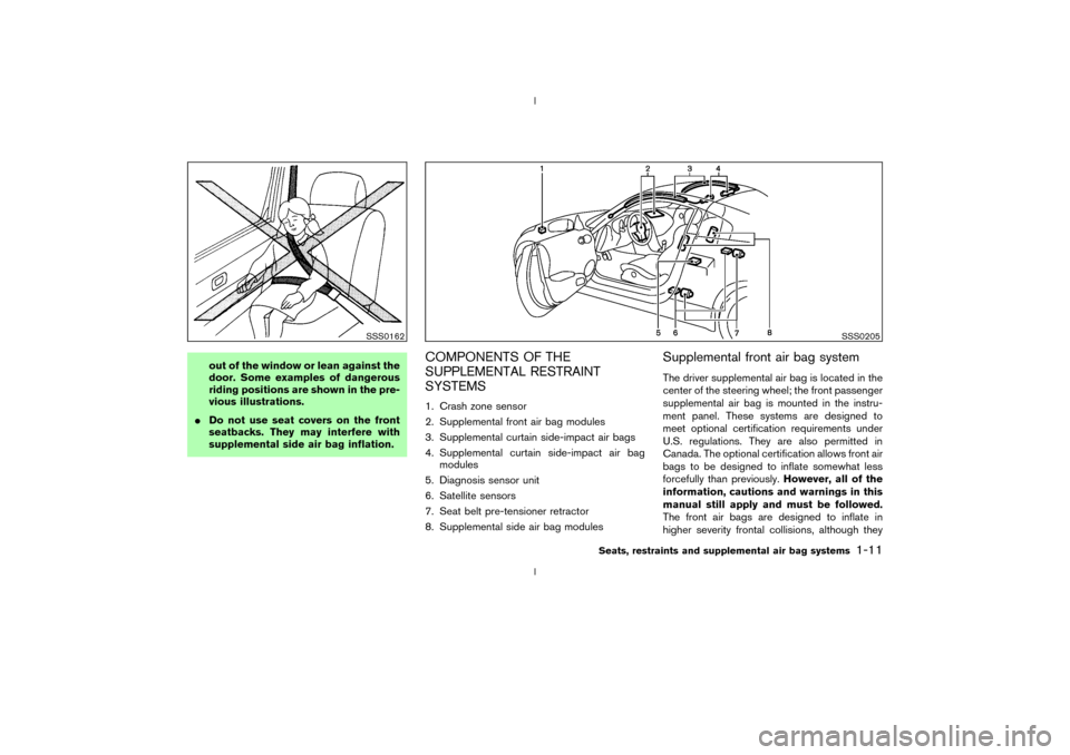
out of the window or lean against the
door. Some examples of dangerous
riding positions are shown in the pre-
vious illustrations.
IDo not use seat covers on the front
seatbacks. They may interfere with
supplemental side air bag inflation.
COMPONENTS OF THE
SUPPLEMENTAL RESTRAINT
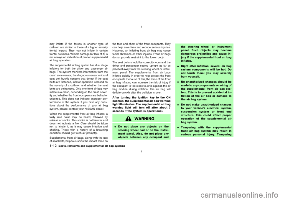
SYSTEMS1. Crash zone sensor
2. Supplemental front air bag modules
3. Supplemental curtain side-impact air bags
4. Supplemental curtain side-impact air bag
modules
5. Diagnosis sensor unit
6. Satellite sensors
7. Seat belt pre-tensioner retractor
8. Supplemental side air bag modules
Supplemental front air bag systemThe driver supplemental air bag is located in the
center of the steering wheel; the front passenger
supplemental air bag is mounted in the instru-
ment panel. These systems are designed to
meet optional certification requirements under
U.S. regulations. They are also permitted in
Canada. The optional certification allows front air
bags to be designed to inflate somewhat less
forcefully than previously.However, all of the
information, cautions and warnings in this
manual still apply and must be followed.
The front air bags are designed to inflate in
higher severity frontal collisions, although they
SSS0162
SSS0205
Seats, restraints and supplemental air bag systems
1-11
Z
02.9.13/Z33-D/V5.0
X
Page 17 of 227
may inflate if the forces in another type of
collision are similar to those of a higher severity
frontal impact. They may not inflate in certain
frontal collisions. Vehicle damage (or lack of it) is
not always an indication of proper supplemental
air bag operation.
The supplemental air bag system has dual stage
inflators for both the driver and passenger air
bags. The system monitors information from the
crash zone sensor, the diagnosis sensor unit and
seat belt buckle sensors that detect if the seat
belts are fastened, inflator operation is based on
the severity of a collision and whether the seat
belts are being used. Only one front air bag may
inflate in a crash, depending on the crash sever-
ity and whether the front occupants are belted or
unbelted. This does not indicate improper per-
formance of the system. If you have any ques-
tions about the performance of your air bag
system, please contact your NISSAN dealer.
When the supplemental front air bag inflates, a
fairly loud noise may be heard, followed by
release of smoke. This smoke is not harmful and
does not indicate a fire. Care should be taken
not to inhale it, as it may cause irritation and
choking. Those with a history of a breathing
condition should get fresh air promptly.
Supplemental front air bags, along with the use
of seat belts, help to cushion the impact force onthe face and chest of the front occupants. They
can help save lives and reduce serious injuries.
However, an inflating front air bag may cause
facial abrasions or other injuries. Front air bags
do not provide restraint to the lower body.
The seat belts should be correctly worn and the
driver and passenger seated upright as far as
practical away from the steering wheel or instru-
ment panel. The supplemental front air bags
inflates quickly in order to help protect the front
occupants. Because of this, the force of the front
air bag inflating can increase the risk of injury if
the occupant is too close to, or is against, the air
bag module during inflation. The air bag will
deflate quickly after the collision is over.
After turning the ignition key to the ON
position, the supplemental air bag warning
light illuminates. The supplemental air bag
warning light will turn off after about 7
seconds if the system is operational.
WARNING
IDo not place any objects on the
steering wheel pad or on the instru-
ment panel. Also, do not place any
objects between any occupant andthe steering wheel or instrument
panel. Such objects may become
dangerous projectiles and cause in-
jury if the supplemental front air bag
inflates.
IRight after inflation, several air bag
system components will be hot. Do
not touch them; you may severely
burn yourself.
INo unauthorized changes should be
made to any components or wiring of
the supplemental front air bag sys-
tem. This is to prevent accidental in-
flation of the air bag or damage to
the air bag system.
IDo not make unauthorized changes
to your vehicle's electrical system,
suspension system or front end
structure. This could affect proper
operation of the supplemental air
bag system.
ITampering with the supplemental
front air bag system may result in
serious personal injury. Tampering
1-12
Seats, restraints and supplemental air bag systems
Z
02.9.13/Z33-D/V5.0
X
Page 22 of 227
SUPPLEMENTAL AIR BAG
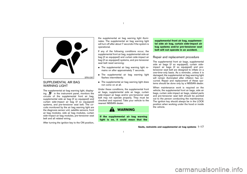
WARNING LIGHTThe supplemental air bag warning light, display-
ing
in the instrument panel, monitors the
circuits of the supplemental front air bag,
supplemental side air bag (if so equipped) and
curtain side-impact air bag (if so equipped)
systems, and pre-tensioner seat belt. The cir-
cuits monitored by the air bag warning light are
the diagnosis sensor unit, satellite sensors, front
air bag modules, side air bag modules, curtain
side-impact air bag modules, pre-tensioner seat
belt and all related wiring.
After turning the ignition key to the ON position,the supplemental air bag warning light illumi-
nates. The supplemental air bag warning light
will turn off after about 7 seconds if the system is
operational.
If any of the following conditions occur, the
supplemental front air bag, supplemental side air
bag (if so equipped) and curtain side-impact air
bag (if so equipped) systems, and pre-tensioner
seat belt need servicing:
IThe supplemental air bag warning light re-
mains on after approximately 7 seconds.
IThe supplemental air bag warning light
flashes intermittently.
IThe supplemental air bag warning light does
not come on at all.
Under these conditions, the supplemental front
air bags, supplemental side air bags, curtain
side-impact air bags and/or pre-tensioner seat
belt may not operate properly. They must be
checked and repaired. Take your vehicle to the
nearest NISSAN dealer.
WARNING
If the supplemental air bag warning
light is on, it could mean that thesupplemental front air bag, supplemen-
tal side air bag, curtain side-impact air
bag systems and/or pre-tensioner seat
belt will not operate in an accident.
Repair and replacement procedureThe supplemental front air bags, supplemental
side air bags (if so equipped), curtain side-
impact air bags (if so equipped) and pre-
tensioner seat belt are designed to inflate on a
one-time-only basis. As a reminder, unless it is
damaged, the supplemental air bag warning light
will remain illuminated after inflation has oc-
curred. Repair and replacement of these sys-
tems should be done only by a NISSAN dealer.
When maintenance work is required on the
vehicle, the supplemental front air bags, side air
bags, curtain side-impact air bags, related parts
and pre-tensioner seat belt should be pointed
out to the person conducting the maintenance.
The ignition key should always be in the LOCK
position when working under the hood or inside
the vehicle.
SPA1097
Seats, restraints and supplemental air bag systems
1-17
Z
02.9.13/Z33-D/V5.0
X
Page 47 of 227

TRIP COMPUTERThe display of the trip computer is situated in the
triple meter. When the ignition switch is turned
to ON, the display scrolls all the modes of the
trip computer and then shows the mode chosen
before the ignition switch is turned OFF.Switches for the trip computer are located on
the side of the combination meter panel. To
operate the trip computer, press the side of the
switches as shown above.
qA: Trip computer mode switch
qB: Trip computer setting switch
When the ignition switch is turned to ON, modes
of the trip computer can be selected by pressing
the trip computer mode switch
qA.
Each time the mode switch
qA
is pressed, the
display will change as follows:
Speed indicator®Outside air temperature
(ICY)®Distance to empty (dte)®Average fuelconsumption and speed®Elapsed time and
trip odometer®Stopwatch®Tire pressure
indicator (PSI) (if so equipped)®Up-shift indi-
cator setting (for M/T models)®Speed indica-
tor
Speed indicator (MPH or km/h)The vehicle speed is displayed in MPH or km/h
while driving.Outside air temperature (ICY Ð ÉF or
ÉC)The outside air temperature is displayed in ÉF or
ÉC in the range of þ22 to 131ÉF (þ30 to 55ÉC).
The outside air temperature mode includes a low
temperature warning feature: below 37ÉF (3ÉC),
the outside air temperature mode is automati-
cally selected and ICY indicator will illuminate in
order to draw the driver's attention. Press the
mode switch
qAif you wish to return to the mode
that was selected before the warning occurred.
The ICY indicator will continue blinking as long
as the temperature remains below 39ÉF (4ÉC).
The ambient temperature sensor is located in
front of the radiator. The sensor may be affected
by road or engine heat, wind directions and
other driving conditions. The display may differ
from the actual ambient temperature or the
SIC1956
SIC1957
2-8
Instruments and controls
Z
02.9.13/Z33-D/V5.0
X
Page 49 of 227
by sending a signal from a sensor that is installed
in each wheel. Press the trip computer setting
switch
qBto change the display to F (front) or R
(rear).
The tire pressure sensor will activate only when
the vehicle is driven at speeds above 20 MPH
(32 km/h). If the tire pressure signal cannot be
received correctly, the display shows (----).
The tire pressure indicator mode includes a low
tire pressure warning feature. If the vehicle is
being driven with very low tire pressure or a flat
tire, the tire pressure indicator mode is automati-
cally selected and the PSI indicator will blink in
order to attract the driver's attention. Press the
trip computer mode switch
qA
if you wish to
return to the mode that was selected before the
warning occurred. The PSI indicator will con-
tinue blinking until the tire pressure of each tire is
properly adjusted.
For additional information, see ªLow tire pres-
sure warning systemº in the ª5. Starting and
drivingº section and ªFlat tireº in the ª6. In case
of emergencyº section.
Tire pressure shown in the display may rise
or fall while driving depending on the driv-
ing conditions (heat, etc.) and/or the out-
side temperature. This does not indicate a
system malfunction.
WARNING
The low tire pressure warning system is
not a substitute for the regular tire pres-
sure check. Be sure to check the tire
pressure regularly and adjust it to the
COLD tire pressure shown in the tire
placard.Up-shift indicator setting (rpm) (for
manual transmission models)The up-shift indicator setting mode is used to
set the desired engine speed (rpm) for the
up-shift indicator (situated in the tachometer) to
illuminate. When the engine speed approaches
or reaches the set figure, the up-shift indicator
will flash or illuminate to show the driver the
timing for shifting into a higher gear. See ªDriving
the vehicleº in the ª5. Starting and drivingº
section for the use of the up-shift indicator.
When the up-shift indicator setting mode is
selected, the rpm indicator blinks and the engine
speed currently set is displayed. (The initial
factory setting is 6,600 rpm.) The figure can be
changed between 2,000 and 8,000 rpm by
pressing trip computer setting switch
qB. Press-
ing the switch for less than approximately 1second will add the figure by 100 rpm. If press-
ing for more than approximately 1 second, the
figure will increase by 500 rpm.
If the battery cable is disconnected, the set
engine speed will be returned to the initial figure
(6,600 rpm).
Display priorityIf a low outside air temperature warning,
low dte (distance to empty) range warning
and low tire pressure warning occur simul-
taneously, other display modes switch au-
tomatically to the outside air temperature
display.
When trip computer mode switch
qA
is
pressed, the display switches to the mode
chosen before the warning display, but the
ICY indicator will continue blinking.
2-10
Instruments and controls
Z
02.9.13/Z33-D/V5.0
X
Page 102 of 227

(
and
) will flash twice, and then
the intake air will be controlled automatically.
During this AUTO mode, the indicator light of
the currently selected mode illuminates.
IWhen the air flow control dial is in the
or
position, the air recirculation
mode does not activate.
Air flow controlTurning the air flow control dial selects the air
outlet to:
: Air flows from center and side ventila-
tors.: Air flows from center and side ventila-
tors and foot outlets.: Air flows mainly from foot outlets.: Air flows from defroster and foot out-
lets.: Air flows mainly from defroster outlets.
To turn the system offTurn the fan control dial to the OFF position.OPERATING TIPSWhen the engine coolant temperature and out-
side air temperature are low, the air flow from the
foot outlets may not operate for a maximum of150 seconds. However, this is not a malfunction.
After the coolant temperature warms up, the air
flow from the foot outlets will operate normally.
Sensor
qA
on the instrument panel helps main-
tain a constant temperature; do not put anything
on or around this sensor.
SAA0603
Heater, air conditioner and audio systems
4-5
Z
02.9.13/Z33-D/V5.0
X
Page 120 of 227
d. You have had an accident involv-
ing damage to the exhaust system,
underbody, or rear of the vehicle.
THREE WAY CATALYSTThe three way catalyst is an emission control
device installed in the exhaust system. Exhaust
gases in the converter are burned at high tem-
peratures to help reduce pollutants.
WARNING
IThe exhaust gas and the exhaust sys-
tem are very hot. Keep people, ani-
mals or flammable materials away
from the exhaust system compo-
nents.
IDo not stop or park the vehicle over
flammable materials such as dry
grass, waste paper or rags. They may
ignite and cause a fire.
CAUTION
IDo not use leaded gasoline. Deposits
from leaded gasoline seriously re-
duce the three way catalyst's ability
to help reduce exhaust pollutants.
IKeep your engine tuned up. Malfunc-
tions in the ignition, fuel injection, or
electrical systems can cause overrich
fuel flow into the three way catalyst,
causing it to overheat. Do not keep
driving if the engine misfires, or if
noticeable loss of performance or
other unusual operating conditions
are detected. Have the vehicle in-
spected promptly by a NISSAN
dealer.
IAvoid driving with an extremely low
fuel level. Running out of fuel could
cause the engine to misfire, damag-
ing the three way catalyst.
IDo not race the engine while warm-
ing it up.
IDo not push or tow your vehicle to
start the engine.
LOW TIRE PRESSURE WARNING
SYSTEM (if so equipped)The low tire pressure warning system displays
pressure of all tires (except the spare tire) on the
trip computer by sending a signal from a sensor
that is installed in each wheel.
The low tire pressure warning system will acti-
vate only when the vehicle is driven at speeds
above 20 MPH (32 km/h). Also, this system may
not detect a sudden drop in tire pressure (for
example, a flat tire by catching something while
driving).
Frequently check the tire pressure indicator on
the trip computer and adjust pressure of each
tire properly. See ªTrip computerº in the ª2.
Instruments and controlsº section for the tire
pressure indicator.Flat tire warningIf the vehicle is being driven with a flat tire or
extremely low tire pressure (lower than 28 psi),
the low tire pressure warning light comes on,
and the chime sounds for about 10 seconds. On
the trip computer, the PSI indicator starts flash-
ing and the current display switches to the tire
pressure indicator.
For additional information regarding the above
warning, see ªTrip computerº and
Starting and driving
5-3
Z
02.9.13/Z33-D/V5.0
X
Page 121 of 227
ªWarning/indicator lights and audible remind-
ersº in the ª2. Instruments and controlsº section.
WARNING
IIf the low tire pressure warning light
in the meter panel comes on and/or
the PSI indicator on the trip computer
flashes while driving, avoid sudden
steering maneuvers or abrupt brak-
ing, reduce vehicle speed, pull off the
road to a safe location and stop the
vehicle as soon as possible. Serious
vehicle damage could occur and may
lead to an accident and could result
in serious personal injury. Check the
pressure for all four tires and adjust
the pressure to the COLD tire pres-
sure shown on the tire placard. If you
have a flat tire, replace it with a spare
tire as soon as possible. (See ªFlat
tireº in the ª6. In case of emergencyº
section for changing a flat tire.)
IWhen a spare tire is mounted or a
wheel is replaced, tire pressure will
not be indicated and the low tirepressure warning system will not
function. Contact your NISSAN
dealer as soon as possible for tire
replacement and/or system reset-
ting.
IDo not inject any tire liquid or aerosol
tire sealant into the tires, as this may
cause a malfunction of the tire pres-
sure sensors.
CAUTION
Do not place metalized film or any metal
parts (antenna, etc.) on the windows.
This may cause poor reception of the
signals from the tire pressure sensors,
and the low tire pressure warning sys-
tem will not function properly.
FCC Notice:
Changes or modifications not expressly
approved by the manufacturer compliance
could void the user's authority to operate
the equipment.This device complies with Part 15 of the
FCC Rules and RSS-210 of Industry
Canada.
Operation is subject to the following two
conditions: (1) This device may not cause
harmful interference, and (2) this device
must accept any interference received, in-
cluding interference that may cause undes-
ired operation of the device.
AVOIDING COLLISION AND
ROLLOVER
WARNING
Failure to operate this vehicle in a safe
and prudent manner may result in loss
of control or an accident.
Be alert and drive defensively at all times. Obey
all traffic regulations. Avoid excessive speed,
high speed cornering, or sudden steering ma-
neuvers, because these driving practices could
cause you to lose control of your vehicle.As
with any vehicle, a loss of control could
result in a collision with other vehicles or
objects, or cause the vehicle to rollover,
particularly if the loss of control causes the
vehicle to slide sideways.Be attentive at all
5-4
Starting and driving
Z
02.9.13/Z33-D/V5.0
X