Page 310 of 376

310 Practical hintsFlat tireAfter 5 minutes, the pressure gauge must
display at least 26 psi (1.8 bar). The air
hose can become hot during inflation.
Please exercise appropriate caution.�
If this tire pressure is not attained, turn
off the electric air pump, detach the fill-
er hose from the tire valve, and drive
vehicle back and forth very slowly ap-
proximately 30 ft (10 m).
This serves to better distribute the
TIREFIT sealant material inside the tire.
�
Unscrew the air pump’s air hose5 from
flange6 of the TIREFIT container.
�
Inflate the tire again.
�
After attaining a tire pressure of 26 psi
(1.8 bar), press0 on electric air pump
switch8.
The electric air pump should now be
switched off.
�
Turn the key in the ignition to
position0 (
�page 29).
or
�
Press the KEYLESS-GO* start/stop
button (
�page 30) on the selector le-
ver once. Do not depress brake pedal.
�
Detach the electric air pump.
The air hose may still be hot. Please ex-
ercise appropriate caution.
�
Store the electrical plug and the air
hose behind the flap and place the air
pump back in the trunk.
�
Close the trunk lid.
�
Drive away immediately.
The TIREFIT sealant will distribute itself
evenly inside the tire.
Warning!
G
If a tire pressure of 26 psi (1.8 bar) is not at-
tained, tire is too severely damaged for
TIREFIT to provide a reliable tire repair.
In this case, TIREFIT cannot properly seal
the tire.
Do not drive the vehicle.
Contact the nearest Mercedes-Benz Center
or call Roadside Assistance.
Warning!
G
Do not exceed vehicle speed of
50 mph (80 km / h). A TIREFIT repair is not
designed to operate at higher speeds.
The sticker must be attached on the instru-
ment cluster where it will be easily seen by
the driver.
Vehicle handling characteristics may
change. Adapt your driving accordingly.
Page 314 of 376
314 Practical hintsFlat tire1Jack arm
2Jack support tube hole
3Crank�
Insert jack arm1 fully into the tube
hole2 up to the stop.
�
Keeping jack in this position, turn
crank3 clockwise until the jack base
meets the ground. Make sure the jack
is vertical (plumb line).
�
Continue to turn the crank until the tire
is a maximum of 1.2 in (3 cm) from the
ground.Removing the wheel
1Alignment bolt
�
Unscrew upper-most wheel bolt and re-
move.
�
Replace this wheel bolt with the align-
ment bolt 1 supplied in the tool kit.
�
Remove the remaining bolts.
�
Remove the wheel.
Warning!
G
Insert the jack arm fully into the jack sup-
port tube hole up to the stop. Otherwise the
vehicle may fall from the jack and cause per-
sonal injury or damage to the vehicle.
!Do not place wheel bolts in sand or dirt.
This could result in damage to the bolt
and wheel hub threads.
Page 316 of 376

316 Practical hintsFlat tireInflating the spare tire�
Take the electric air pump out of the
trunk (
�page 289).
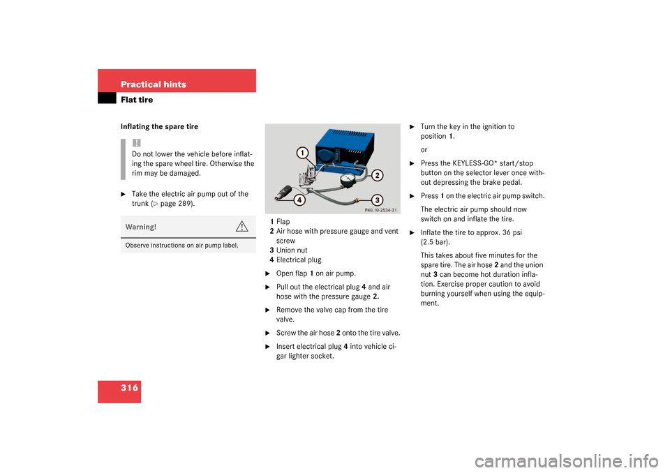
1Flap
2Air hose with pressure gauge and vent
screw
3Union nut
4Electrical plug
�
Open flap 1 on air pump.
�
Pull out the electrical plug 4 and air
hose with the pressure gauge 2.
�
Remove the valve cap from the tire
valve.
�
Screw the air hose 2 onto the tire valve.
�
Insert electrical plug 4 into vehicle ci-
gar lighter socket.
�
Turn the key in the ignition to
position1.
or
�
Press the KEYLESS-GO* start/stop
button on the selector lever once with-
out depressing the brake pedal.
�
Press 1 on the electric air pump switch.
The electric air pump should now
switch on and inflate the tire.
�
Inflate the tire to approx. 36 psi
(2.5 bar).
This takes about five minutes for the
spare tire. The air hose 2 and the union
nut 3 can become hot duration infla-
tion. Exercise proper caution to avoid
burning yourself when using the equip-
ment.
!Do not lower the vehicle before inflat-
ing the spare wheel tire. Otherwise the
rim may be damaged.Warning!
G
Observe instructions on air pump label.
Page 317 of 376

317 Practical hints
Flat tire
�
Press 0 on the electric air pump switch.
�
Turn the key in the ignition to
position0.
or
�
Press KEYLESS-GO* start/stop button
on the selector lever twice without de-
pressing the brake pedal.
The electric air pump should now be
switched off.
�
If the tire pressure is above 36 psi
(2.5 bar), release excess tire pressure
using the vent screw.
�
Detach the electric air pump.
�
Stow the electrical plug and the air
hose behind the flap and place the air
pump back in the trunk.
!Do not operate the air pump longer
than eight minutes without interrup-
tion. Otherwise it may overheat.
You may operate the air pump again af-
ter it has cooled off.
Warning!
G
Follow recommend inflation pressures.
Do not overinflate tires. Overinflating tires
can result in sudden deflation (blowout) be-
cause they are more likely to become punc-
tured or damaged by road debris, potholes
etc.
Do not underinflate tires. Underinflated tires
wear unevenly, adversely affect handling
and fuel economy, and are more likely to fail
from being overheated.
iThe flat tire may be transported in the
trunk when the retractable hardtop is
lowered. Use the protective sheet pro-
vided with the spare wheel. Do not ac-
tivate the tire inflation pressure
monitor until the deflated tire has been
removed from the vehicle.
Page 320 of 376

320 Practical hintsBatteries
Disconnecting the batteriesDisconnecting the battery for electrical
consumers
�
Unhook the luggage cover in the trunk.
�
Remove the trunk floor.
The battery for electrical consumers is
located in the right hand area of the
trunk (
�page 289).
�
Use the 10 mm open-end wrench from
the vehicle tool kit to disconnect the
battery negative lead.
�
Remove the cover from the positive ter-
minal.
�
Disconnect the battery positive lead.
Disconnecting the starter battery
�
Use the 10 mm open-end wrench from
the vehicle tool kit to disconnect the
battery negative lead.
�
Remove the cover from the positive ter-
minal.
�
Disconnect the battery positive lead.
Warning!
G
The brake system requires electrical power
to operate.
A malfunction in the vehicle’s power supply
or electrical system may impair brake sys-
tem operation and switch it into its
limp-home (emergency operation) mode.
The same applies if battery is disconnected.
To brake, the driver must then apply signifi-
cantly greater brake pedal pressure and de-
press the pedal much further to obtain the
expected braking effect. If necessary, apply
full pressure to the brake pedal. Brakes are
only applied to the front wheels. Stopping
distance is increased! Adjust your driving
style accordingly. SBC brake system
(�page 72).
Warning!
G
With a disconnected battery�
y o u w i l l n o l o n g e r b e a b l e t o t u r n t h e k e y
in the starter switch and pressing the
KEYLESS-GO
* start/stop button (if so
equipped) on the selector lever will have
no effect
�
the selector lever will remain locked in
positionP!To avoid damage to electrical compo-
nents, always disconnect the battery
for electrical consumers (in trunk) first.
This applies even if you only wish to
charge the starter battery. Otherwise
the electronics of the vehicle can be
damaged.
Page 326 of 376

326 Practical hintsTowing the vehicleWarning!
G
If circumstances require towing the vehicle
with all wheels on the ground, always tow
with a tow bar if:�
the engine will not run
�
there is a malfunction in the SBC brake
system
�
there is a malfunction in the power sup-
ply or in the vehicle’s electrical system
as that will be necessary to adequately con-
trol the towed vehicle.
Prior to towing the vehicle with all wheels on
the ground, make certain that the key is in
starter switch position2.
If the key is left in the starter switch
position0 for an extended period of time, it
can no longer be turned in the switch. In this
case, the steering is locked. To unlock, re-
move key from starter switch and reinsert.
iTo signal turns while being towed with
the hazard warning flasher in use, turn
key in starter switch to position2 and
activate the combination switch for the
left or right turn signal in the usual
manner – only the selected turn signal
will operate.
Upon canceling the turn signal, the haz-
ard warning flasher will operate again.
Warning!
G
The brake system requires electrical power
to operate.
A malfunction in the vehicle’s power supply
or electrical system may impair brake sys-
tem operation and switch it into its
limp-home (emergency operation) mode. To
brake, the driver must then apply signifi-
cantly greater brake pedal pressure and de-
press the pedal much further to obtain the
expected braking effect. If necessary, apply
full pressure to the brake pedal. Brakes are
only applied to the front wheels. Stopping
distance is increased! Adapt your driving
style accordingly. SBC brake system
(�page 72).
With the engine not running, there is no
power assistance for the steering system. In
this case, it is important to keep in mind that
a considerably higher degree of effort is nec-
essary to steer the vehicle. Adapt your driv-
ing accordingly.
Page 327 of 376

327 Practical hints
Towing the vehicle
Installing towing eye bolt
Front of vehicle
1Cover on right side of front bumper.
To remove cover:�
Press mark on cover in direction of ar-
row.
�
Lift cover off to reveal threaded hole for
towing eye bolt.
!When towing the vehicle with all wheels
on the ground, please note the follow-
ing:
With the automatic central locking acti-
vated and the key in starter switch
position2, or KEYLESS-GO* start/stop
button (if so equipped) in position2,
the vehicle doors lock if the left front
wheel as well as the right rear wheel
are turning at vehicle speeds of approx.
9mph (15km/h) or more.
To prevent the vehicle door locks from
locking, deactivate the automatic cen-
tral locking (
�page 91).
Towing of the vehicle should only be
done using the properly installed tow-
ing eye bolt. Never attach tow cable,
tow rope or tow rod to the vehicle chas-
sis, frame or suspension parts.
iThe selector lever will remain locked in
positionP and the key will not turn in
the starter switch if the battery is dis-
connected or discharged. See notes on
the battery (
�page 319) or on jump
starting (
�page 323).
Page 328 of 376
328 Practical hintsTowing the vehicleThe towing eye bolt is supplied with the
tool kit (located in the storage compart-
ment under the trunk floor).�
Screw towing eye bolt in to its stop and
tighten with lug wrench.
To reinstall cover:
�
Fit cover and snap into place.Rear of vehicle
2Cover on right side of rear bumper
To remove cover:
�
Pull cover in the direction of arrow.
�
Fold cover down to reveal threaded
hole for the towing eye bolt.
The towing eye bolt is supplied with the
tool kit (located in the storage compart-
ment under the trunk floor).
�
Screw towing eye bolt in to its stop and
tighten with lug wrench.
To reinstall cover:
�
Fit cover and snap into place.