Page 258 of 321

258 Practical hintsFlat tireLowering the vehicle�
Lower vehicle by turning crank coun-
terclockwise until vehicle is resting ful-
ly on its own weight.
�
Remove the jack.1-5 Wheel bolts
�
Tighten the five wheel bolts evenly, fol-
lowing the diagonal sequence illustrat-
ed (1 to 5), until all bolts are tight.
Observe a tightening torque of
110 ft lb (150 Nm).
�
Store jack and tool kit.
Warning!
G
Use only genuine equipment
Mercedes-Benz wheel bolts. They are identi-
fied by the Mercedes star. Other wheel bolts
may come loose.
Do not tighten the wheel bolts when the ve-
hicle is raised. Otherwise the vehicle could
tip over.
Warning!
G
Have the tightening torque checked after
changing a wheel. The wheels could come
loose if they are not tightened to a torque of
110 ft lb (150 Nm).iThe removed road wheel cannot be
stored in the spare wheel carrier or in-
side the storage compartment in the
rear cargo area (ML 55 AMG), but
should be transported in the rear cargo
compartment wrapped in a protective
cover supplied with the vehicle.
The protective cover is located in the
rear cargo compartment behind the
cover in the right side trim panel.
Page 259 of 321
.
1Union nut
2Electrical plug
3Air hose with p")
259 Practical hints
Flat tire
Inflating the spare wheel with
collapsible tire�
Take the electric air pump out of the
rear cargo compartment (
�page 238).
1Union nut
2Electrical plug
3Air hose with pressure gauge
4Vent screw
�
Open flap on air pump.
�
Pull out electrical plug2 and air hose
with the pressure gauge3.
�
Close the vent screw4.
�
Remove the valve cap from the spare
wheel tire valve.
�
Screw the union nut1 with air hose3
on to the tire valve.
�
Insert electrical plug 2 into the electri-
cal outlet in the front passenger foot-
well or rear cargo compartment
(�page 158).
�
Start the engine.
�
Switch on the air pump.
�
Operate air pump until the pressure
gauge displays 61 psi (4.2 bar)
This takes about eight minutes for the
collapsible tire. The air hose 3 and the
union nut 1 can become hot during in-
flation. Please exercise appropriate
caution.
�
Switch off the air pump.
�
Turn off the engine.
�
If the tire pressure is above 61 psi
(4.2 bar), release excess tire pressure
using the vent screw4.
Warning!
G
Observe instructions on air pump label.
!Do not operate the electric air pump
longer than eight minutes without in-
terruption. Otherwise it may overheat.
You may operate the air pump again af-
ter it has cooled off.
Page 260 of 321
260 Practical hintsFlat tire
�
Detach the electric air pump.
�
Reinstall tire valve cap.
�
Store the electrical plug and the air
hose behind the flap and place the air
pump back in the rear cargo compart-
ment.
Warning!
G
Follow recommended inflation pressures.
Do not overinflate tires. Overinflated tires
can result in sudden deflation (blowout) be-
cause they are more likely to become punc-
tured or damaged by road debris, potholes
etc.
Do not underinflate tires. Underinflated tires
wear unevenly, adversely affect handling
and fuel economy, and are more likely to fail
from being overheated.
Do not overload the tires by exceeding the
specified vehicle capacity weight (as indicat-
ed by the label on the driver’s door latch
post). Overloading the tires can overheat
them, possibly causing a blowout.
Page 262 of 321

262 Practical hintsBatteryRemoving the batteries�
Remove the screw securing the bat-
tery.
�
Remove the battery support and brack-
et. Take out the battery.
Charging and reinstalling batteries�
Charge battery in accordance with the
instructions of the battery charger
manufacturer.
�
Reinstall the charged battery. Follow
the previously described steps in re-
verse order.
Reconnecting the batteries�
Turn off all electrical consumers.
�
Connect the positive lead and fasten its
cover.
�
Connect the negative lead.
Warning!
G
Never charge a battery while still installed in
the vehicle. Gases may escape during charg-
ing and cause explosions that may result in
paint damage, corrosion or personal injury.
!Never invert the terminal connections!!The battery, its filler caps and the vent
tube must always be securely installed
when the vehicle is in operation.
iThe following procedures must be car-
ried out following any interruption of
battery power (e.g. due to reconnec-
tion):�
Set the clock (
�page 112).
�
Set the date in trip computer
(�page 172).
�
Calibrate the compass
(�page 174).
�
Resynchronize the ESP
(�page 225).
�
Resynchronize side windows
(�page 136).
�
Resynchronize sliding/pop-up
roof*(
�page 138).
Page 265 of 321

265 Practical hints
Jump starting
The battery is located in the engine com-
partment.�
Make sure that the two vehicles do not
touch.
�
Turn off all electrical consumers.
�
Apply parking brake.
�
Shift selector lever to positionP.1Positive terminal
2Cable clamps
3Negative terminal
4Cover
�
Remove cover4 from positive terminal
on both vehicles.
�
Connect positive terminals1 on the
batteries with the jumper cables. Start
with the charged battery.
!Jump starting may only be performed
on the battery installed in the engine
compartment.
Avoid repeated and lengthy starting at-
tempts.
Do not attempt to start the engine us-
ing a battery quick charge unit.
If engine does not run after several un-
successful starting attempts, have it
checked at the nearest authorized
Mercedes-Benz Light Truck Center.
Excessive unburned fuel generated by
repeated failed starting attempts may
damage the catalytic converter.
Make sure the jumper cables do not
have loose or missing insulation.
Make sure the cable clamps do not
touch any other metal part while the
other end is still attached to a battery.
Warning!
G
Keep flames or sparks away from battery.
Do not smoke.
Observe all safety instructions and precau-
tions when handling automotive batteries
(�page 261).
Page 271 of 321
271 Practical hintsFuses
Fuses
The fuse chart is printed on the corre-
sponding fuse box cover. The amperages
of the fuses are also indicated there.
Fuse box in engine compartment
The fuse box is located in the engine com-
partment on the left-hand side.
1Clamps
2Fuse box cover
Removing/installing cover�
Release clamps1
�
Lift fuse box cover2 up.
�
Install cover1 in reverse order.3Fuse chart
4Fuse extractor
5Spare fuses
iOnly install fuses that have been tested
and approved by Mercedes-Benz and
that have the specified amperage rat-
ing.
Never attempt to repair or bridge a
blown fuse. Have the cause determined
and remedied by an authorized
Mercedes-Benz Light Truck Center.
Page 272 of 321
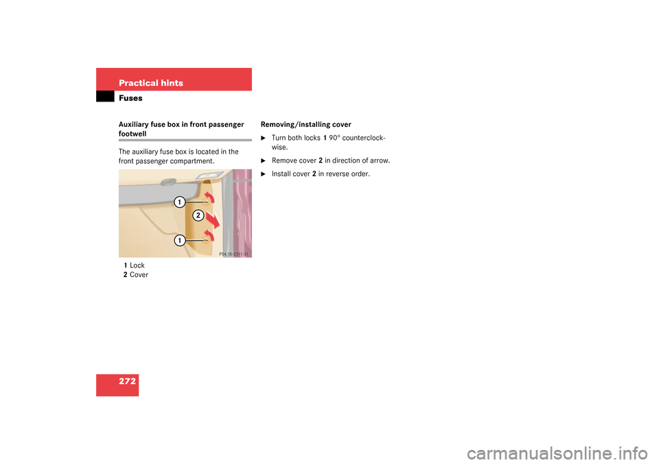
272 Practical hintsFusesAuxiliary fuse box in front passenger footwell
The auxiliary fuse box is located in the
front passenger compartment.
1Lock
2CoverRemoving/installing cover
�
Turn both locks1 90° counterclock-
wise.
�
Remove cover2 in direction of arrow.
�
Install cover2 in reverse order.
Page 291 of 321

291 Technical data
Consumer information
Consumer information
This has been prepared as required of all
manufacturers of passenger cars under Ti-
tle 49, Code of U.S. Federal Regulations,
Part 575 pursuant to the “National Traffic
and Motor Vehicle Safety Act of 1966”.Uniform tire quality grading
Quality grades can be found, where appli-
cable, on the tire sidewall between tread
shoulder and maximum section width. For
example:
All passenger car tires must conform to
federal safety requirements in addition to
these grades.Tread wear
The tread wear grade is a comparative rat-
ing based on the wear rate of the tire when
tested under controlled conditions on a
specified government test course. For ex-
ample, a tire graded 150 would wear one
a nd one-ha lf (1 ½ ) tim es as wel l on the gov-
ernment course as a tire graded 100. The
relative performance of tires depends
upon the actual conditions of their use,
however, and may depart significantly
from the norm due to variations in driving
habits, service practices and differences in
road characteristics and climate.Traction
The traction grades, from highest to lowest
are AA, A, B, and C. Those grades repre-
sent the tire’s ability to stop on wet pave-
ment as measured under controlled
conditions on specified government test
surfaces of asphalt and concrete. A tire
marked C may have poor traction perfor-
mance.Tread wear
Traction
Temperature
200
AA
A
Warning!
G
The traction grade assigned to this tire is
based on straightahead braking traction
tests, and does not include acceleration,
cornering, hydroplaning, or peak traction
characteristics.