Page 152 of 321

152 Controls in detailUseful features
Useful featuresInterior storage spaces Glove box
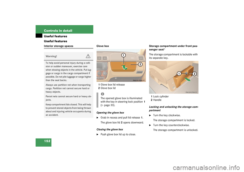
1Glove box lid release
2Glove box lid
Opening the glove box
�
Grab in recess and pull lid release1.
The glove box lid2 opens downward.
Closing the glove box
�
Push glove box lid up to close.Storage compartment under front pas-
senger seat*
The storage compartment is lockable with
its separate key.
1Lock cylinder
2Handle
Locking and unlocking the storage com-
partment
�
Turn the key clockwise.
The storage compartment is locked.
�
Turn the key counterclockwise.
The storage compartment is unlocked.
Warning!
G
To help avoid personal injury during a colli-
sion or sudden maneuver, exercise care
when stowing objects in the vehicle. Put lug-
gage or cargo in the cargo compartment if
possible. Do not pile luggage or cargo higher
than the seat backs.
Always use partition net when transporting
cargo. Partition net cannot secure hard or
heavy objects.
Parcel nets cannot secure hard or heavy ob-
jects.
Keep compartment lids closed. This will help
to prevent stored objects from being thrown
about and injuring vehicle occupants during
an accident.
iThe opened glove box is illuminated
with the key in steering lock position1
(�page 33).
Page 153 of 321
153 Controls in detail
Useful features
Opening the storage compartment �
Press the lock cylinder in and pull stor-
age compartment out using handle2.
Closing the storage compartment
�
Push the storage compartment in until
the lock engages.Armrest storage spaces
A flat storage tray with a deeper storage
compartment underneath is located below
the armrest. Both can be opened separate-
ly.
1Button to open storage tray
2Button to open storage compartment
3Open cover4Storage tray
5Coin holder
Opening the storage tray
�
Press button1 and lift up armrest.
The armrest contains two coin holders.
Opening the storage compartment
�
Press button2 and lift up armrest.
Page 154 of 321
154 Controls in detailUseful featuresOpening the storage compartment in
front of armrest�
Slide the cover3 rearward.
The storage compartment below con-
tains a cup holder (
�page 155).
Cup holders Cup holder in instrument panel
A cup holder is located on both the right
and left side of the instrument panel.
Opening the cup holder
�
Briefly touch top of cover.
The cup holder opens automatically.
Closing the cup holder
�
Fold the cup holder upwards and press
on it until it engages.
Warning!
G
When not in use, keep the cup holder
closed. Place only containers that fit into the
cup holder to prevent spills. Use lids on
open containers and do not fill containers to
a height where the contents, especially hot
liquids, could spill during vehicle maneu-
vers.
Page 158 of 321

158 Controls in detailUseful featuresElectrical outletElectrical outletOne outlet is located in the front passen-
ger footwell and another on the right-hand
side of the luggage compartment.�
Flip up cover and insert electrical plug
(cigarette lighter type).
Telephone*
Radio transmitters, such as a portable tele-
phone or a citizens band unit, should only
be used inside the vehicle if they are con-
nected to an antenna that is installed on
the outside of the vehicle.
The external antenna must be approved by
Mercedes-Benz. Please contact an autho-
rized Mercedes-Benz Light Truck Center
for information on the installation of an ap-
proved external antenna. Refer to the radio
transmitter operation instructions regard-
ing use of an external antenna.
iThe outlets function even if the key is
not in the ignition.
The electrical outlet can be used to ac-
commodate electrical consumers (e.g.
air pump, auxiliary lamps) up to a max-
imum of 180 W.
If the engine is off, the battery may be-
come discharged if used for long peri-
ods of time.
Warning!
G
Never operate radio transmitters equipped
with a built-in or attached antenna (i.e. with-
out being connected to an external antenna)
from inside the vehicle while the engine is
running. Doing so could lead to a malfunc-
tion of the vehicle’s electronic system, pos-
sibly resulting in an accident and/or serious
personal injury.
Page 169 of 321

169 Controls in detail
Useful features
Programming or reprogramming the in-
tegrated remote control�
Turn key in the steering lock to
position1 or2.
�
Hold the end of the hand-held transmit-
ter of the device you wish to train
approximately 2 to 5 inches (5 cm to
12 cm) away from the surface of the in-
tegrated remote control located on the
inside rear view mirror, keeping the in-
dicator lamp in view.
�
Using both hands, simultaneously push
the hand-held transmitter button and
the desired integrated remote control
button. Do not release the buttons until
completing next step.
�
The indicator lamp on the integrated
remote control will flash, first slowly
and then rapidly. The rapid flashing
lamp indicates successful program-
ming of the new frequency signal.
Warning!
G
When programming a garage door opener,
the door moves up or down.
When programming or operating the remote
control make sure there is no possibility of
anyone being injured by the moving door.iCertain types of garage door openers
are incompatible with the integrated
opener. If you should experience diffi-
culties with programming the transmit-
ter, contact your authorized
Mercedes-Benz Center, or call
Mercedes-Benz Customer Assistance
Center (in the USA only) at
1-800-FOR-MERCedes, or Customer
Service (in Canada) at
1-800-387-0100.
iFor operation in the USA only: This de-
vice complies with Part 15 of the
FCC Rules. Operation is subject to the
following two conditions:
(1) This device may not cause harmful
interference, and
(2) this device must accept any inter-
ference received, including interfer-
ence that may cause undesired
operation.
Any unauthorized modification to this
device could void the user’s authority
to operate the equipment.
Page 172 of 321

172 Controls in detailUseful featuresTrip computer*
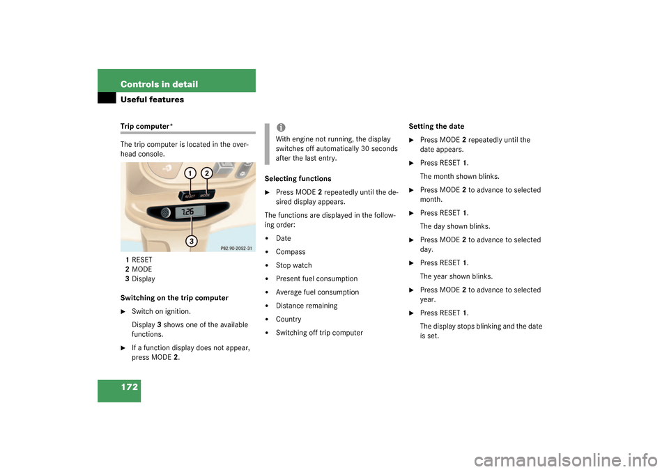
The trip computer is located in the over-
head console.
1RESET
2MODE
3Display
Switching on the trip computer�
Switch on ignition.
Display3 shows one of the available
functions.
�
If a function display does not appear,
press MODE2.Selecting functions
�
Press MODE2 repeatedly until the de-
sired display appears.
The functions are displayed in the follow-
ing order:
�
Date
�
Compass
�
Stop watch
�
Present fuel consumption
�
Average fuel consumption
�
Distance remaining
�
Country
�
Switching off trip computerSetting the date
�
Press MODE2 repeatedly until the
date appears.
�
Press RESET1.
The month shown blinks.
�
Press MODE2 to advance to selected
month.
�
Press RESET1.
The day shown blinks.
�
Press MODE2 to advance to selected
day.
�
Press RESET1.
The year shown blinks.
�
Press MODE2 to advance to selected
year.
�
Press RESET1.
The display stops blinking and the date
is set.
iWith engine not running, the display
switches off automatically 30 seconds
after the last entry.
Page 173 of 321
173 Controls in detail
Useful features
Compass
The compass displays the direction the ve-
hicle is traveling. The display3 will show
you N, NE, E, SE, S, SW, W or NW.
To ensure the display is correct, the com-
pass must be set to the proper geographic
zone (
�page 174). It may also be neces-
sary to calibrate the compass
(
�page 174).
Zone map North America Zone map South America
iThe presence of buildings, bridges,
power lines and large antenna masts
can influence the displayed values. Me-
tallic or magnetic objects in or on the
vehicle can influence the accuracy of
the compass.
Page 174 of 321

174 Controls in detailUseful featuresSetting the compass zone�
Determine the geographical point of
the vehicle with the aid of the zone
maps.
�
Switch on the ignition.
�
Press MODE2 (
�page 172) repeated-
ly until the compass display appears in
the trip computer display3.
�
Press RESET1 (
�page 172) to select
the compass zone mode.
The zone selected last is shown in the
display.
�
Press RESET1 repeatedly until the cor-
rect compass zone, as determined
from the zone map, is shown in the dis-
play.
�
Press MODE2 twice.
The new compass zone is activated and
the compass display will be shown.Calibrating the compass
If the vehicle was exposed to a significant
magnetic zone, such as high voltage power
lines, the compass may have to be calibrat-
ed.
To calibrate the compass correctly, ob-
serve the following:
�
Calibrate the compass in an area free
of steel superstructures and power
lines.
�
Switch off all electrical consumers (e.g.
exterior lamps, climate control, rear
window defroster etc.).
�
Do not open or close the slid-
ing/pop-up roof.
�
Close doors and liftgate.
�
Start and run the engine.
�
Press MODE2 (
�page 172) repeated-
ly until the compass display appears in
the trip computer display3.
�
Press RESET1 and afterwards press
MODE2.
In the display appears
CAL–
.
�
Press and hold RESET1 for approxi-
mately two seconds.
The calibration mode is activated and
the display shows
CAL
.
�
Drive without interruption two full cir-
cles at a speed between 3 mph
(5 km / h) and 7 mph (10 km / h).
The message
CAL
goes out after a short
time. The calibration is now complete.
iAn open liftgate triggers the
display
---
.