Page 171 of 321

171 Controls in detail
Useful features
Canadian programming
During programming, your hand-held
transmitter may automatically stop trans-
mitting. �
Continue to press and hold the inte-
grated remote control transmitter but-
ton (refer to steps two through four in
the “Programming” portion) while you
press and re-press (“cycle”) your
hand-held transmitter every two sec-
onds until the frequency signal has
been learned.
Upon successful training, the indicator
lamp will flash slowly and then rapidly
after several seconds.Operation of remote control
�
Turn key in steering lock to position1
or2.
�
Select and press the appropriate but-
ton to activate the remote controlled
device.
The integrated remote control trans-
mitter continues to send the signal as
long as the button is pressed – up to
20 seconds.Erasing the remote control memory
�
Turn key in steering lock to position1
or2.
�
Simultaneously hold down the left and
right side buttons for approximately
20 seconds, or until the indicator lamp
blinks rapidly.
The codes of all three channels are
erased.iIf you sell your vehicle, erase the codes
of all three channels.
Page 182 of 321
 are required by
law. These indicators are located in six
places on the tread circumference and be-
come visible at a tread")
182 OperationDriving instructionsParking
Tires
Tread wear indicators (TWI) are required by
law. These indicators are located in six
places on the tread circumference and be-
come visible at a tread depth of approxi-
mately
1/16
in (1.5 mm), at which point
the tire is considered worn and should be
replaced.
!Set the parking brake whenever park-
ing or leaving the vehicle. In addition,
move selector lever to positionP.
In addition, when parking on hills, turn
front wheel towards the curb.
Warning!
G
Do not park this vehicle in areas where com-
bustible materials such as grass, hay or
leaves can come into contact with the hot
exhaust system, as these materials could be
ignited and cause a vehicle fire.
To reduce the risk of personal injury as a re-
sult of vehicle movement, before
turning off
the engine and leaving the vehicle always:
�
Keep right foot on brake pedal.
�
Firmly depress parking brake pedal.
�
Move the selector lever to positionP.
�
Slowly release brake pedal.
�
When parked on an incline, turn front
wheel towards the road curb.
�
Turn the key to steering lock position0
and remove.
�
Take the key and lock vehicle when leav-
ing.
Warning!
G
If you feel a sudden significant vibration or
ride disturbance, or you suspect that possi-
ble damage to your vehicle has occurred,
you should turn on the hazard warning flash-
ers, carefully slow down, and drive with cau-
tion to an area which is a safe distance from
the road.
Inspect the tires and the vehicle underbody
for possible damage. If the vehicle or tires
appear unsafe, have it towed to the nearest
Mercedes-Benz Light Truck Center or tire
dealer for repairs.
Page 196 of 321
 when the air conditioning is on,
turn off th")
196 OperationDriving instructions�
If the engine coolant rises to an ex-
tremely high temperature (coolant tem-
perature needle approaching the red
zone) when the air conditioning is on,
turn off the air conditioning system.
Engine coolant heat can be additionally
vented by opening the windows,
switching the climate control fan speed
to high and setting the temperature
control to the maximum hot position.
�
Extreme care must be exercised since
your vehicle with a trailer will require
additional passing distance ahead than
when driving without a trailer.
Because your vehicle and trailer is
longer than your vehicle alone, you will
also need to go much farther ahead of
the passed vehicle before you can re-
turn to your lane.Parking
Passenger compartment
Warning!
G
To reduce the risk of personal injury, or
damage to the vehicle powertrain, as a re-
sult of vehicle/trailer movement, always:�
Keep right foot on brake pedal.
�
Shift gear selector lever to positionN.
�
Have a second person place wheel
chocks on downhill side of left and right
trailer wheels.
�
Slowly release brake pedal and let vehi-
cle and trailer roll into chocks until
stopped.
�
Firmly depress parking brake pedal.
�
Move gear selector lever to position P.
�
When parked on an incline, turn front
wheel towards the road curb.
Warning!
G
Always fasten items being carried as secure-
ly as possible.
In an accident, during hard braking or sud-
den maneuvers, loose items will be thrown
around inside the vehicle, and cause injury
to vehicle occupants unless the items are
securely fastened in the vehicle.
The trunk is the preferred place to carry ob-
jects. Always use partition net when trans-
porting cargo. Partition net cannot secure
hard or heavy objects.
Page 200 of 321

200 OperationAt the gas station
At the gas stationThe fuel filler flap is located on the
left-hand side of the vehicle towards the
rear. Locking/unlocking the vehicle with
the remote control automatically
locks/unlocks the fuel filler flap.
�
Remove the key from the steering lock.
�
Open the fuel filler flap1 by pulling in
direction of the arrow.
�
Turn the fuel cap2 to the left and hold
on to it until possible pressure is re-
leased.
�
Take off the cap.
�
Only fill your tank until the filler nozzle
unit cut out – do not top up or overfill.
�
Replace the fuel cap by turning it to the
right.
You will hear when the fuel cap is tight-
ened.
�
Close the fuel filler flap.
Warning!
G
Gasoline is highly flammable and poisonous.
It burns violently and can cause serious inju-
ry. Whenever you are around gasoline, avoid
inhaling fumes and skin contact, extinguish
all smoking materials. Never allow sparks,
flame or smoking materials near gasoline!.
!The fuel filler cap is tethered to the fuel
filler neck. Do not drop the cap. It could
damage the vehicle paint finish.!To prevent damaging the lens of the
plastic tail lamp, make certain that no
gasoline comes into contact with it.
Warning!
G
Overfilling of the fuel tank may create pres-
sure in the system which could cause a gas
discharge. This could cause the gas to spray
back out when removing the fuel pump noz-
zle, which could cause personal injury.iUse only premium unleaded gasoline
with a minimum Posted Octane Rating
of 91 (average of 96 RON / 86 MON).
Information on gasoline quality can
normally be found on the fuel pump.
More information on gasoline can be
found in the Factory Approved Service
Products pamphlet.
Page 237 of 321
237 Practical hints
Where will I find ...?
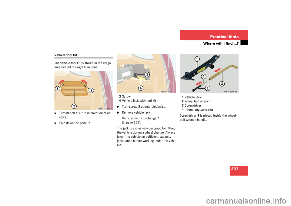
Vehicle tool kit
The vehicle tool kit is stored in the cargo
area behind the right trim panel.�
Turn handles1 90° in direction of ar-
rows.
�
Fold down the panel2.3Screw
4Vehicle jack with tool kit
�
Turn screw3 counterclockwise.
�
Remove vehicle jack.
Vehicles with CD-changer*
(�page 238).
The jack is exclusively designed for lifting
the vehicle during a wheel change. Always
lower the vehicle on sufficient capacity
jackstands before working under the vehi-
cle.1Vehicle jack
2Wheel bolt wrench
3Screwdriver
4Interchangeable slot
Screwdriver3 is placed inside the wheel-
bolt wrench handle.
Page 239 of 321

Use the spare wheel only temporarily,
while observing the following restrictions:�
Do not exceed vehicle speed of
50 mph (80")
239 Practical hints
Where will I find ...?
Spare wheel (space-saver tire)
Use the spare wheel only temporarily,
while observing the following restrictions:�
Do not exceed vehicle speed of
50 mph (80 km / h).
�
Drive to the nearest repair facility to
have the flat tire repaired or replaced
as appropriate.
�
Do not operate vehicle with more than
one spare wheel mounted.Removing spare wheel (except
ML 55 AMG)
The spare wheel is located behind the rear
bumper.
1Cover
�
Hold left and right side of cover1 and
pull away from bumper.2Screw
3Spare wheel carrier
4Lever
�
Turn screw2 counterclockwise using
the wrench (
�page 237).
Screw2 remains in spare wheel
carrier3.
�
Lift spare wheel carrier slightly and
push lever4 to the right using screw-
driver (
�page 237).
�
Swing spare wheel carrier down and
pull it out from under the bumper.
Warning!
G
The dimensions of the spare wheel are dif-
ferent from those of the road wheels. As a
result, the vehicle handling characteristics
change when driving with a mounted spare
wheel.iPlease comply with the instructions for
“Mounting the spare wheel”
(�page 255).
Warning!
G
Exercise care when removing or installing
spare wheel to prevent personal injury.
Page 253 of 321

253 Practical hints
Replacing bulbs
�
Insert reflector from the left so that it
engages on the right.
�
Position tabs of cover in slots and rein-
stall cover until properly seated.
Adjusting headlamp aim
VVertical centerline
HHeadlamp mounting high, measured
from the center Correct headlamp adjustment is extremely
important. To check and readjust a head-
lamp, follow the steps described:
�
Park the vehicle on a level surface
25 feet (7.6 m) from a vertical test
screen or wall.
�
Switch the headlamps on
(�page 102).
If the beam does not show a beam pattern
as indicated in the figure left, then follow
the steps below:
�
Open hood (
�page 202).
2Headlamp vertical adjustment screw
3Headlamp vertical adjustment screw
�
Always turn adjustment screws2
and3 simultaneously for vertical ad-
justment until the headlamp is adjust-
ed as shown1. Turn clockwise for
upward movement and counterclock-
wise for downward movement.
Graduations:
screw2:0.50° pitch
screw3:0.67° pitch
The left and right headlamps must be ad-
justed individually.
iHigh beam adjustments simultaneous-
ly aim the low beam.
Vehicle should have a normal trunk
load.
iIf it is not possible to obtain a proper
headlamp adjustment, have the system
checked at your authorized
Mercedes-Benz Light Truck Center.
Page 254 of 321
254 Practical hintsReplacing wiper blades
Replacing wiper blades
Removal�
Fold the wiper arm forward.
�
Turn wiper blade at a right angle to wip-
er arm.
1Wiper blade
2Safety tab
�
Press safety tab down2.
�
Push wiper blade downward1 and re-
move.
Installation�
Slide wiper blade into end of wiper arm
until it locks in place.
Warning!
G
For safety reasons, remove key from steer-
ing lock before replacing a wiper blade, oth-
erwise the motor could suddenly turn on and
cause injury.
!Never open the hood when the wiper
arm is folded forward.
Do not allow the wiper arms to contact
the windshield glass without a wiper
blade inserted.
Make certain that the wiper blades are
properly installed. Improperly installed
wiper blades may cause windshield
damage.
For your convenience, we recommend
that you have this work carried out by
an authorized Mercedes-Benz Light
Truck Center.