Page 133 of 321
133 Controls in detail
Automatic climate control
Adjusting side air outlets�
Turn thumbwheel4 (
�page 125), to
one of the following positions:Center air outlets
Opening
�
Turn thumbwheel center air outlet 1
(�page 125) upward to position
h
.
Closing
�
Turn thumbwheel center air outlet 1
downward to position
M
.
Use the left thumbwheel to adjust the cen-
ter air outlets on the left and in the center.
Use the right thumbwheel to adjust the
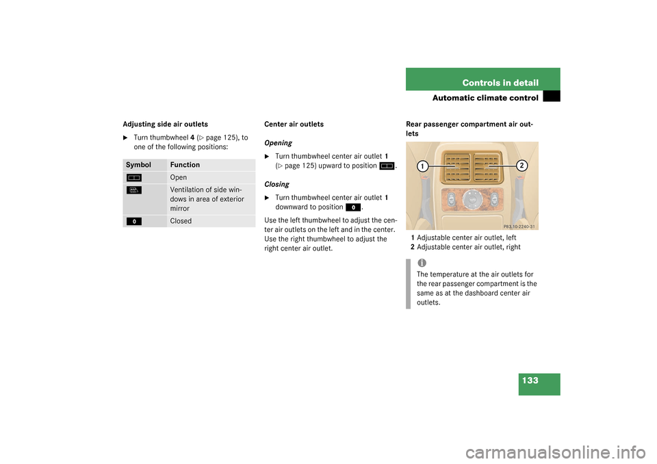
right center air outlet.Rear passenger compartment air out-
lets
1Adjustable center air outlet, left
2Adjustable center air outlet, right
Symbol
Function
h
Open
l
Ventilation of side win-
dows in area of exterior
mirror
M
Closed
iThe temperature at the air outlets for
the rear passenger compartment is the
same as at the dashboard center air
outlets.
Page 134 of 321
134 Controls in detailPower windows
Power windowsOpening and closing the side windows
The power window switches are on the
front center console.
1Left front
2Right front
3Switch for rear door window override
(
�page 69)
4Left rear
5Right rear Additional switches for the rear windows
are located on the rear center console.
6Left rear
7Right rear
To operate the power windows, turn key to
position2 (
�page 33) in the steering lock.
Warning!
G
When closing the windows, make sure that
there is no danger of anyone being harmed
by the closing procedure.
When leaving the vehicle, always remove the
key from steering lock and lock your vehicle.
Do not leave children unattended in the ve-
hicle, or with access to an unlocked vehicle.
Unsupervised use of vehicle equipment may
cause an accident and/or serious personal
injury.
Page 136 of 321

136 Controls in detailPower windowsSynchronizing power windows
The side power windows must be resyn-
chronized�
after the battery has been disconnect-
ed
�
if the windows cannot be fully opened
or closed
�
Switch ignition on.
�
Press switch
j
until the window is
completely closed and hold down for
approximately 1 second. Repeat proce-
dure for each window.
Rear quarter windows*
The switches are on the upper part of the
center console.
1Left side
2Right side
To operate the power windows, turn key to
position2 (
�page 33) in the steering lock.Opening the windows
�
Press and hold the upper part of
switches1 or2.
The window will open.
Closing the windows
�
Press and hold the lower part of
switches1 or2.
The window will close.Warning!
G
When closing the windows, make sure that
there is no danger of anyone being harmed
by the closing procedure.
When leaving the vehicle, always remove the
key from the steering lock, and lock the ve-
hicle. Do not leave children unattended in
the vehicle, or with access to an unlocked
vehicle. Unsupervised use of vehicle equip-
ment may cause an accident and/or serious
personal injury.
Page 141 of 321

141 Controls in detail
Loading
Partition net*Use of the partition net is a particularly im-
portant safety factor when the vehicle is
loaded higher than the top of the seat
backrests with smaller objects.
The partition net can be installed behind
the backrests of the front or rear seats.
Engaging partition net
1Holder
2Mounting hook
�
One after the other, press the two
mounting hooks2 inward against the
spring pressure and turn them.
The mounting hooks are locked in this
position and you can move the net into
position more easily.
�
Turn one of the mounting hooks2 in
the opposite direction.
The spring pressure will push it out.
�
Engage mounting hook2 in holder1.
�
Turn the other mounting hook and en-
gage it in the opposite holder.
�
Push both mounting hooks2 forward
into holder1.
Warning!
G
Always lock backrest in its upright position
when rear seat bench is occupied by pas-
sengers, or cargo is being carried behind the
seat bench.
To help avoid personal injury from smaller
objects flying in the occupant area during a
collision or sudden maneuver, always use
partition net when transporting cargo.
The partition net cannot prevent the move-
ment of large, heavier objects into the pas-
senger area in an accident. Such items must
be properly secured using the cargo
tie-down rings in the cargo area floor
(�page 140).
Passenger use of seats behind installed par-
tition net is restricted because of the foot-
well being taken up by the net.
Page 143 of 321
143 Controls in detail
Loading
Cargo area cover blind*
1Handle
2Holder
Closing blind�
Pull blind on handle1 across the cargo
area.
�
Guide blind into holders2.Opening blind
�
Disengage blind and guide retraction
by its handle.
Removing blind
3Button
4Mounting sleeve
�
Roll the blind up.
�
Push mounting sleeve4 inward against
spring pressure until it engages.
�
Remove blind from mounts.Installing blind
�
Place left side of blind in left mount.
�
Position right side of blind over right
mount.
�
Push button3, releasing mounting
sleeve to slide into mount.
Warning!
G
Passenger use of third row seats with cargo
area cover blind installed is restricted.
Page 150 of 321

150 Controls in detailDriving systemsMonitoring reach of sensors
The sensors must be free of dirt, ice and
snow or they will be unable to function
properly. Clean the sensors regularly with-
out scratching or damaging them.Front sensors
Rear sensors
Minimum distance
When an obstacle is located in this area, all
warning displays will light up and a warning
tone will sound. If the vehicle moves closer
than the minimum distance to an object,
the distance may no longer be displayed.Warning indicators
The warning indicators show the distance
between the sensor and the obstacle. The
warning indicators for the front area are lo-
cated above the center air outlets in the
dashboard. The warning indicator for the
rear area is located in the rear passenger
compartment lamp.
1Segments, left side of vehicle
2Segments, right side of vehicle
Each warning indicator has 6 yellow and 2
red segments.
Center
40 in (100 cm)
Corner
24 in (60 cm)
Center
48 in (120 cm)
Corner
32 in (80 cm)
Center
6 in (15 cm)
Corner
8 in (20 cm)
Page 154 of 321
154 Controls in detailUseful featuresOpening the storage compartment in
front of armrest�
Slide the cover3 rearward.
The storage compartment below con-
tains a cup holder (
�page 155).
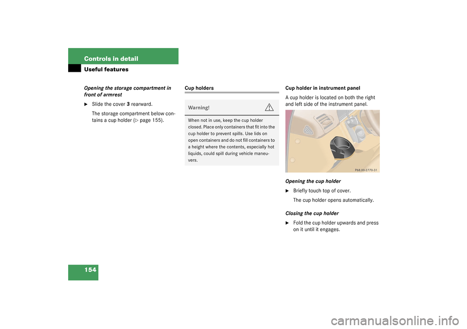
Cup holders Cup holder in instrument panel
A cup holder is located on both the right
and left side of the instrument panel.
Opening the cup holder
�
Briefly touch top of cover.
The cup holder opens automatically.
Closing the cup holder
�
Fold the cup holder upwards and press
on it until it engages.
Warning!
G
When not in use, keep the cup holder
closed. Place only containers that fit into the
cup holder to prevent spills. Use lids on
open containers and do not fill containers to
a height where the contents, especially hot
liquids, could spill during vehicle maneu-
vers.
Page 158 of 321

158 Controls in detailUseful featuresElectrical outletElectrical outletOne outlet is located in the front passen-
ger footwell and another on the right-hand
side of the luggage compartment.�
Flip up cover and insert electrical plug
(cigarette lighter type).
Telephone*
Radio transmitters, such as a portable tele-
phone or a citizens band unit, should only
be used inside the vehicle if they are con-
nected to an antenna that is installed on
the outside of the vehicle.
The external antenna must be approved by
Mercedes-Benz. Please contact an autho-
rized Mercedes-Benz Light Truck Center
for information on the installation of an ap-
proved external antenna. Refer to the radio
transmitter operation instructions regard-
ing use of an external antenna.
iThe outlets function even if the key is
not in the ignition.
The electrical outlet can be used to ac-
commodate electrical consumers (e.g.
air pump, auxiliary lamps) up to a max-
imum of 180 W.
If the engine is off, the battery may be-
come discharged if used for long peri-
ods of time.
Warning!
G
Never operate radio transmitters equipped
with a built-in or attached antenna (i.e. with-
out being connected to an external antenna)
from inside the vehicle while the engine is
running. Doing so could lead to a malfunc-
tion of the vehicle’s electronic system, pos-
sibly resulting in an accident and/or serious
personal injury.