Page 169 of 360

169 Controls in detail
Loading
Removing and installing the cover
Removing the cover�
Open latch1 on right and left side in di-
rection of arrow.
�
Pull cover 2 out upwards.
Installing the cover
�
Place cover into recesses.
�
Press right and left sides of cover down
until it locks into place.
Enlarged cargo area
The rear seat bench can be folded and low-
ered to increase the cargo area. The left,
right or both seat backrests sections may
folded down according to need.
For more information refer to “Split rear
bench seat”.
Split rear seat bench
1Lever for seat backrest sections
2Lever for seat bench sections
The rear seat bench can be folded and low-
ered to enlarge the cargo area. The left,
right or both seat backrest sections may
be folded down as required.
Warning!
G
Always lock seat backrest in its upright po-
sition when rear seat bench is occupied by
passengers, or cargo is being carried behind
the seat bench.
To help avoid personal injury from smaller
objects flying in the occupant area during a
collision or sudden maneuver, always use
partition net when transporting cargo
(�page 171).
Page 170 of 360
.
�
Pull release lever1 in direction of ar-
row and fold seat backrest forward un-
til it locks in pl")
170 Controls in detailLoading
Folding seat backrest forward�
Remove the head restraints
(�page 93).
�
Pull release lever1 in direction of ar-
row and fold seat backrest forward un-
til it locks in place.
Folding seat bench forward
�
Fold seat backrest forward.
�
Pull release lever2 in direction of ar-
row and fold seat bench forward to-
gether with the seat backrest.Returning seat bench and seat back-
rest to sitting position
�
Fold up seat bench until it locks in
place.
�
Pull release lever1 and raise seat
backrest until it locks in place.
�
Check to ensure the seat is locked by
pushing and pulling on the seat back-
rest.
Warning!
G
Failure to assure that seats and seat back-
rest are locked into place could result in an
increased chance of injury in an accident.
Never place hands under seat or near any
moving parts while a seat is being adjusted.
For safety reasons, the rear seat bench
must only be adjusted when the vehicle is
stationary.
Never ride vehicle with the tailgate open.
Deadly carbon monoxide (CO) gases may
enter vehicle interior resulting in uncon-
sciousness and death.!Before folding the seat backrest for-
ward and the rear seat bench down, be
sure that all containers in the rear cup
holder are removed.
Warning!
G
Failure to assure that seats and seat back-
rests are locked into place could result in an
increased chance of injury in an accident.
Page 172 of 360
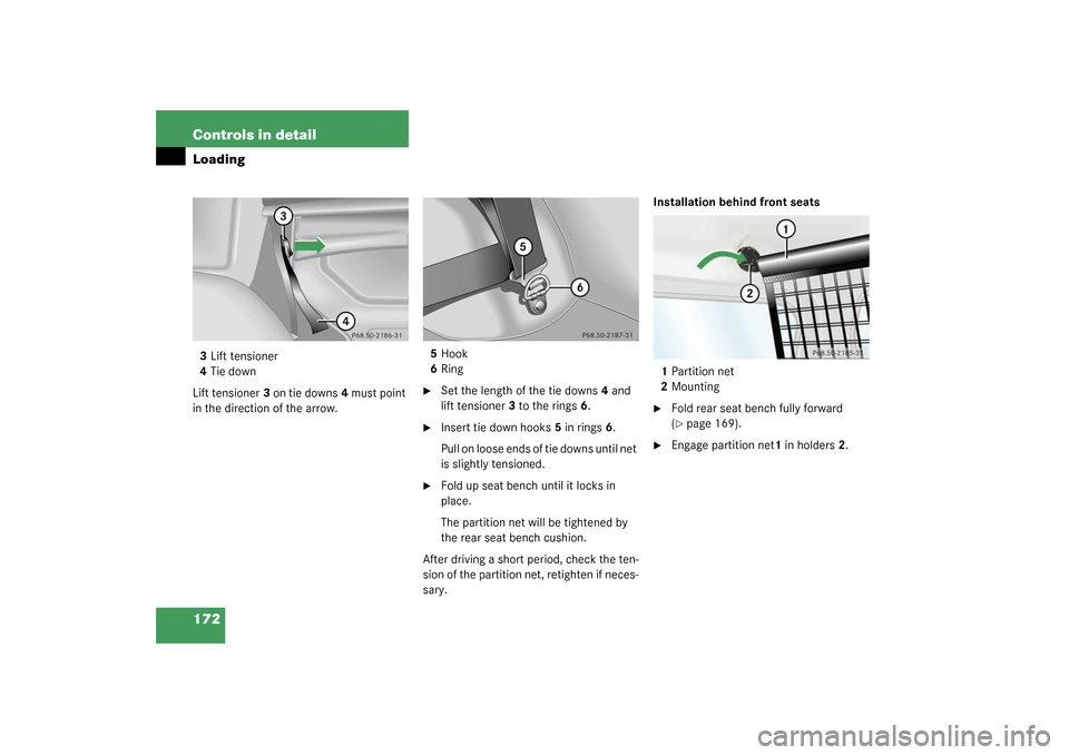
172 Controls in detailLoading3Lift tensioner
4Tie down
Lift tensioner3 on tie downs4 must point
in the direction of the arrow.5Hook
6Ring
�
Set the length of the tie downs4 and
lift tensioner3 to the rings6.
�
Insert tie down hooks5 in rings6.
Pull on loose ends of tie downs until net
is slightly tensioned.
�
Fold up seat bench until it locks in
place.
The partition net will be tightened by
the rear seat bench cushion.
After driving a short period, check the ten-
sion of the partition net, retighten if neces-
sary.Installation behind front seats
1Partition net
2Mounting
�
Fold rear seat bench fully forward
(�page 169).
�
Engage partition net1 in holders2.
Page 176 of 360

176 Controls in detailUseful features
Useful featuresInterior storage spaces
Glove box
1Unlocked position
2Locked position
3HandleOpening the glove box
�
Pull handle to open.
The glove box is illuminated with SmartKey
in starter switch position1 or2 when
opening the lid.
Closing the glove box
�
Push lid up to close.
Warning!
G
To help avoid personal injury during a colli-
sion or sudden maneuver, exercise care
when stowing objects in the vehicle. Put lug-
gage or cargo in the cargo compartment if
possible. Do not pile luggage or cargo higher
than the seat backs.
Luggage nets cannot secure hard or heavy
objects.Warning!
G
Do not load items on the roof. It may cause
instability during some maneuvers which
could result in an accident.
Warning!
G
Keep compartment lids closed. This will help
to prevent stored objects from being thrown
about and injuring vehicle occupants during
an accident and sudden maneuvers.
iThe glove box can be locked and un-
locked with the mechanical key.
Page 177 of 360
177 Controls in detail
Useful features
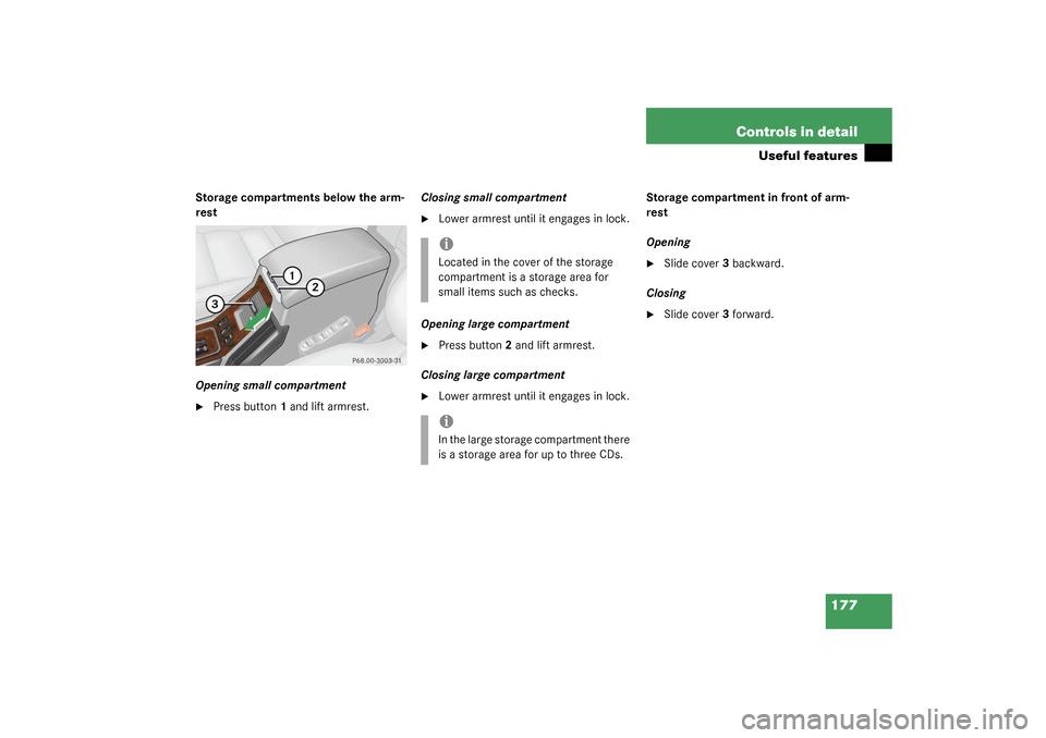
Storage compartments below the arm-
rest
Opening small compartment�
Press button1 and lift armrest.Closing small compartment
�
Lower armrest until it engages in lock.
Opening large compartment
�
Press button2 and lift armrest.
Closing large compartment
�
Lower armrest until it engages in lock.Storage compartment in front of arm-
rest
Opening
�
Slide cover3 backward.
Closing
�
Slide cover3 forward.
iLocated in the cover of the storage
compartment is a storage area for
small items such as checks.iIn the large storage compartment there
is a storage area for up to three CDs.
Page 181 of 360
181 Controls in detail
Useful features
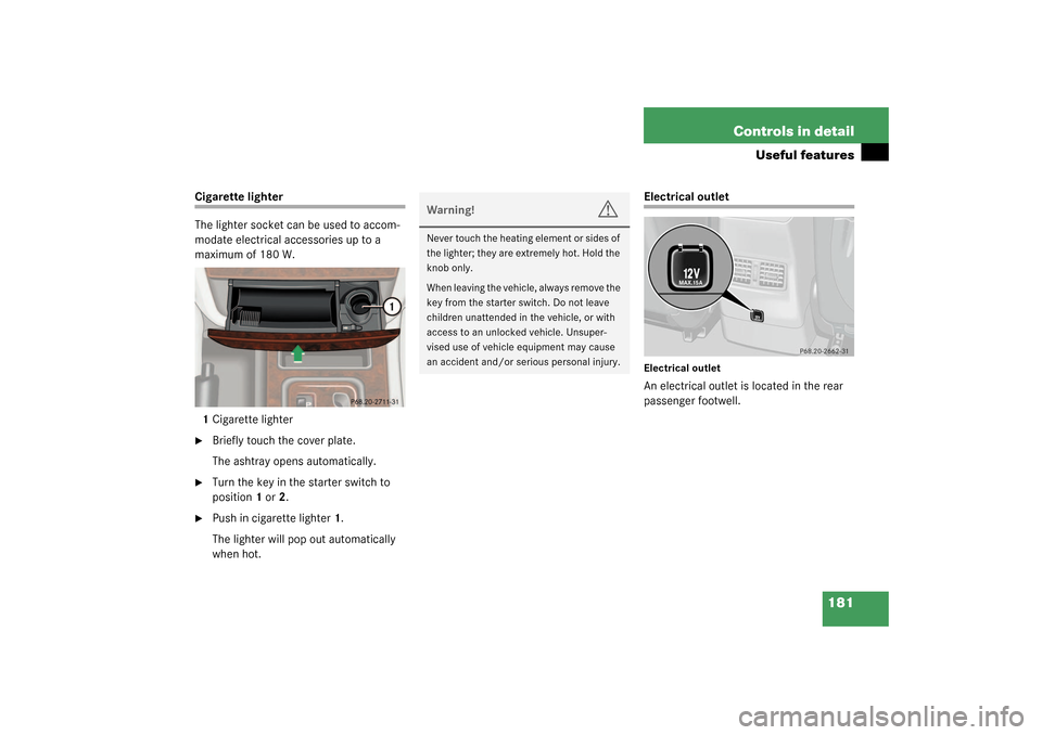
Cigarette lighter
The lighter socket can be used to accom-
modate electrical accessories up to a
maximum of 180 W.
1Cigarette lighter�
Briefly touch the cover plate.
The ashtray opens automatically.
�
Turn the key in the starter switch to
position1 or2.
�
Push in cigarette lighter1.
The lighter will pop out automatically
when hot.
Electrical outletElectrical outletAn electrical outlet is located in the rear
passenger footwell.
Warning!
G
Never touch the heating element or sides of
the lighter; they are extremely hot. Hold the
knob only.
When leaving the vehicle, always remove the
key from the starter switch. Do not leave
children unattended in the vehicle, or with
access to an unlocked vehicle. Unsuper-
vised use of vehicle equipment may cause
an accident and/or serious personal injury.
N
Page 184 of 360

184 Controls in detailUseful featuresShortly after the completion of your ac-
quaintance call, you will receive a user ID
and password via first call mail. By visiting
www.mbusa.com and selecting “Tele Aid”
(USA only), you will have access to account
information, remote door unlock, profile
and more.System self-check
Initially, after turning the key in starter
switch to position2, malfunctions are de-
tected and indicated (the indicator lamps
in the SOS button, the Roadside Assis-
tance button
•
and the Information
button
¡
stay on longer than
10 seconds or do not come on). The mes-
sage
TELE AID – VISIT WORKSHOP!
ap-
pears for approx. 10 seconds in the
multifunction display.
iThe SOS button is located above the in-
side rear view mirror.
The Roadside Assistance button
•
and the Information button
¡
are
located below the center armrest cov-
er.
!The Tele Aid system utilizes the cellular
network for communication and the
GPS (Global Positioning System) satel-
lites for vehicle location. If either of
these signals are unavailable, the
Tele Aid system may not function and if
this occurs, assistance must be sum-
moned by other means.
Warning!
G
If the indicator lamps in the SOS button, in
the Roadside Assistance button and/or in
the Information button do not come on dur-
ing the system self-check or if any of these
indicators remain illuminated constantly in
red and/or the message
TELE AID - VIS-
IT WORKSHOP
is displayed in the multifunc-
tion display after the system self-check, a
malfunction in the system has been detect-
ed.
If a malfunction is indicated as outlined
above, the system may not operate as ex-
pected. Have the system checked at the
nearest Mercedes-Benz Light Truck Center
as soon as possible.
Page 190 of 360
, and the
reserve key is not handy:�
Contact the Mercedes-Benz")
190 Controls in detailUseful features
Remote door unlock
In case you have locked your vehicle unin-
tentionally (e.g. key inside vehicle), and the
reserve key is not handy:�
Contact the Mercedes-Benz Response
Center at 1-800-756-9018 (in the USA)
or 1-888-923-8367 (in Canada).
You will be asked to provide your pass-
word which you provided when you
completed the subscriber agreement.
�
Then return to your vehicle and press
the tailgate lock for minimum of
20 seconds until the SOS button is
flashing.
The message
EMERGENCY CALL –
CALL CONNECTED appears in the multi-
function display.
As an alternative, you may unlock the vehi-
cle via Internet using the ID and password
sent to you shortly after the completion of
your acquaintance call.T h e R e s p o n s e C e n t e r w i l l t h e n u nl o c k y o u r
vehicle with the remote door unlocking
feature.
iWhen a Tele Aid call has been initiated,
the COMAND system audio is muted
and the selected mode (radio, tape or
CD) pauses. The optional cellular
phone (if installed) switches off. If you
must use this phone, the vehicle must
be parked. Disconnect the coiled cord
and place the call. The navigation sys-
tem (if engaged) will continue to run.
The display in the instrument cluster is
available for use and spoken com-
mands are only available by pressing
the RPT button on the COMAND unit. A
pop-up window will appear in the CO-
MAND display to indicate that a
Tele Aid call is in progress.
iThe remote door unlock feature is avail-
able if the relevant cellular phone net-
work is available.
The SOS button will flash and the mes-
sage
EMERGENCY CALL –
CALL CONNECTED
will appear in the mul-
tifunction display to indicate receipt of
the door unlock command.
Once the vehicle is unlocked, a Re-
sponse Center specialist will attempt
to establish voice contact with the ve-
hicle occupants.
If the tailgate lock was pressed for
more than 20 seconds before door un-
lock authorization was received by the
Response Center, you must wait
15 minutes before pressing the tailgate
lock again.