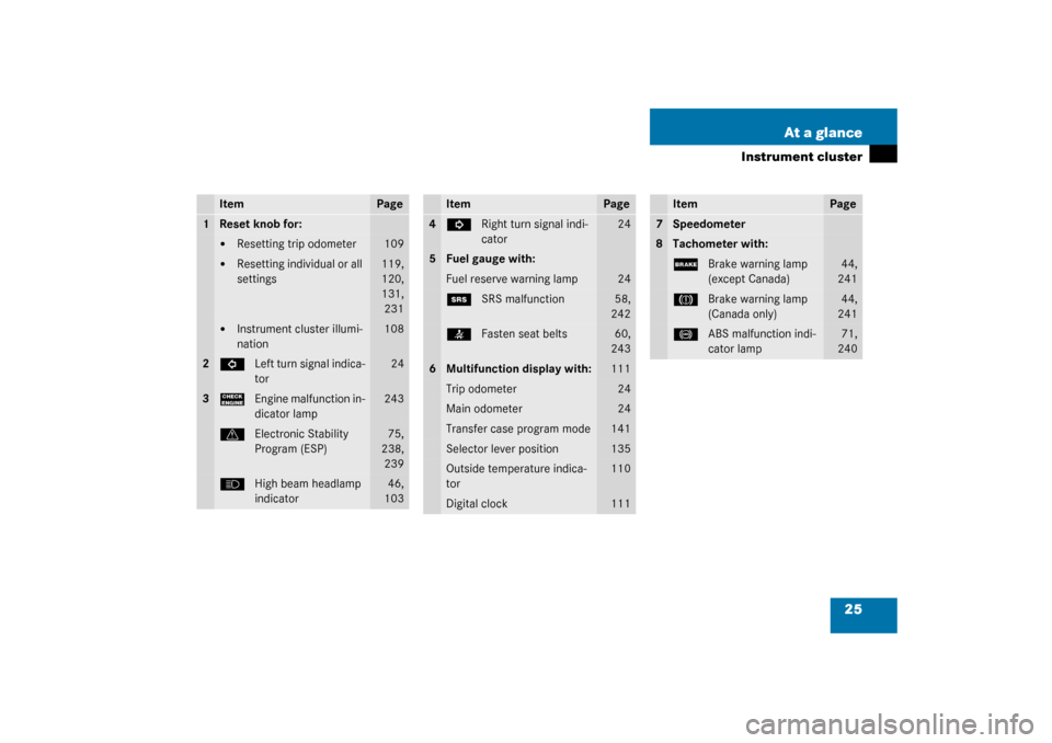
Page 25 of 360
25 At a glance
Instrument cluster
Item
Page
1
Reset knob for:�
Resetting trip odometer
109
�
Resetting individual or all
settings
119,
120,
131,
231
�
Instrument cluster illumi-
nation
108
2
L
Left turn signal indica-
tor
24
3
?
Engine malfunction in-
dicator lamp
243
v
Electronic Stability
Program (ESP)
75,
238,
239
A
High beam headlamp
indicator
46,
103
Item
Page
4
K
Right turn signal indi-
cator
24
5
Fuel gauge with:Fuel reserve warning lamp
24
1
SRS malfunction
58,
242
<
Fasten seat belts
60,
243
6
Multifunction display with:
111
Trip odometer
24
Main odometer
24
Transfer case program mode
141
Selector lever position
135
Outside temperature indica-
tor
110
Digital clock
111
Item
Page
7
Speedometer
8
Tachometer with:;
Brake warning lamp
(except Canada)
44,
241
3
Brake warning lamp
(Canada only)
44,
241
-
ABS malfunction indi-
cator lamp
71,
240
Page 108 of 360
.
1Reset knob
Th")
108 Controls in detailInstrument cluster
Instrument clusterA full view illustration of the instrument
cluster can be found in the “At a glance”
section of this manual (
�page 24).
1Reset knob
The instrument cluster is activated when
you:
�
open a door
�
turn on the ignition
�
press reset knob1
�
switch on the exterior lamps
You can change the instrument cluster set-
tings in the Instrument cluster submenu of
the control system (
�page 122).
Instrument cluster illumination
Use the reset knob to adjust the illumina-
tion brightness for the instrument cluster.
To brighten illumination�
Turn reset knob1 in the instrument
cluster clockwise.
The instrument cluster illumination will
brighten.To dim illumination
�
Turn reset knob1 in the instrument
cluster counterclockwise.
The instrument cluster illumination will
dim.
Coolant temperature display
iThe instrument cluster illumination is
dimmed or brightened automatically to
suit ambient light conditions.
The instrument cluster illumination will
also be adjusted automatically when
you switch on the vehicle’s exterior
lamps.
Warning!
G
�
Driving when your engine is badly over-
heated can cause some fluids which
may have leaked into the engine com-
partment to catch fire. You could be se-
riously burned
�
Steam from an overheated engine can
cause serious burns and can occur just
by opening the engine hood. Stay away
f r o m t h e e n g i n e i f y o u s e e o r h e a r s t e a m
coming from it.
Turn off the engine, get out of the vehicle
and do not stand near the vehicle until it
cools down.
Page 111 of 360

111 Controls in detail
Control system
Control system
The control system is activated as soon as
the key in the starter switch is turned to
position1. The control system enables you
to�
call up information about your vehicle
�
change vehicle settings
For example, you can use the control sys-
tem to find out when your vehicle is next
due for service, to set the language for
messages in the instrument cluster display
and much more.
The control system relays information to
the multifunction display.
Multifunction display
1Trip odometer
2Main odometer
3Outside temperature
4Clock
1
5Current gear selector lever position
6Transfer case program mode
Warning!
G
A driver’s attention to the road and traffic
conditions must always be his /her primary
focus when driving.
For your safety and the safety of others, se-
lecting features through the multifunction
steering wheel should only be done by the
driver when traffic and road conditions per-
mit it to be done safely.
Bear in mind that at a speed of just 30 mph
(approximately 50 km/h), your vehicle is
covering a distance of 44 feet (approximate-
ly 13.5 m) every second.
1See separate operating instructions for the
COMAND system for clock setting.
Page 276 of 360
276 Practical hintsOpening/closing in an emergency
Opening/closing in an emergencySliding/pop-up roof
You can open or close the sliding/pop-up
roof manually in the case of power failure.
The sliding/pop-up roof drive is located on
the left side of the cargo area behind the
rear panel trim.
1Edge protection
2Rear panel trim�
Open the tailgate.
�
Remove edge protection1 from door
pillar.
�
Remove rear panel trim2.3Key (vehicle tool kit)
4Screwdriver (vehicle tool kit)
�
Fit key3 into hexagon nut of drive.
�
Insert screwdriver4 into the key as a
lever.
�
Turn crank 3 clockwise to:�
close slide roof
�
raise roof at the rear
�
Turn crank 3 counterclockwise to:�
open slide roof
�
lower roof at the rear
iDo not disconnect electrical connec-
tors.
Page 282 of 360
282 Practical hintsReplacing bulbs1Protection cover
2Electrical connector (parking and
standing lamps)
3Electrical connector (high and low
beam)4Retainer spring
5Bulb for high and low beam
6Bulb socket for parking and standing
lamps
High and low beam bulb
�
Remove protection cover1.
�
Pull off electrical connector3.
�
Unclip retainer spring4.
�
Remove bulb5.
�
Insert new bulb so that the base lo-
cates in the recess on the holder.
�
Clip in retainer spring4.
�
Plug electrical connector3 onto
bulb5.
�
Press on protection cover1.
Parking and standing lamp bulb
�
Pull off electrical connector2 from
bulb6.
�
Push bulb6 into socket, turn counter-
clockwise and remove.
�
Insert new bulb6 in socket, push in
and turn clockwise until it clicks in.
�
Plug electrical connector2 onto
bulb6.
Page 284 of 360
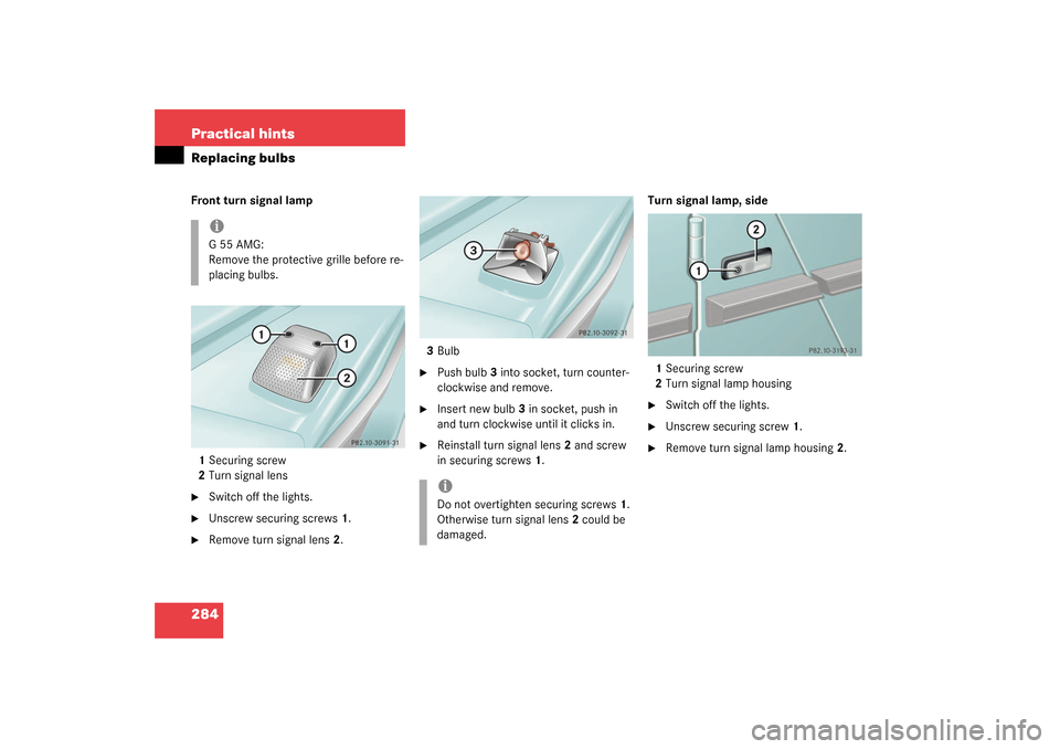
284 Practical hintsReplacing bulbsFront turn signal lamp
1Securing screw
2Turn signal lens�
Switch off the lights.
�
Unscrew securing screws1.
�
Remove turn signal lens2.3Bulb
�
Push bulb3 into socket, turn counter-
clockwise and remove.
�
Insert new bulb3 in socket, push in
and turn clockwise until it clicks in.
�
Reinstall turn signal lens2 and screw
in securing screws1.Turn signal lamp, side
1Securing screw
2Turn signal lamp housing
�
Switch off the lights.
�
Unscrew securing screw1.
�
Remove turn signal lamp housing2.
iG55AMG:
Remove the protective grille before re-
placing bulbs.
iDo not overtighten securing screws1.
Otherwise turn signal lens2 could be
damaged.
Page 286 of 360
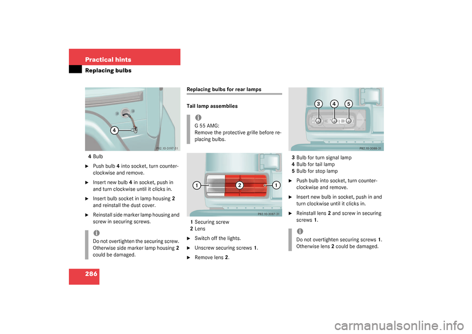
286 Practical hintsReplacing bulbs4Bulb�
Push bulb4 into socket, turn counter-
clockwise and remove.
�
Insert new bulb4 in socket, push in
and turn clockwise until it clicks in.
�
Insert bulb socket in lamp housing2
and reinstall the dust cover.
�
Reinstall side marker lamp housing and
screw in securing screws.
Replacing bulbs for rear lamps
Tail lamp assemblies
1Securing screw
2Lens�
Switch off the lights.
�
Unscrew securing screws1.
�
Remove lens2.3Bulb for turn signal lamp
4Bulb for tail lamp
5Bulb for stop lamp
�
Push bulb into socket, turn counter-
clockwise and remove.
�
Insert new bulb in socket, push in and
turn clockwise until it clicks in.
�
Reinstall lens2 and screw in securing
screws1.
iDo not overtighten the securing screw.
Otherwise side marker lamp housing2
could be damaged.
iG55AMG:
Remove the protective grille before re-
placing bulbs.
iDo not overtighten securing screws1.
Otherwise lens2 could be damaged.
Page 287 of 360
287 Practical hints
Replacing bulbs
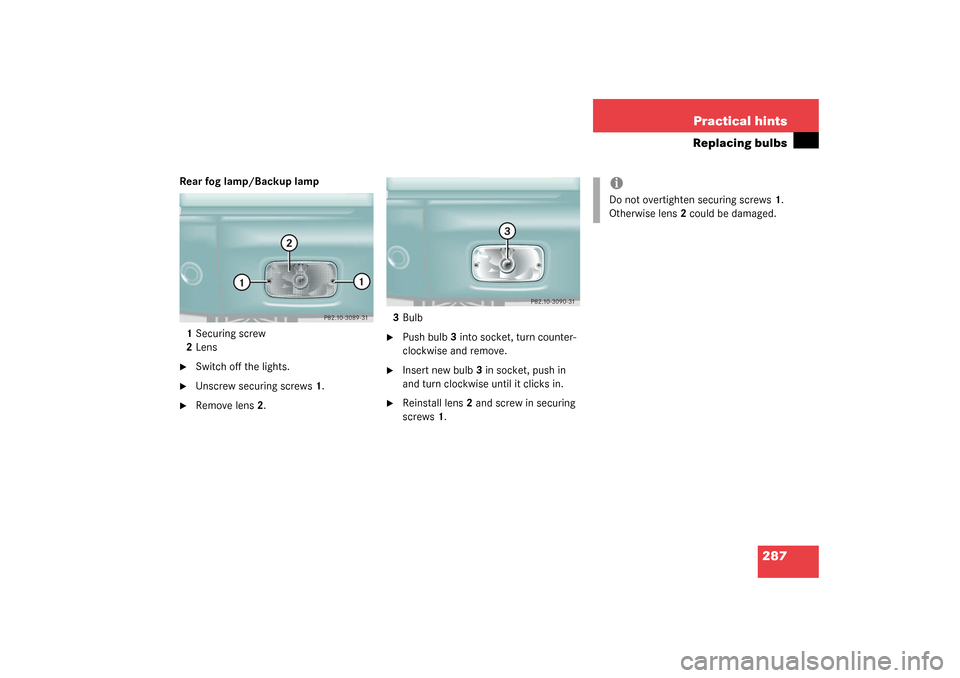
Rear fog lamp/Backup lamp
1Securing screw
2Lens�
Switch off the lights.
�
Unscrew securing screws1.
�
Remove lens2.3Bulb
�
Push bulb3 into socket, turn counter-
clockwise and remove.
�
Insert new bulb3 in socket, push in
and turn clockwise until it clicks in.
�
Reinstall lens2 and screw in securing
screws1.
iDo not overtighten securing screws1.
Otherwise lens2 could be damaged.


3Electrical connector (high and low
beam)4Retainer spring
5Bulb for high and low beam
6Bulb soc")