Page 298 of 370

304 Practical hintsFlat tireLowering the vehicle�
Lower vehicle by turning crank coun-
terclockwise until vehicle is resting ful-
ly on its own weight.
�
Remove the jack.
1-5 Wheel bolts
�
Tighten the five wheel bolts evenly, fol-
lowing the diagonal sequence illustrat-
ed (1 to5), until all bolts are tight.
Observe a tightening torque of 80 ft lb
(110 Nm).
�
Before storing the jack in the cargo
compartment, it should be fully col-
lapsed, with handle folded in.
Wheel cover on vehicles with steel rims
(Canada only)�
Position small wheel cover opening
over tire valve and press wheel cover
against wheel rim.
�
Now press (do not hit) opposite side of
wheel cover against wheel rim until
seated.
Make certain that the springs of the
wheel cover are firmly seated in the
outer rim of the steel wheel.
Warning!
G
Have the tightening torque checked after
changing a wheel. The wheels could come
loose if they are not tightened to a torque of
80 ft lb (110 Nm).
S203 MY03_A.book Page 304 Tuesday, January 28, 2003 2:22 PM
Page 300 of 370
.
�
Remove the filter box.
�
Disconnect the battery negative
lead1.
�
Remove the c")
306 Practical hintsBattery
Disconnecting the battery�
Turn off all electrical consumers.
�
Open the hood (
�page 234).
�
Remove the filter box.
�
Disconnect the battery negative
lead1.
�
Remove the cover2 from the positive
terminal.
�
Disconnect the battery positive lead.
Removing the batteries�
Remove the screw-nuts securing the
battery.
�
Remove the battery bracket.
�
Take out the battery.
Charging and reinstalling batteries�
Charge battery in accordance with the
instructions of the battery charger
manufacturer.
�
Reinstall the charged battery. Follow
the previously described steps in re-
verse order.
Warning!
G
With a disconnected battery�
y o u w i l l n o l o n g e r b e a b l e t o t u r n t h e k e y
in the starter switch
�
the selector lever will remain locked in
positionP
Warning!
G
Never charge a battery while still installed in
the vehicle. Gases may escape during charg-
ing and cause explosions that may result in
paint damage, corrosion or personal injury.
S203 MY03_A.book Page 306 Tuesday, January 28, 2003 2:22 PM
Page 301 of 370

307 Practical hints
Battery
Reconnecting the batteries�
Turn off all electrical consumers.
�
Connect the positive lead and fasten its
cover2.
�
Connect the negative lead1.
�
Reinstall the filter box.Batteries contain materials that can harm
the environment if disposed of improperly.
Large 12-volt storage batteries contain
lead. Recycling of batteries is the preferred
method of disposal. Many states require
sellers of batteries to accept old batteries
for recycling.!NEVER invert the terminal connections.!The battery, its filler caps and the vent
tube must always be securely installed
when the vehicle is in operation.
iThe following procedures must be car-
ried out following any interruption of
battery power (e.g. due to reconnec-
tion):�
Set the clock (
�page 118) (vehi-
cles with COMAND*: see COMAND
operator’s manual).
�
Resynchronize the ESP
(�page 268).
�
Resynchronize side windows
(�page 186).
�
Resynchronize sliding/pop-up roof
(�page 189).
S203 MY03_A.book Page 307 Tuesday, January 28, 2003 2:22 PM
Page 304 of 370

310 Practical hintsTowing the vehicle
Towing the vehicleMercedes-Benz recommends that the
vehicle be transported with all wheels off
the ground using flatbed or appropriate
wheel lift/dolly equipment. This method is
preferable to other types of towing.When circumstances do not permit the
recommended towing methods, the
vehicle may be towed with all wheels on
the ground or front wheels raised (except
vehicles with 4MATIC*) only so far as
necessary to have the vehicle moved to a
safe location where the recommended
towing methods can be employed.
!Use flatbed or wheel lift/dolly equip-
ment with key in starter switch turned
to position0.
Do not tow with sling-type equipment.
Towing with sling-type equipment over
bumpy roads will damage radiator and
supports.
To prevent damage during transport,
do not tie down vehicle by its chassis or
suspension parts.
Switch off the tow-away alarm
(�page 80) and deactivate the auto-
matic central locking (
�page 88).
!Vehicles with automatic transmission
and/or 4MATIC*:
Do not tow-start the vehicle.!Vehicles with 4MATIC*:
Do not tow with one axle raised. Doing
so could damage the transfer case,
which is not covered by the
Mercedes-Benz Limited Warranty.
All wheels must be on or off the ground.
Observe instructions for towing the
vehicle with all wheels on the ground.
!If the vehicle is towed with the front
axle raised (not permissible for vehicles
with 4MATIC*), the engine must be
shut off (key in starter switch
position0 or1). Otherwise the ESP will
immediately be engaged and will apply
the rear wheel brakes.
When towing the vehicle with all wheels
on the ground, the selector lever must
be in positionN (manual transmission:
gears disengaged) and the key must be
in starter switch position2.
When towing the vehicle with all wheels
on the ground or the front axle raised,
the vehicle may be towed only for
distances up to 30 miles (50 km) and
at a speed not to exceed 30 mph
(50 km/h).
S203 MY03_A.book Page 310 Tuesday, January 28, 2003 2:22 PM
Page 305 of 370

311 Practical hints
Towing the vehicle
!To be certain to avoid a possibility of
damage to the drive train, however, we
recommend the drive shaft be discon-
nected at the rear axle drive flange
(vehicles with 4MATIC*: disconnected
at the front and rear axle drive flanges)
for any towing beyond a short tow to a
nearby garage.
Warning!
G
If circumstances require towing the vehicle
with all wheels on the ground, always tow
with a tow bar if:�
the engine will not run
�
there is a malfunction in the power
supply or in the vehicle’s electrical
system
as that will be necessary to adequately
control the towed vehicle.
Prior to towing the vehicle with all wheels on
the ground, make certain that the key is in
starter switch position2.
If the key is left in starter switch position0
for an extended period of time, it can no
longer be turned in the switch. In this case,
the steering is locked. To unlock, remove
key from starter switch and reinsert.
iTo signal turns while being towed with
the hazard warning flasher in use, turn
key in starter switch to position2 and
activate the combination switch for the
left or right turn signal in the usual
manner – only the selected turn signal
will operate.
Upon canceling the turn signal, the
hazard warning flasher will operate
again.
S203 MY03_A.book Page 311 Tuesday, January 28, 2003 2:22 PM
Page 306 of 370

312 Practical hintsTowing the vehicleWarning!
G
With the engine not running, there is no
power assistance for the braking and steer-
ing systems. In this case, it is important to
keep in mind that a considerably higher
degree of effort is necessary to brake and
steer the vehicle. Adapt your driving accord-
ingly.
!When towing the vehicle with all wheels
on the ground, please note the follow-
ing:
With the automatic central locking
activated and the key in starter switch
position2, the vehicle doors lock if the
left front wheel as well as the right rear
wheel are turning at vehicle speeds of
approx. 9 mph (15 km/h) or more.
Switch off the tow-away alarm
(�page 80).
To prevent the vehicle doors from
locking, deactivate the automatic
central locking (
�page 88).
Towing of the vehicle should only be
done using the properly installed
towing eye bolt. Never attach tow
cable, tow rope or tow rod to vehicle
chassis, frame or suspension parts.
iIf the battery is disconnected or
discharged�
the key will not turn in the starter
switch. See notes on the battery
(�page 305) or on jump starting
(�page 308).
�
the selector lever will remain
locked in positionP. See notes on
manual unlocking of gear selector
lever (
�page 289).
S203 MY03_A.book Page 312 Tuesday, January 28, 2003 2:22 PM
Page 308 of 370
314 Practical hintsFuses
FusesFuse box in passenger compartmentOpening
�
Pull cover1 open with a screw driver or
similar tool.
�
Remove cover rearward.
Closing
�
Attach the cover in the front.
�
Fold the cover in until it engages.
Fuse chart
The fuse chart is found in the fuse box in
the passenger compartment. The amper-
ages of the fuses are also given there.
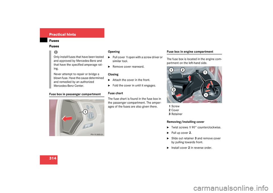
Fuse box in engine compartment
The fuse box is located in the engine com-
partment on the left-hand side.
1Screw
2Cover
3Retainer
Removing/installing cover�
Twist screws1 90° counterclockwise.
�
Pull up cover2.
�
Slide out retainer3 and remove cover
by pulling towards front.
�
Install cover2 in reverse order.
iOnly install fuses that have been tested
and approved by Mercedes-Benz and
that have the specified amperage rat-
ing.
Never attempt to repair or bridge a
blown fuse. Have the cause determined
and remedied by an authorized
Mercedes-Benz Center.
S203 MY03_A.book Page 314 Tuesday, January 28, 2003 2:22 PM
Page 309 of 370
315 Practical hintsFuses
Opening fuse box
4Fuse box cover
5Clamps�
Release clamps5.
�
Remove cover4.
Closing fuse box
�
Ensure that the sealing rubber is prop-
erly positioned.
�
Press the cover down and secure with
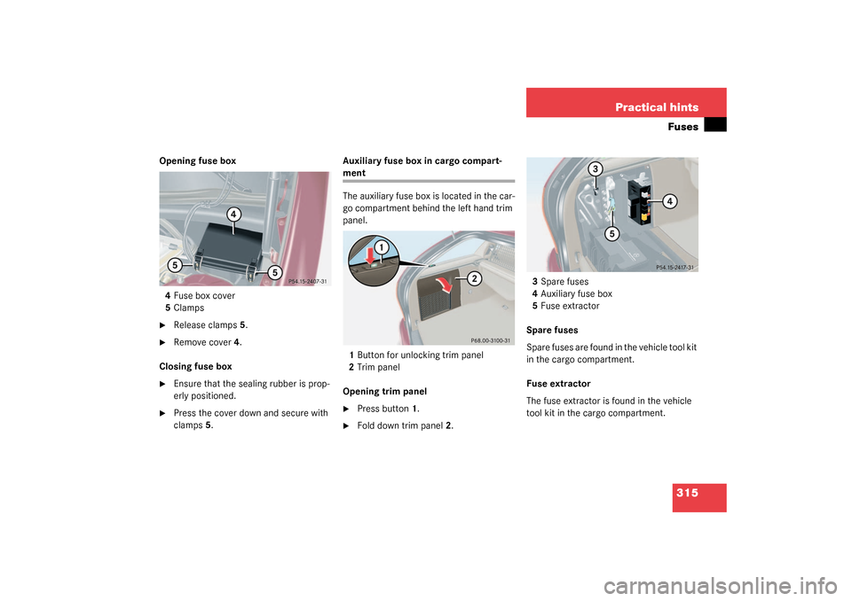
clamps5.Auxiliary fuse box in cargo compart-
ment
The auxiliary fuse box is located in the car-
go compartment behind the left hand trim
panel.
1Button for unlocking trim panel
2Trim panel
Opening trim panel�
Press button1.
�
Fold down trim panel2.3Spare fuses
4Auxiliary fuse box
5Fuse extractor
Spare fuses
Spare fuses are found in the vehicle tool kit
in the cargo compartment.
Fuse extractor
The fuse extractor is found in the vehicle
tool kit in the cargo compartment.
S203 MY03_A.book Page 315 Tuesday, January 28, 2003 2:22 PM