2003 MAZDA MODEL B-SERIES Owners Manual (in English)
-
 1
1 -
 2
2 -
 3
3 -
 4
4 -
 5
5 -
 6
6 -
 7
7 -
 8
8 -
 9
9 -
 10
10 -
 11
11 -
 12
12 -
 13
13 -
 14
14 -
 15
15 -
 16
16 -
 17
17 -
 18
18 -
 19
19 -
 20
20 -
 21
21 -
 22
22 -
 23
23 -
 24
24 -
 25
25 -
 26
26 -
 27
27 -
 28
28 -
 29
29 -
 30
30 -
 31
31 -
 32
32 -
 33
33 -
 34
34 -
 35
35 -
 36
36 -
 37
37 -
 38
38 -
 39
39 -
 40
40 -
 41
41 -
 42
42 -
 43
43 -
 44
44 -
 45
45 -
 46
46 -
 47
47 -
 48
48 -
 49
49 -
 50
50 -
 51
51 -
 52
52 -
 53
53 -
 54
54 -
 55
55 -
 56
56 -
 57
57 -
 58
58 -
 59
59 -
 60
60 -
 61
61 -
 62
62 -
 63
63 -
 64
64 -
 65
65 -
 66
66 -
 67
67 -
 68
68 -
 69
69 -
 70
70 -
 71
71 -
 72
72 -
 73
73 -
 74
74 -
 75
75 -
 76
76 -
 77
77 -
 78
78 -
 79
79 -
 80
80 -
 81
81 -
 82
82 -
 83
83 -
 84
84 -
 85
85 -
 86
86 -
 87
87 -
 88
88 -
 89
89 -
 90
90 -
 91
91 -
 92
92 -
 93
93 -
 94
94 -
 95
95 -
 96
96 -
 97
97 -
 98
98 -
 99
99 -
 100
100 -
 101
101 -
 102
102 -
 103
103 -
 104
104 -
 105
105 -
 106
106 -
 107
107 -
 108
108 -
 109
109 -
 110
110 -
 111
111 -
 112
112 -
 113
113 -
 114
114 -
 115
115 -
 116
116 -
 117
117 -
 118
118 -
 119
119 -
 120
120 -
 121
121 -
 122
122 -
 123
123 -
 124
124 -
 125
125 -
 126
126 -
 127
127 -
 128
128 -
 129
129 -
 130
130 -
 131
131 -
 132
132 -
 133
133 -
 134
134 -
 135
135 -
 136
136 -
 137
137 -
 138
138 -
 139
139 -
 140
140 -
 141
141 -
 142
142 -
 143
143 -
 144
144 -
 145
145 -
 146
146 -
 147
147 -
 148
148 -
 149
149 -
 150
150 -
 151
151 -
 152
152 -
 153
153 -
 154
154 -
 155
155 -
 156
156 -
 157
157 -
 158
158 -
 159
159 -
 160
160 -
 161
161 -
 162
162 -
 163
163 -
 164
164 -
 165
165 -
 166
166 -
 167
167 -
 168
168 -
 169
169 -
 170
170 -
 171
171 -
 172
172 -
 173
173 -
 174
174 -
 175
175 -
 176
176 -
 177
177 -
 178
178 -
 179
179 -
 180
180 -
 181
181 -
 182
182 -
 183
183 -
 184
184 -
 185
185 -
 186
186 -
 187
187 -
 188
188 -
 189
189 -
 190
190 -
 191
191 -
 192
192 -
 193
193 -
 194
194 -
 195
195 -
 196
196 -
 197
197 -
 198
198 -
 199
199 -
 200
200 -
 201
201 -
 202
202 -
 203
203 -
 204
204 -
 205
205 -
 206
206 -
 207
207 -
 208
208 -
 209
209 -
 210
210 -
 211
211 -
 212
212 -
 213
213 -
 214
214 -
 215
215 -
 216
216 -
 217
217 -
 218
218 -
 219
219 -
 220
220 -
 221
221 -
 222
222 -
 223
223 -
 224
224 -
 225
225 -
 226
226 -
 227
227 -
 228
228 -
 229
229 -
 230
230 -
 231
231 -
 232
232 -
 233
233 -
 234
234 -
 235
235 -
 236
236 -
 237
237 -
 238
238 -
 239
239 -
 240
240 -
 241
241 -
 242
242 -
 243
243 -
 244
244
 Trailer tow connector
Color Function Comment
3. Tan/White Tail lamp Relay controlled circuit
activated when the park
lamps/headlamps are on.
4. White Ground Matching vehicle circuit
returns to battery")
 ²Vehicles with trailers should not be parked on a grade. If you must
park on a grade, place wheel chocks under the trailers wheels.
Launching or retrieving a boat
Disconnect the wiring to the traile")
 4x2 equipped with automatic transmission and 4x4 vehicles:
4x2 vehicles with automatic transmissions or 4x4 vehicles with an
electronic-shift transfer case and automatic transmission, follow these
gui")
 HAZARD FLASHER
The hazard flasher is located on the
steering column, just behind the
steering wheel. The hazard flashers
will operate when the ignition is in
any position.
Push in the flasher control")
 This switch is located in the front
passengers footwell, by the kick
panel access cover.
To reset the switch:
1. Turn the ignition OFF.
2. Check the fuel system for leaks.
3. If no leaks are apparent")
 Standard fuse amperage rating and color
COLOR
Fuse
ratingMini
fusesStandard
fusesMaxi
fusesCartridge
maxi
fusesFuse link
cartridge
2A Grey Grey Ð Ð Ð
3A Violet Violet Ð Ð Ð
4A Pink Pink Ð Ð Ð")
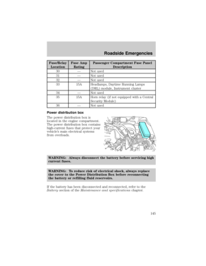
 To remove a fuse use the fuse puller tool provided.
The fuses are coded as follows:
Fuse/Relay
LocationFuse Amp
RatingPassenger Compartment Fuse Panel
Description
1 5A Power mirror switch
2 10A Daytim")
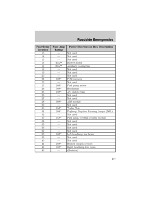
 Fuse/Relay
LocationFuse Amp
RatingPassenger Compartment Fuse Panel
Description
10 7.5A Speed control servo/amplifier assembly,
Generic Electronic Module (GEM), Shift
lock actuator, Turn signals, 4x4
1")