Page 26 of 4500
Fig. 18: Identifying Warning Light And Indicator Light
Courtesy of TOYOTA MOTOR SALES, U.S.A., INC.
Page 27 of 4500
Fig. 19: Identifying VSC Location
Courtesy of TOYOTA MOTOR SALES, U.S.A., INC.
If the indicator remains on, proceed to troubleshooting for the light circuit below.
TROUBLE AREA REFERENCE
2.SENSOR SIGNAL CHECK BY TEST MODE
HINT:
If the ignition switch is turned from ON to the ACC or LOCK position during test mode, DTC of
Trouble areaSee Procedure
ABS warning light circuitABS WARNING LIGHT CIRCUIT (REMAINS ON)
BRAKE warning light circuitBRAKE WARNING LIGHT CIRCUIT
TRAC OFF indicator light
circuitTRAC OFF INDICATOR LIGHT, TRAC OFF SWITCH
CIRCUIT
SLIP indicator light circuitSLIP INDICATOR LIGHT CIRCUIT
Page 29 of 4500
Fig. 21: ABS Warning Light Blinking Pattern
Courtesy of TOYOTA MOTOR SALES, U.S.A., INC.
5. Check that the ABS warning light blinking TEST MODE and "VSC Test" is displayed on the
multi-information display.
HINT:
If the ABS warning light and VSC information do not blink, inspect the ABS warning light
circuit and VSC warning information circuit.
TROUBLE AREA REFERENCE
6. Start the engine.
b. DECELERATION SENSOR CHECK
1. Check that the ABS warning lamp is blinking in TEST MODE.
2. Keep the vehicle in the stationar
y<00030046005200510047004c0057004c00520051000300520051000300440003004f004800590048004f0003005600580055004900440046004800030049005200550003001400030056004800460052005100470003005200550003005000520055004800
110003[
Trouble areaSee Procedure
ABS warning light circuitABS WARNING LIGHT CIRCUIT (DOES NOT
LIGHT UP)
VSC warning information
circuitVSC WARNING LIGHT CIRCUIT (DOES NOT
LIGHT UP)
Page 30 of 4500
HINT:
The blinking pattern of the ABS warning lamp and the "VSC Test" display on the multi-
information do not change. When the sensor is normal and in the test mode, if the above conditions
are met, the check is completed.
Fig. 22: Identifying VSC Test Location
Courtesy of TOYOTA MOTOR SALES, U.S.A., INC.
c. CHECK THE MASTER CYLINDER PRESSURE SENSOR
1. Leaving the vehicle in a stationary condition engine is off and the brake pedal in a free
condition for 1 second. or more, continue to quickly depress the brake pedal with a force of
98 N (10 kgf, 22 lbf) or more for 1 second, or more.
HINT:
At this time, the ABS warnin
g light stays on for 3 seconds.
Page 33 of 4500
Fig. 24: Identifying VSC Test Location
Courtesy of TOYOTA MOTOR SALES, U.S.A., INC.
e. BRAKE PEDAL LOAD SENSING SWITCH CHECK
1. Keep depressing the brake pedal for one second or more with a brake pedal load of
approximately 59 N (6kgf) with the ignition switch in the ON position (engine is off).
2. Check if the brake warning lamp comes on and the ABS motor operating sound can be heard.
HINT:
If rechecking the brake pedal load sensing switch after the engine starts, exit the test mode
and enter the test mode to release the negative pressure in the booster by pumping the brake
pedal.
3. Start the engine and depress the brake pedal with a brake pedal load of approximately 59 N
(6 kgf) or more to check if the brake warning lamp goes off.
f. SPEED SENSOR CHECK
1. Check the ABS warnin
g lamp is blinking in TEST MODE.
Page 34 of 4500
2. Drive the vehicle straight forward.
Drive the vehicle at a speed of 28 to 50 mph (45 to 80 km/h) or higher for several seconds and
check that the ABS warning light goes off.
Fig. 25: Identifying ABS Warning Light Blinking Pattern
Courtesy of TOYOTA MOTOR SALES, U.S.A., INC.
VEHICLE SPEED SPECIFICATIONS
HINT:
Vehicle SpeedTestCheck
0 to 28 mph (0 to 45 km/h)Low speed testResponse of sensors
28 to 50 mph (45 to 80 km/h)Middle speed testDeviations of sensor signal
Page 35 of 4500
If the speed sensor check is completed, the ABS warning lamp does not come on while driving and
blinks at test mode when the vehicle stops.
g. END OF SENSOR CHECK
1. If the sensor check is completed, the ABS warning lamp blinks (test mode) when the vehicle
stops and the ABS warning lamp is off when the vehicle is driving.
h. READ TEST MODE CODE
1. Using hand-held tester, check the DTCs in the test mode. (Refer to the step i)
HINT:
The test mode codes and DTCs are displayed.
If the ABS is normal, the ABS warning lamp comes on for 0.25 seconds and goes off for
0.25 seconds repeatedly.
If the VSC system is normal, the multi-information displays "VSC OK".
Page 39 of 4500

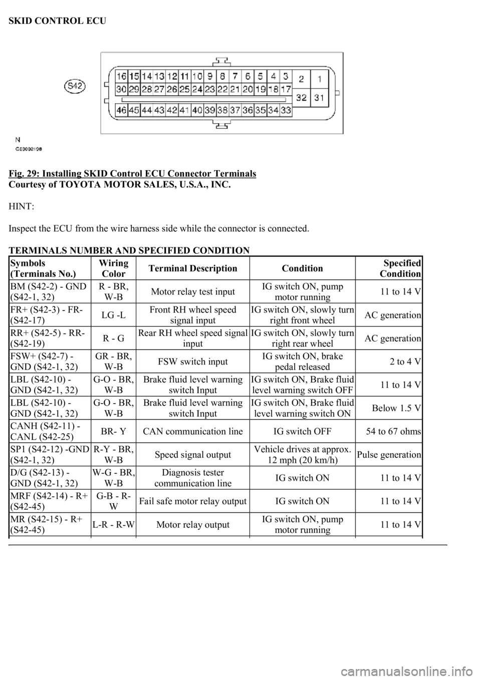
SKID CONTROL ECU
Fig. 29: Installing SKID Control ECU Connector Terminals
Courtesy of TOYOTA MOTOR SALES, U.S.A., INC.
HINT:
Inspect the ECU from the wire harness side while the connector is connected.
TERMINALS NUMBER AND SPECIFIED CONDITION
Symbols
(Terminals No.)Wiring
ColorTerminal DescriptionConditionSpecified
Condition
BM (S42-2) - GND
(S42-1, 32)R - BR,
W-BMotor relay test inputIG switch ON, pump
motor running11 to 14 V
FR+ (S42-3) - FR-
(S42-17)LG -LFront RH wheel speed
signal inputIG switch ON, slowly turn
right front wheelAC generation
RR+ (S42-5) - RR-
(S42-19)R - GRear RH wheel speed signal
inputIG switch ON, slowly turn
right rear wheelAC generation
FSW+ (S42-7) -
GND (S42-1, 32)GR - BR,
W-BFSW switch inputIG switch ON, brake
pedal released2 to 4 V
LBL (S42-10) -
GND (S42-1, 32)G-O - BR,
W-BBrake fluid level warning
switch InputIG switch ON, Brake fluid
level warning switch OFF11 to 14 V
LBL (S42-10) -
GND (S42-1, 32)G-O - BR,
W-BBrake fluid level warning
switch InputIG switch ON, Brake fluid
level warning switch ONBelow 1.5 V
CANH (S42-11) -
CANL (S42-25)BR- YCAN communication lineIG switch OFF54 to 67 ohms
SP1 (S42-12) -GND
(S42-1, 32)R-Y - BR,
W-BSpeed signal outputVehicle drives at approx.
12 mph (20 km/h)Pulse generation
D/G (S42-13) -
GND (S42-1, 32)W-G - BR,
W-BDiagnosis tester
communication lineIG switch ON11 to 14 V
MRF (S42-14) - R+
(S42-45)G-B - R-
WFail safe motor relay outputIG switch ON11 to 14 V
MR (S42-15) - R+
(S42-45)L-R - R-WMotor relay outputIG switch ON, pump
motor running11 to 14 V