Page 3967 of 4500
OPERATION AND TILT AND TELESCOPIC POSITION OPERATION
HINT:
*1: Wireless door lock control system
*2: Smart key system
If the result is not as specified, inspect the tilt and telescopic.
4.CHECK FRONT POWER SEAT FUNCTION
a. Check the basic functions.
1. Operate the power seat switches and check to make sure each seat function works:
Sliding
Front vertical
Lifter
Reclining
Lumbar support
Cushion sliding
Headrest
OperationTilt and Telescopic Position Operation
Key is inserted to the key cylinder*1 Engine switch is
pushed*2Vertical tilt position
Key is inserted to the key cylinder*1 Engine switch is
pushed*2Telescopic flexibility (lengthening and
shortening)
Page 3969 of 4500

(SLIDING, FRONT VERTICAL, LIFTER, RECLINING, CUSHION SLIDING AND
HEADREST)
a. Check the PTC operation inside the power seat motor.
HINT:
The PTC thermistor's resistance increases when the power seat switch is held down even after the power
seat has been moved to the maximum in one direction. After the resistance increases, current is shut off to
prevent a short circuit.
1. Choose a power seat function. Operate the power seat switch and move the seat to the maximum in
one direction. Keep the seat in that position for approximately 60 seconds.
2. Operate the power seat switch again and continue to try to move the seat in the same direction as in
step (1). Measure the amount of time elapsed before the electrical current is automatically cut.
Check if electrical current has shut off by making sure the sound of the motor has stopped.
Standard:
ITEM AND SPECIFIED CONDITION
3. After the current has stopped, release the power seat switch and wait for approximately 60 seconds.
4. Operate the same power seat switch and move the seat to the opposite extreme of direction in step
(1). Check that the motor operates.
6.CHECK LUMBAR SUPPORT ADJUSTER ASSY
a. Check the PTC operation inside the power seat motor.
1. Operate the lumbar support switch and move the lumbar support to either the foremost or
rearmost position. Keep the seat in that position for approximately 60 seconds.
2. Operate the lumbar support switch again and continue to try to move the lumbar support in
the same direction as in step (1). Measure the amount of time elapsed before the electrical
current is automatically cut. Check if electrical current has shut off by making sure the sound
of the motor has stopped.
Standard: 4 to 90 seconds
ItemSpecified Condition
Headrest only4 to 60 seconds
Others4 to 90 seconds
Page 3970 of 4500

3. After the current has stopped, release the lumbar support switch and wait for approximately
60 seconds.
4. Operate the lumbar support switch and move the seat to the opposite extreme of direction in
step (1). Check that the motor operates.
7.CHECK MEMORY AND REACTIVATION FUNCTION
a. Turn the ignition switch ON and move the shift lever into the P position.
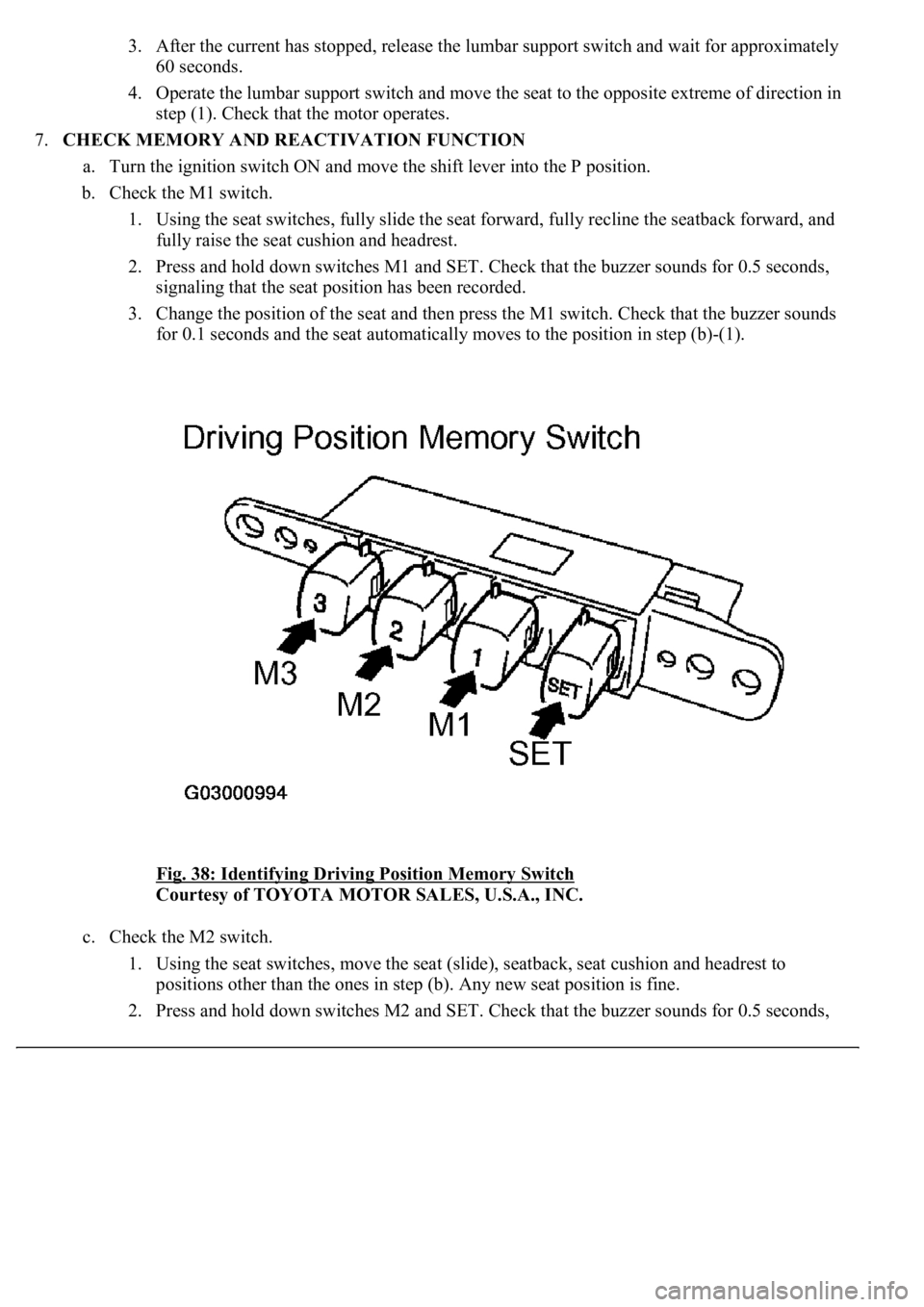
b. Check the M1 switch.
1. Using the seat switches, fully slide the seat forward, fully recline the seatback forward, and
fully raise the seat cushion and headrest.
2. Press and hold down switches M1 and SET. Check that the buzzer sounds for 0.5 seconds,
signaling that the seat position has been recorded.
3. Change the position of the seat and then press the M1 switch. Check that the buzzer sounds
for 0.1 seconds and the seat automatically moves to the position in step (b)-(1).
<0029004c004a001100030016001b001d0003002c0047004800510057004c0049005c004c0051004a000300270055004c0059004c0051004a0003003300520056004c0057004c00520051000300300048005000520055005c00030036005a004c0057004600
4b[
Courtesy of TOYOTA MOTOR SALES, U.S.A., INC.
c. Check the M2 switch.
1. Using the seat switches, move the seat (slide), seatback, seat cushion and headrest to
positions other than the ones in step (b). Any new seat position is fine.
2. Press and hold down switches M2 and SET. Check that the buzzer sounds for 0.5 seconds,
Page 3977 of 4500
Courtesy of TOYOTA MOTOR SALES, U.S.A., INC.
3.Driver's seat:
INSPECT LUMBAR SUPPORT SWITCH
a. Measure the resistance between the terminals when the switch is operated.
Standard:
Upper side control
TESTER CONNECTION AND SPECIFIED CONDITION
Tester ConnectionSwitch ConditionSpecified Condition
1 (H) - 5 (B)HOLDBelow 1ohms
4 (R) - 6 (E)HOLDBelow 1ohms
1 (H) - 6 (E)OFFBelow 1ohms
4 (R) - 6 (E)OFFBelow 1ohms
1 (H) - 6 (E)RELEASEBelow 1ohms
4 (R) - 5 (B)RELEASEBelow 1ohms
Page 3979 of 4500
Fig. 41: Identifying Lumbar Support Switch Connector Terminals -Driver Seat
Courtesy of TOYOTA MOTOR SALES, U.S.A., INC.
Lower side control
TESTER CONNECTION AND SPECIFIED CONDITION
If the result is not as specified, replace the switch.
4.Passenger's seat:
INSPECT LUMBAR SUPPORT SWITCH
a. Measure the resistance between the terminals when the switch is operated.
Standard:
TESTER CONNECTION AND SPECIFIED CONDITION
If the result is not as specified, replace the switch.
Tester ConnectionSwitch ConditionSpecified Condition
2 (H1) - 5 (B)HoldBelow 1ohms
3 (R1) - 6 (E)HoldBelow 1ohms
2 (H1) - 6 (E)OFFBelow 1ohms
3 (R1) - 6 (E)OFFBelow 1ohms
2 (H1) - 6 (E)RELEASEBelow 1ohms
3 (R1) - 5 (B)RELEASEBelow 1ohms
Tester ConnectionSwitch ConditionSpecified Condition
1 (B) - 4 (H)HOLDBelow 1 ohms
2 (E) - 3 (R)HOLDBelow 1 ohms
1 (B) - 3 (R)OFFBelow 1 ohms
2 (E) - 3 (R)OFFBelow 1 ohms
1 (B) - 3 (R)RELEASEBelow 1 ohms
2 (E) - 4 (H)RELEASEBelow 1 ohms
Page 3980 of 4500
Fig. 42: Identifying Lumbar Support Switch Connector Terminals - Passenger Seat
Courtesy of TOYOTA MOTOR SALES, U.S.A., INC.
5.Driver's seat:
INSPECT POWER SEAT CUSHION SWITCH
a. Measure the resistance between the terminals when the switch is operated.
b. Remove the power seat cushion switch.
c. Measure the resistance of the switch.
Standard:
TESTER CONNECTION AND SPECIFIED CONDITION
If the result is not as specified, replace the switch.
Tester ConnectionSwitch ConditionSpecified Condition
1 (CSNF) - 4 (E)FRONTBelow 1 ohms
1 (CSNF) - 4 (E), 2 (CSNR) -4 (E)OFF10 kohms higher
2 (CSNR) - 4 (E)REARBelow 1 ohms
Page 3988 of 4500
OK:
MEASUREMENT CONDITION AND SPECIFIED CONDITION
If the result is not as specified, replace the cushion slide motor.
Fig. 49: Checking Operation Of Cushion Slide Motor
Courtesy of TOYOTA MOTOR SALES, U.S.A., INC.
8.INSPECT POWER SEAT MOTOR (LUMBAR SUPPORT)
a. Check operation of the lumbar support adjuster motor.
1. Check if the motor rotates smoothl
y when the battery is connected to the lumbar support
Measurement ConditionSpecified Condition
Battery positive (+) --> 1 Battery negative (-) --> 2Counterclockwise
Battery positive (+) --> 2 Battery negative (-) --> 1Clockwise
Page 3989 of 4500
adjuster motor connector terminals.
OK:
MEASUREMENT CONDITION AND SPECIFIED CONDITION
If the result is not as specified, replace the adjuster motor.
Fig. 50: Checking Operation Of Lumbar Support Adjuster Motor
Courtesy of TOYOTA MOTOR SALES, U.S.A., INC.
9.INSPECT POWER SEAT MOTOR (HEADREST)
a. Check operation of the headrest motor.
1. Check if the motor rotates smoothly when the battery is connected to the headrest motor
connector terminals.
Measurement ConditionSpecified Condition
Battery positive (+) --> 1 Battery negative (-) --> 2Clockwise
Battery positive (+) --> 2 Battery negative (-) --> 1Counterclockwise