Page 1988 of 4500
Fig. 44: Removing Cruise Control Main Switch Assy
Courtesy of TOYOTA MOTOR SALES, U.S.A., INC.
7.INSPECT STEERING WHEEL CENTER POINT
8.INSTALL STEERING WHEEL ASSY (See step 96 in OVERHAUL
)
9.INSTALL HORN BUTTON ASSY (See step 6 in REPLACEMENT
)
10.CONNECT BATTERY NEGATIVE TERMINAL
11.INSPECT HORN BUTTON ASSY
12.INSPECT SRS WARNING LIGHT
Page 2635 of 4500

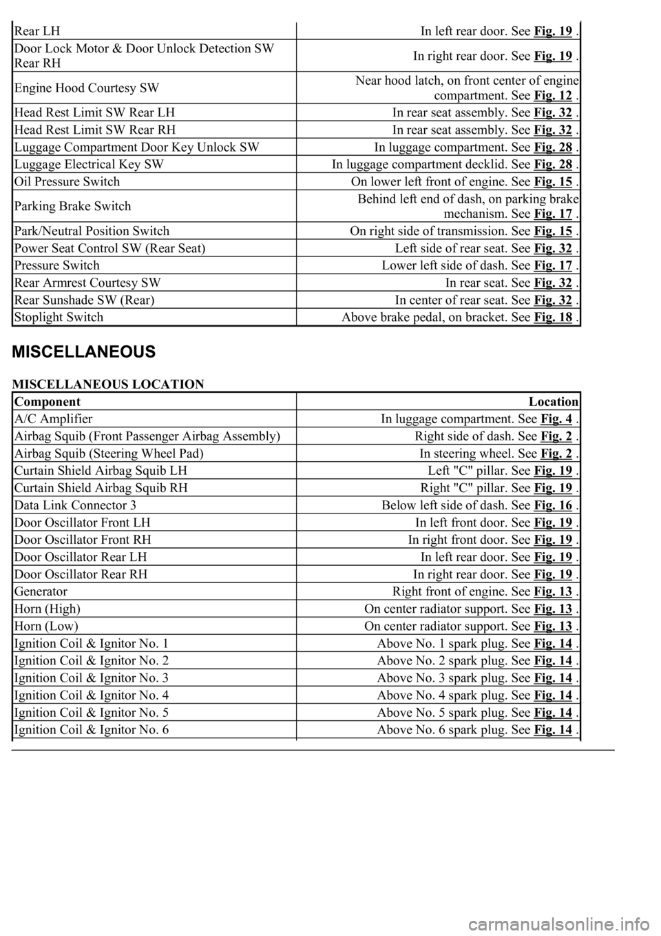
MISCELLANEOUS LOCATION
Rear LHIn left rear door. See Fig. 19 .
Door Lock Motor & Door Unlock Detection SW
Rear RHIn right rear door. See Fig. 19 .
Engine Hood Courtesy SWNear hood latch, on front center of engine
compartment. See Fig. 12
.
Head Rest Limit SW Rear LHIn rear seat assembly. See Fig. 32 .
Head Rest Limit SW Rear RHIn rear seat assembly. See Fig. 32 .
Luggage Compartment Door Key Unlock SWIn luggage compartment. See Fig. 28 .
Luggage Electrical Key SWIn luggage compartment decklid. See Fig. 28 .
Oil Pressure SwitchOn lower left front of engine. See Fig. 15 .
Parking Brake SwitchBehind left end of dash, on parking brake
mechanism. See Fig. 17
.
Park/Neutral Position SwitchOn right side of transmission. See Fig. 15 .
Power Seat Control SW (Rear Seat)Left side of rear seat. See Fig. 32 .
Pressure SwitchLower left side of dash. See Fig. 17 .
Rear Armrest Courtesy SWIn rear seat. See Fig. 32 .
Rear Sunshade SW (Rear)In center of rear seat. See Fig. 32 .
Stoplight SwitchAbove brake pedal, on bracket. See Fig. 18 .
ComponentLocation
A/C AmplifierIn luggage compartment. See Fig. 4 .
Airbag Squib (Front Passenger Airbag Assembly)Right side of dash. See Fig. 2 .
Airbag Squib (Steering Wheel Pad)In steering wheel. See Fig. 2 .
Curtain Shield Airbag Squib LHLeft "C" pillar. See Fig. 19 .
Curtain Shield Airbag Squib RHRight "C" pillar. See Fig. 19 .
Data Link Connector 3Below left side of dash. See Fig. 16 .
Door Oscillator Front LHIn left front door. See Fig. 19 .
Door Oscillator Front RHIn right front door. See Fig. 19 .
Door Oscillator Rear LHIn left rear door. See Fig. 19 .
Door Oscillator Rear RHIn right rear door. See Fig. 19 .
GeneratorRight front of engine. See Fig. 13 .
Horn (High)On center radiator support. See Fig. 13 .
Horn (Low)On center radiator support. See Fig. 13 .
Ignition Coil & Ignitor No. 1Above No. 1 spark plug. See Fig. 14 .
Ignition Coil & Ignitor No. 2Above No. 2 spark plug. See Fig. 14 .
Ignition Coil & Ignitor No. 3Above No. 3 spark plug. See Fig. 14 .
Ignition Coil & Ignitor No. 4Above No. 4 spark plug. See Fig. 14 .
Ignition Coil & Ignitor No. 5Above No. 5 spark plug. See Fig. 14 .
Ignition Coil & Ignitor No. 6Above No. 6 spark plug. See Fig. 14 .
Page 2637 of 4500

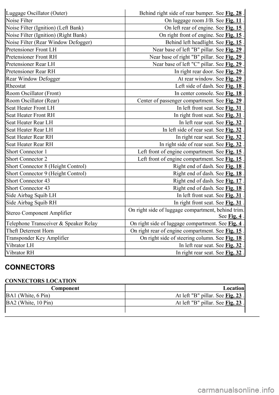
CONNECTORS LOCATION
Luggage Oscillator (Outer)Behind right side of rear bumper. See Fig. 28 .
Noise FilterOn luggage room J/B. See Fig. 11 .
Noise Filter (Ignition) (Left Bank)On left rear of engine. See Fig. 15 .
Noise Filter (Ignition) (Right Bank)On right front of engine. See Fig. 15 .
Noise Filter (Rear Window Defogger)Behind left headlight. See Fig. 15 .
Pretensioner Front LHNear base of left "B" pillar. See Fig. 29 .
Pretensioner Front RHNear base of right "B" pillar. See Fig. 29 .
Pretensioner Rear LHNear base of left "C" pillar. See Fig. 29 .
Pretensioner Rear RHIn right rear door. See Fig. 29 .
Rear Window DefoggerAt rear window. See Fig. 29 .
RheostatLeft side of dash. See Fig. 18 .
Room Oscillator (Front)In center console. See Fig. 18 .
Room Oscillator (Rear)Center of passenger compartment. See Fig. 29 .
Seat Heater Front LHIn left front seat. See Fig. 31 .
Seat Heater Front RHIn right front seat. See Fig. 31 .
Seat Heater Rear LHIn left rear seat. See Fig. 32 .
Seat Heater Rear LHIn left side of rear seat. See Fig. 32 .
Seat Heater Rear RHIn right rear seat. See Fig. 32 .
Seat Heater Rear RHIn right side of rear seat. See Fig. 32 .
Short Connector 1Left front of engine compartment. See Fig. 15 .
Short Connector 2Left front of engine compartment. See Fig. 15 .
Short Connector 8 (Height Control)Right end of dash. See Fig. 18 .
Short Connector 9 (Height Control)Right end of dash. See Fig. 18 .
Short Connector 43Right end of dash. See Fig. 17 .
Short Connector 43Right end of dash. See Fig. 18 .
Side Airbag Squib LHIn left front seat. See Fig. 31 .
Side Airbag Squib RHIn right front seat. See Fig. 31 .
Stereo Component AmplifierOn right side of luggage compartment, behind trim.
See Fig. 4
.
Telephone Transceiver & Speaker RelayOn right side of luggage compartment. See Fig. 4 .
Theft Deterrent HornOn right rear of engine compartment. See Fig. 15 .
Transponder Key AmplifierOn right side of steering column. See Fig. 18 .
Vibrator LHIn left rear seat. See Fig. 32 .
Vibrator RHIn right rear seat. See Fig. 32 .
ComponentLocation
BA1 (White, 6 Pin)At left "B" pillar. See Fig. 23 .
BA2 (White, 10 Pin)At left "B" pillar. See Fig. 23 .
Page 4163 of 4500

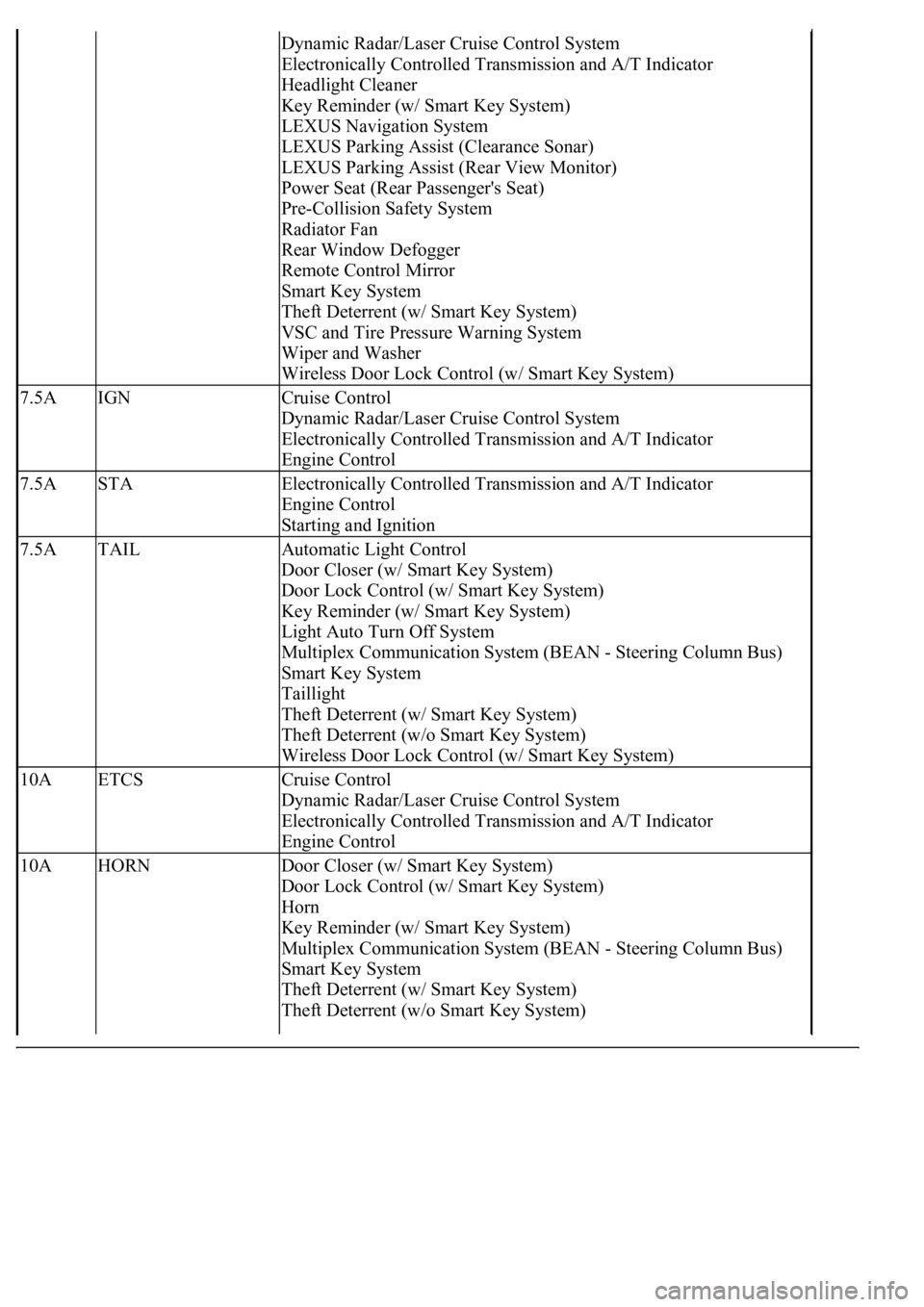
Dynamic Radar/Laser Cruise Control System
Electronically Controlled Transmission and A/T Indicator
Headlight Cleaner
Key Reminder (w/ Smart Key System)
LEXUS Navigation System
LEXUS Parking Assist (Clearance Sonar)
LEXUS Parking Assist (Rear View Monitor)
Power Seat (Rear Passenger's Seat)
Pre-Collision Safety System
Radiator Fan
Rear Window Defogger
Remote Control Mirror
Smart Key System
Theft Deterrent (w/ Smart Key System)
VSC and Tire Pressure Warning System
Wiper and Washer
Wireless Door Lock Control (w/ Smart Key System)
7.5AIGNCruise Control
Dynamic Radar/Laser Cruise Control System
Electronically Controlled Transmission and A/T Indicator
Engine Control
7.5ASTAElectronically Controlled Transmission and A/T Indicator
Engine Control
Starting and Ignition
7.5ATAILAutomatic Light Control
Door Closer (w/ Smart Key System)
Door Lock Control (w/ Smart Key System)
Key Reminder (w/ Smart Key System)
Light Auto Turn Off System
Multiplex Communication System (BEAN - Steering Column Bus)
Smart Key System
Taillight
Theft Deterrent (w/ Smart Key System)
Theft Deterrent (w/o Smart Key System)
Wireless Door Lock Control (w/ Smart Key System)
10AETCSCruise Control
Dynamic Radar/Laser Cruise Control System
Electronically Controlled Transmission and A/T Indicator
Engine Control
10AHORNDoor Closer (w/ Smart Key System)
Door Lock Control (w/ Smart Key System)
Horn
Key Reminder (w/ Smart Key System)
Multiplex Communication System (BEAN - Steering Column Bus)
Smart Key System
Theft Deterrent (w/ Smart Key System)
Theft Deterrent (w/o Smart Key System)
Page 4172 of 4500

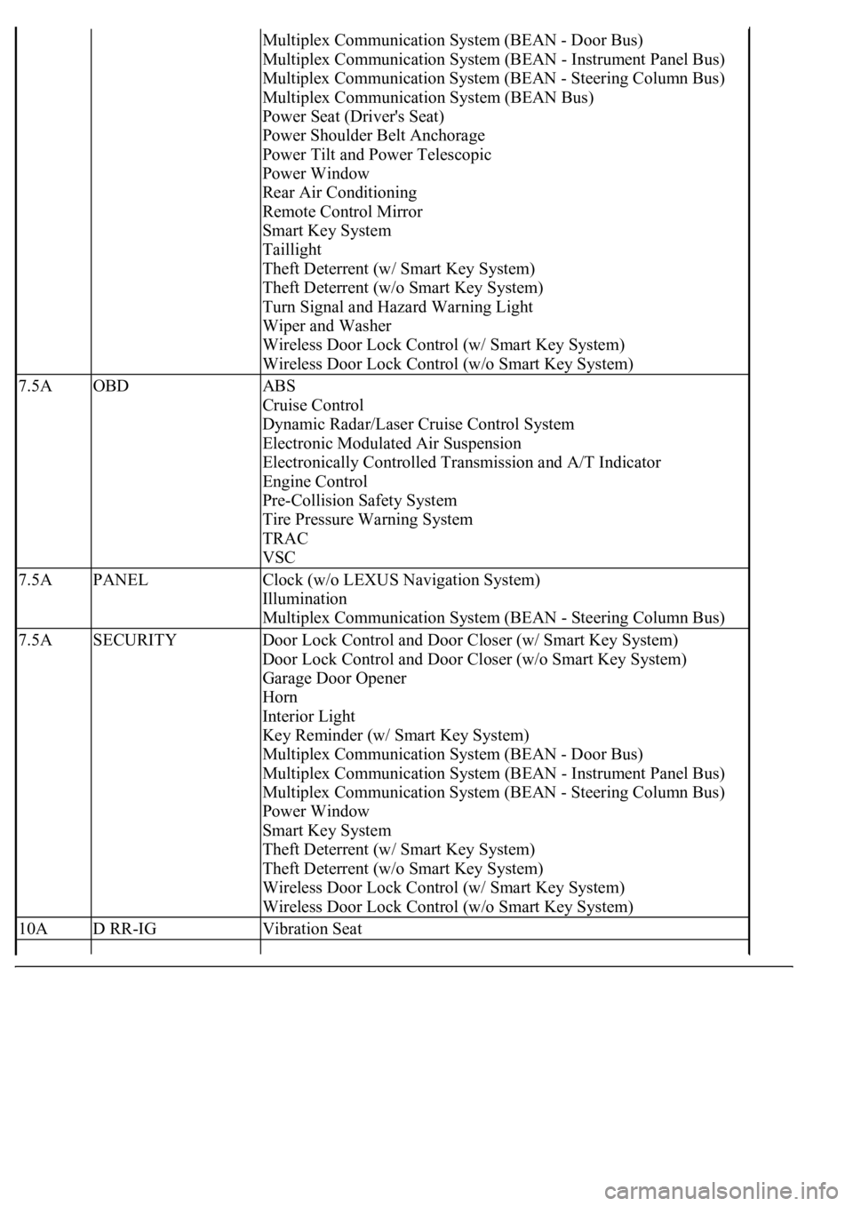
Multiplex Communication System (BEAN - Door Bus)
Multiplex Communication System (BEAN - Instrument Panel Bus)
Multiplex Communication System (BEAN - Steering Column Bus)
Multiplex Communication System (BEAN Bus)
Power Seat (Driver's Seat)
Power Shoulder Belt Anchorage
Power Tilt and Power Telescopic
Power Window
Rear Air Conditioning
Remote Control Mirror
Smart Key System
Taillight
Theft Deterrent (w/ Smart Key System)
Theft Deterrent (w/o Smart Key System)
Turn Signal and Hazard Warning Light
Wiper and Washer
Wireless Door Lock Control (w/ Smart Key System)
Wireless Door Lock Control (w/o Smart Key System)
7.5AOBDABS
Cruise Control
Dynamic Radar/Laser Cruise Control System
Electronic Modulated Air Suspension
Electronically Controlled Transmission and A/T Indicator
Engine Control
Pre-Collision Safety System
Tire Pressure Warning System
TRAC
VSC
7.5APANELClock (w/o LEXUS Navigation System)
Illumination
Multiplex Communication System (BEAN - Steering Column Bus)
7.5ASECURITYDoor Lock Control and Door Closer (w/ Smart Key System)
Door Lock Control and Door Closer (w/o Smart Key System)
Garage Door Opener
Horn
Interior Light
Key Reminder (w/ Smart Key System)
Multiplex Communication System (BEAN - Door Bus)
Multiplex Communication System (BEAN - Instrument Panel Bus)
Multiplex Communication System (BEAN - Steering Column Bus)
Power Window
Smart Key System
Theft Deterrent (w/ Smart Key System)
Theft Deterrent (w/o Smart Key System)
Wireless Door Lock Control (w/ Smart Key System)
Wireless Door Lock Control (w/o Smart Key System)
10AD RR-IGVibration Seat
Page 4277 of 4500
Fig. 89: Disconnecting Liquid Tube Sub-Assy A
Courtesy of TOYOTA MOTOR SALES, U.S.A., INC.
7.REMOVE HIGH PITCHED HORN ASSY (See REPLACEMENT
)
8.REMOVE LOW PITCHED HORN ASSY (See REPLACEMENT
)
9.REMOVE SMOG VENTILATION SENSOR
a. Disconnect the connector.
b. Remove the bolt and smog ventilation sensor.
Page 4321 of 4500
LOCATION
Fig. 1: Identifying Horn System Components And Replacements Location
Courtesy of TOYOTA MOTOR SALES, U.S.A., INC.
Page 4322 of 4500
SYSTEM DIAGRAM
Fig. 2: Identifying Horn System Diagram
Courtesy of TOYOTA MOTOR SALES, U.S.A., INC.
PROBLEM SYMPTOMS TABLE
Fig. 3: Problem Symptoms Table
Courtesy of TOYOTA MOTOR SALES, U.S.A., INC.
INSPECTION
1.INSPECT FUSE (HORN)