Page 722 of 4500

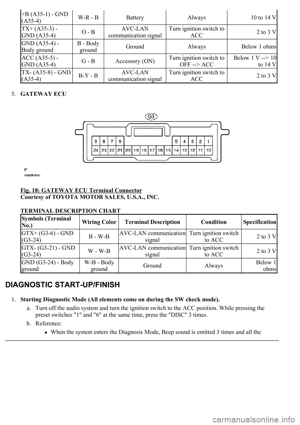
5.GATEWAY ECU
Fig. 18: GATEWAY ECU Terminal Connector
Courtesy of TOYOTA MOTOR SALES, U.S.A., INC.
TERMINAL DESCRIPTION CHART
1.Starting Diagnostic Mode (All elements come on during the SW check mode).
a. Turn off the audio system and turn the ignition switch to the ACC position. While pressing the
preset switches "1" and "6" at the same time, press the "DISC" 3 times.
b. Reference:
<003a004b0048005100030057004b004800030056005c0056005700480050000300480051005700480055005600030057004b004800030027004c0044004a005100520056004c005600030030005200470048000f0003002500480048005300030056005200
58005100470003004c0056000300480050004c005700570048[d 3 times and all the
+B (A35-1) - GND
(A35-4)W-R - BBatteryAlways10 to 14 V
TX+ (A35-3) -
GND (A35-4)O - BAVC-LAN
communication signalTurn ignition switch to
ACC2 to 3 V
GND (A35-4) -
Body groundB - Body
groundGroundAlwaysBelow 1 ohms
ACC (A35-5) -
GND (A35-4)G - BAccessory (ON)Turn ignition switch to
OFF --> ACCBelow 1 V --> 10
to 14 V
TX- (A35-8) - GND
(A35-4)B-Y - BAVC-LAN
communication signalTurn ignition switch to
ACC2 to 3 V
Symbols (Terminal
No.)Wiring ColorTerminal DescriptionConditionSpecification
GTX+ (G3-6) - GND
(G3-24)B - W-BAVC-LAN communication
signalTurn ignition switch
to ACC2 to 3 V
GTX- (G3-21) - GND
(G3-24)W - W-BAVC-LAN communication
signalTurn ignition switch
to ACC2 to 3 V
GND (G3-24) - Body
groundW-B - Body
groundGroundAlwaysBelow 1
ohms
Page 726 of 4500
a. With "CHEC" or "ECHN" being displayed, press the preset switch "2" to go to the detailed
information mode.
b. Press the "SEEK TRACK" switch to display the "System check result (SYS)" and "Diagnostic
memory response (CODE)".
Fig. 21: Identifying Seek Track Switch To Display
Courtesy of TOYOTA MOTOR SALES, U.S.A., INC.
Page 728 of 4500

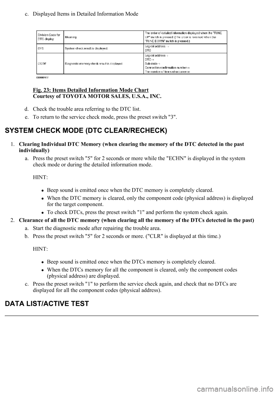
c. Displayed Items in Detailed Information Mode
Fig. 23: Items Detailed Information Mode Chart
Courtesy of TOYOTA MOTOR SALES, U.S.A., INC.
d. Check the trouble area referring to the DTC list.
e. To return to the service check mode, press the preset switch "3".
1.Clearing Individual DTC Memory (when clearing the memory of the DTC detected in the past
individually)
a. Press the preset switch "5" for 2 seconds or more while the "ECHN" is displayed in the system
check mode or during the detailed information mode.
HINT:
Beep sound is emitted once when the DTC memory is completely cleared.
When the DTC memory is cleared, only the component code (physical address) is displayed
for the target component.
To check DTCs, press the preset switch "1" and perform the system check again.
2.<0026004f004800440055004400510046004800030052004900030044004f004f00030057004b00480003002700370026000300500048005000520055005c0003000b005a004b0048005100030046004f004800440055004c0051004a00030044004f004f00
030057004b0048000300500048005000520055005c00030052[f the DTCs detected in the past)
a. Start the diagnostic mode after repairing the trouble area.
b. Press the preset switch "5" for 2 seconds or more. ("CLR" is displayed at this time.)
HINT:
Beep sound is emitted once when the DTCs memory is completely cleared.
When the DTCs memory for all the component is cleared, only the component codes
(physical address) are displayed.
c. Press the preset switch "1" to perform the service check again, and check that no DTCs are
displayed for all the component codes (physical address).
Page 873 of 4500
Fig. 54: Installing Exhaust Pipe No.1 Support Bracket Sub-Assy With 2 Bolts
Courtesy of TOYOTA MOTOR SALES, U.S.A., INC.
49.CONNECT BATTERY NEGATIVE TERMINAL
50.ADJUST SHIFT LEVER POSITION (SEE ADJUSTMENT
)
51.INSPECT SHIFT LEVER POSITION (SEE ADJUSTMENT
)
52.INSTALL PROPELLER W/CENTER BEARING SHAFT ASSY (SEE OVERHAUL
)
53.INSTALL FRONT FLOOR HEAT INSULATOR NO.1 (SEE OVERHAUL
)
54.INSTALL EXHAUST PIPE ASSY (SEE REPLACEMENT
)
55.INSTALL FRONT FLOOR BRACE CENTER (SEE REPLACEMENT
)
56.ADD AUTOMATIC TRANSMISSION FLUID (SEE ADJUSTMENT
)
Fluid type: ATF WS
Capacity: 1.7 liters (1.8 US qts, 1.5 lmp. qts)
57.INSTALL ENGINE UNDER COVER NO.2
58.INSTALL ENGINE UNDER COVER NO.1
59.RESET MEMORY (SEE INITIALIZATION
)
60.PERFORM INITIALIZATION (SEE INITIALIZATION
)
Page 893 of 4500
Fig. 72: Installing Oil Pan With 20 Bolts To Transmission Case
Courtesy of TOYOTA MOTOR SALES, U.S.A., INC.
11.CONNECT BATTERY NEGATIVE TERMINAL
12.ADD AUTOMATIC TRANSMISSION FLUID (SEE ADJUSTMENT
)
Fluid type: ATF WS
Capacity: 4.3 liters (4.5 US qts, 3.8 Imp.qts)
13.RESET MEMORY (SEE INITIALIZATION
)
14.PERFORM INITIALIZATION (SEE INITIALIZATION
)
REPLACEMENT
<00380056004c0051004a00030044000300550044005d0052005500030045004f00440047004800030044005100470003004a00440056004e0048005700030056004600550044005300480055000f000300550048005000520059004800030044004f004f00
030057004b004800030052004f004700030029002c0033002a[ material from the gasket surfaces.
Thoroughly clean all components to remove any loose material.
Page 912 of 4500
Fig. 90: Installing Oil Pan With 20 Bolts To Transmission Case
Courtesy of TOYOTA MOTOR SALES, U.S.A., INC.
11.CONNECT BATTERY NEGATIVE TERMINAL
12.ADD AUTOMATIC TRANSMISSION FLUID (SEE ADJUSTMENT
)
Fluid type: ATF WS
Capacity: 4.3 liters (4.5 US qts, 3.8 Imp.qts)
13.RESET MEMORY (SEE INITIALIZATION
)
14.PERFORM INITIALIZATION (SEE INITIALIZATION
)
REPLACEMENT
1.REMOVE INSTRUMENT PANEL UNDER COVER SUB-ASSY NO.2 (SEE REPLACEMENT
)
2.REMOVE INSTRUMENT PANEL GARNISH SUB-ASSY LH (SEE REPLACEMENT
)
3.REMOVE INSTRUMENT PANEL FINISH PANEL (SEE REPLACEMENT
)
4.REMOVE INSTRUMENT PANEL UNDER COVER SUB-ASSY NO.1 (SEE REPLACEMENT
)
5.REMOVE SWITCH BRACE HOLE COVER (SEE REPLACEMENT
)
Page 1749 of 4500
Courtesy of TOYOTA MOTOR SALES, U.S.A., INC.
Fig. 15: Warning Area Flow Chart (2 Of 2)
Courtesy of TOYOTA MOTOR SALES, U.S.A., INC.
Warning process:
The warning items can be scrolled automatically. (Unable to switch manually)
When any malfunction in the framed items is detected, a warning buzzer (a single sound)
sounds. It sounds only when the malfunction occurs for the first time. The item is displayed
along with the buzzer sounding.
The most current warning item is displayed first.
When two or more warning occur, they are displayed in turn at an interval of 2 seconds.
When a warnings occurs, the item is displayed for 6 seconds only the first time.
Smart Key System:
The buzzer in the smart key system is controlled by a signal from the security ECU.
HINT:
The buzzer sounds continuously if the item "Shift to P range" is displayed.
Oil Maintenance Display:
The items are displayed in accordance with the distance after reset (see ON-VEHICLE
Page 1755 of 4500
Fig. 19: Identifying Zone Setting Number
Courtesy of TOYOTA MOTOR SALES, U.S.A., INC.
8.CALIBRATION SETTING MODE
a. Keep pressing the "RESET" for 6 sec. after selection of the compass display mode will activate the
calibration setting mode.
b. Drive the vehicle at a slow speed of 8 km/h (5 MPH) or less in the circular direction.
c. Driving round the circle 1 to 3 times will display the azimuthal direction on the display, completing
the calibration.
d. To finish the calibration mode, press the DISP2 switch long when the calibration is finished or
during the calibration.
HINT: