2003 JEEP GRAND CHEROKEE stall
[x] Cancel search: stallPage 1595 of 2199
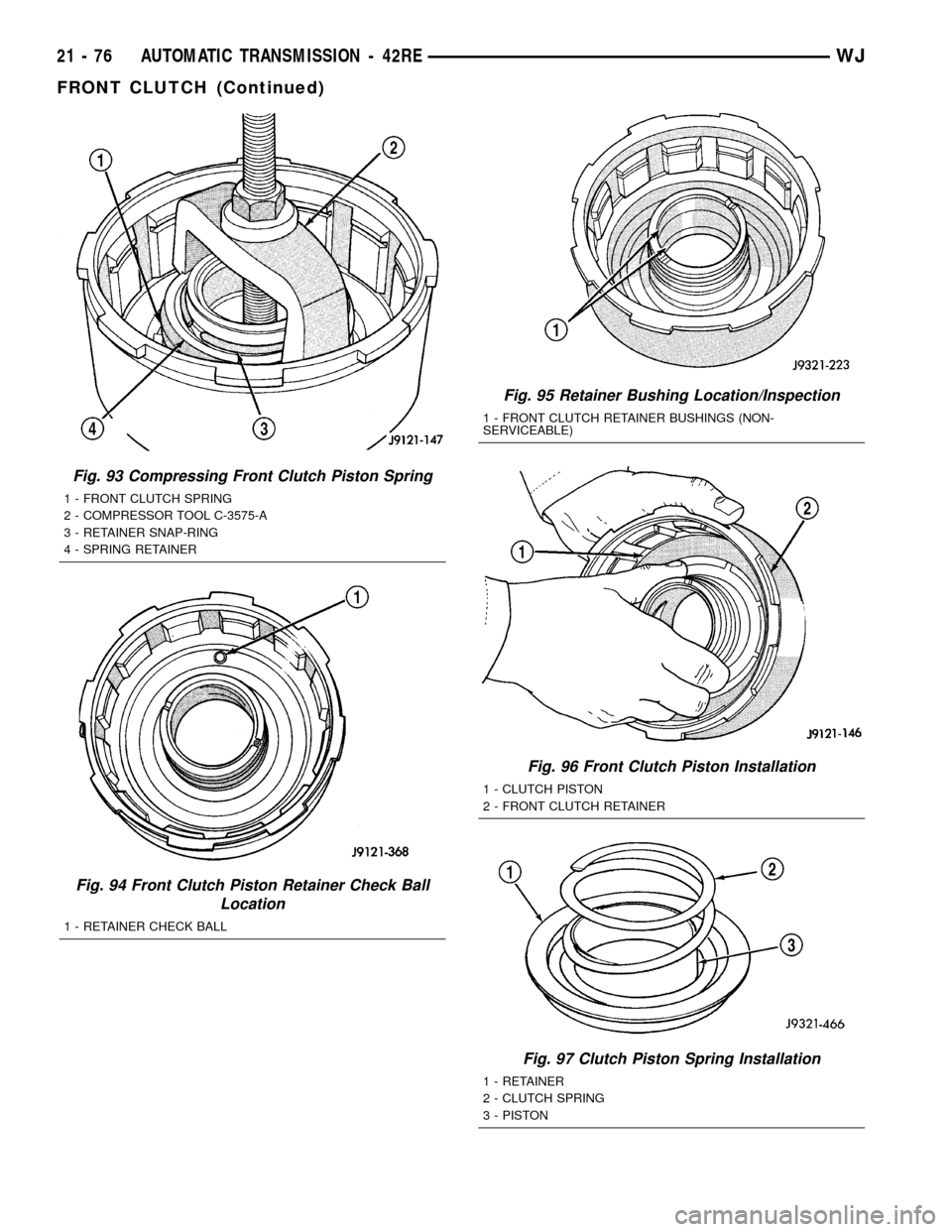
Fig. 93 Compressing Front Clutch Piston Spring
1 - FRONT CLUTCH SPRING
2 - COMPRESSOR TOOL C-3575-A
3 - RETAINER SNAP-RING
4 - SPRING RETAINER
Fig. 94 Front Clutch Piston Retainer Check Ball
Location
1 - RETAINER CHECK BALL
Fig. 95 Retainer Bushing Location/Inspection
1 - FRONT CLUTCH RETAINER BUSHINGS (NON-
SERVICEABLE)
Fig. 96 Front Clutch Piston Installation
1 - CLUTCH PISTON
2 - FRONT CLUTCH RETAINER
Fig. 97 Clutch Piston Spring Installation
1 - RETAINER
2 - CLUTCH SPRING
3 - PISTON
21 - 76 AUTOMATIC TRANSMISSION - 42REWJ
FRONT CLUTCH (Continued)
Page 1596 of 2199
FRONT SERVO
DESCRIPTION
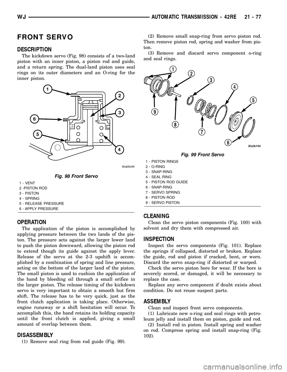
The kickdown servo (Fig. 98) consists of a two-land
piston with an inner piston, a piston rod and guide,
and a return spring. The dual-land piston uses seal
rings on its outer diameters and an O-ring for the
inner piston.
OPERATION
The application of the piston is accomplished by
applying pressure between the two lands of the pis-
ton. The pressure acts against the larger lower land
to push the piston downward, allowing the piston rod
to extend though its guide against the apply lever.
Release of the servo at the 2-3 upshift is accom-
plished by a combination of spring and line pressure,
acting on the bottom of the larger land of the piston.
The small piston is used to cushion the application of
the band by bleeding oil through a small orifice in
the larger piston. The release timing of the kickdown
servo is very important to obtain a smooth but firm
shift. The release has to be very quick, just as the
front clutch application is taking place. Otherwise,
engine runaway or a shift hesitation will occur. To
accomplish this, the band retains its holding capacity
until the front clutch is applied, giving a small
amount of overlap between them.
DISASSEMBLY
(1) Remove seal ring from rod guide (Fig. 99).(2) Remove small snap-ring from servo piston rod.
Then remove piston rod, spring and washer from pis-
ton.
(3) Remove and discard servo component o-ring
and seal rings.
CLEANING
Clean the servo piston components (Fig. 100) with
solvent and dry them with compressed air.
INSPECTION
Inspect the servo components (Fig. 101). Replace
the springs if collapsed, distorted or broken. Replace
the guide, rod and piston if cracked, bent, or worn.
Discard the servo snap-ring if distorted or warped.
Check the servo piston bore for wear. If the bore is
severely scored, or damaged, it will be necessary to
replace the case.
Replace any servo component if doubt exists about
condition. Do not reuse suspect parts.
ASSEMBLY
Clean and inspect front servo components.
(1) Lubricate new o-ring and seal rings with petro-
leum jelly and install them on piston, guide and rod.
(2) Install rod in piston. Install spring and washer
on rod. Compress spring and install snap-ring (Fig.
102).
Fig. 98 Front Servo
1 - VENT
2 -PISTON ROD
3 - PISTON
4 - SPRING
5 - RELEASE PRESSURE
6 - APPLY PRESSURE
Fig. 99 Front Servo
1 - PISTON RINGS
2 - O-RING
3 - SNAP-RING
4 - SEAL RING
5 - PISTON ROD GUIDE
6 - SNAP-RING
7 - SERVO SPRING
8 - PISTON ROD
9 - SERVO PISTON
WJAUTOMATIC TRANSMISSION - 42RE 21 - 77
Page 1598 of 2199
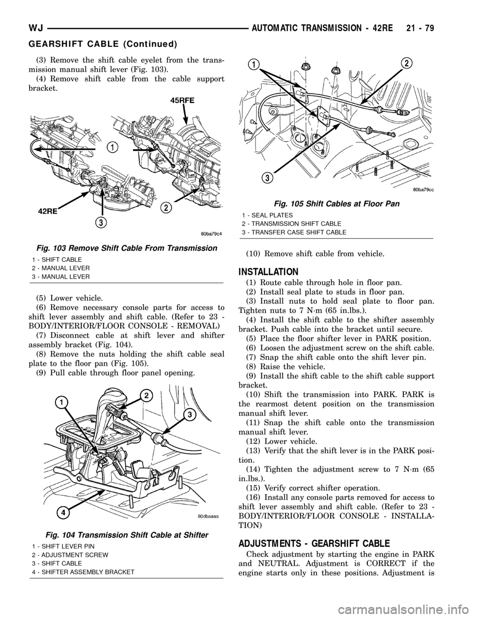
(3) Remove the shift cable eyelet from the trans-
mission manual shift lever (Fig. 103).
(4) Remove shift cable from the cable support
bracket.
(5) Lower vehicle.
(6) Remove necessary console parts for access to
shift lever assembly and shift cable. (Refer to 23 -
BODY/INTERIOR/FLOOR CONSOLE - REMOVAL)
(7) Disconnect cable at shift lever and shifter
assembly bracket (Fig. 104).
(8) Remove the nuts holding the shift cable seal
plate to the floor pan (Fig. 105).
(9) Pull cable through floor panel opening.(10) Remove shift cable from vehicle.
INSTALLATION
(1) Route cable through hole in floor pan.
(2) Install seal plate to studs in floor pan.
(3) Install nuts to hold seal plate to floor pan.
Tighten nuts to 7 N´m (65 in.lbs.).
(4) Install the shift cable to the shifter assembly
bracket. Push cable into the bracket until secure.
(5) Place the floor shifter lever in PARK position.
(6) Loosen the adjustment screw on the shift cable.
(7) Snap the shift cable onto the shift lever pin.
(8) Raise the vehicle.
(9) Install the shift cable to the shift cable support
bracket.
(10) Shift the transmission into PARK. PARK is
the rearmost detent position on the transmission
manual shift lever.
(11) Snap the shift cable onto the transmission
manual shift lever.
(12) Lower vehicle.
(13) Verify that the shift lever is in the PARK posi-
tion.
(14) Tighten the adjustment screw to 7 N´m (65
in.lbs.).
(15) Verify correct shifter operation.
(16) Install any console parts removed for access to
shift lever assembly and shift cable. (Refer to 23 -
BODY/INTERIOR/FLOOR CONSOLE - INSTALLA-
TION)
ADJUSTMENTS - GEARSHIFT CABLE
Check adjustment by starting the engine in PARK
and NEUTRAL. Adjustment is CORRECT if the
engine starts only in these positions. Adjustment is
Fig. 103 Remove Shift Cable From Transmission
1 - SHIFT CABLE
2 - MANUAL LEVER
3 - MANUAL LEVER
Fig. 104 Transmission Shift Cable at Shifter
1 - SHIFT LEVER PIN
2 - ADJUSTMENT SCREW
3 - SHIFT CABLE
4 - SHIFTER ASSEMBLY BRACKET
Fig. 105 Shift Cables at Floor Pan
1 - SEAL PLATES
2 - TRANSMISSION SHIFT CABLE
3 - TRANSFER CASE SHIFT CABLE
WJAUTOMATIC TRANSMISSION - 42RE 21 - 79
GEARSHIFT CABLE (Continued)
Page 1599 of 2199
INCORRECT if the engine starts in one but not both
positions. If the engine starts in any position other
than PARK or NEUTRAL, or if the engine will not
start at all, the park/neutral position switch or TRS
may be faulty.
(1) Shift transmission into PARK.
(2) Remove floor console as necessary for access to
the shift cable adjustment. (Refer to 23 - BODY/IN-
TERIOR/FLOOR CONSOLE - REMOVAL)
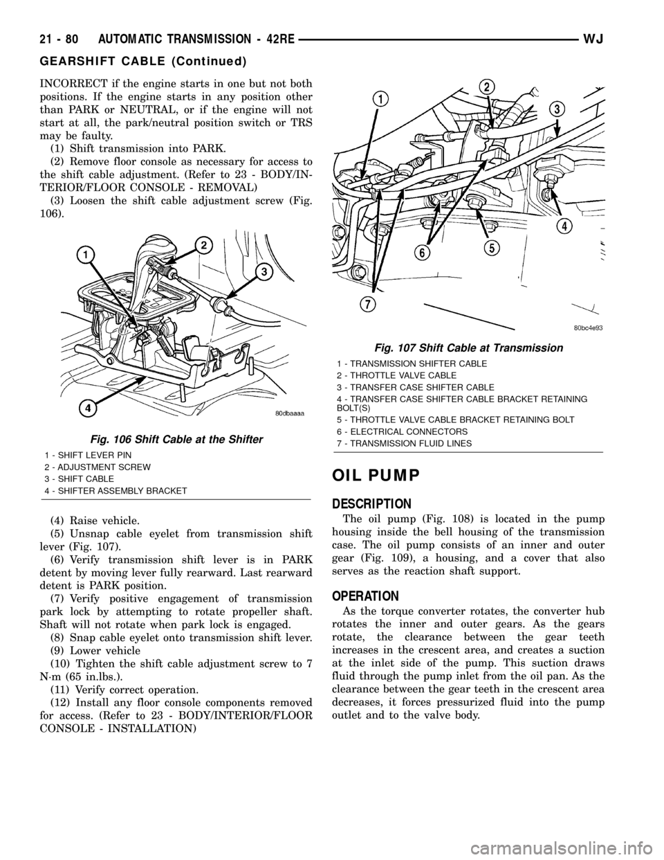
(3) Loosen the shift cable adjustment screw (Fig.
106).
(4) Raise vehicle.
(5) Unsnap cable eyelet from transmission shift
lever (Fig. 107).
(6) Verify transmission shift lever is in PARK
detent by moving lever fully rearward. Last rearward
detent is PARK position.
(7) Verify positive engagement of transmission
park lock by attempting to rotate propeller shaft.
Shaft will not rotate when park lock is engaged.
(8) Snap cable eyelet onto transmission shift lever.
(9) Lower vehicle
(10) Tighten the shift cable adjustment screw to 7
N´m (65 in.lbs.).
(11) Verify correct operation.
(12) Install any floor console components removed
for access. (Refer to 23 - BODY/INTERIOR/FLOOR
CONSOLE - INSTALLATION)
OIL PUMP
DESCRIPTION
The oil pump (Fig. 108) is located in the pump
housing inside the bell housing of the transmission
case. The oil pump consists of an inner and outer
gear (Fig. 109), a housing, and a cover that also
serves as the reaction shaft support.
OPERATION
As the torque converter rotates, the converter hub
rotates the inner and outer gears. As the gears
rotate, the clearance between the gear teeth
increases in the crescent area, and creates a suction
at the inlet side of the pump. This suction draws
fluid through the pump inlet from the oil pan. As the
clearance between the gear teeth in the crescent area
decreases, it forces pressurized fluid into the pump
outlet and to the valve body.
Fig. 106 Shift Cable at the Shifter
1 - SHIFT LEVER PIN
2 - ADJUSTMENT SCREW
3 - SHIFT CABLE
4 - SHIFTER ASSEMBLY BRACKET
Fig. 107 Shift Cable at Transmission
1 - TRANSMISSION SHIFTER CABLE
2 - THROTTLE VALVE CABLE
3 - TRANSFER CASE SHIFTER CABLE
4 - TRANSFER CASE SHIFTER CABLE BRACKET RETAINING
BOLT(S)
5 - THROTTLE VALVE CABLE BRACKET RETAINING BOLT
6 - ELECTRICAL CONNECTORS
7 - TRANSMISSION FLUID LINES
21 - 80 AUTOMATIC TRANSMISSION - 42REWJ
GEARSHIFT CABLE (Continued)
Page 1601 of 2199
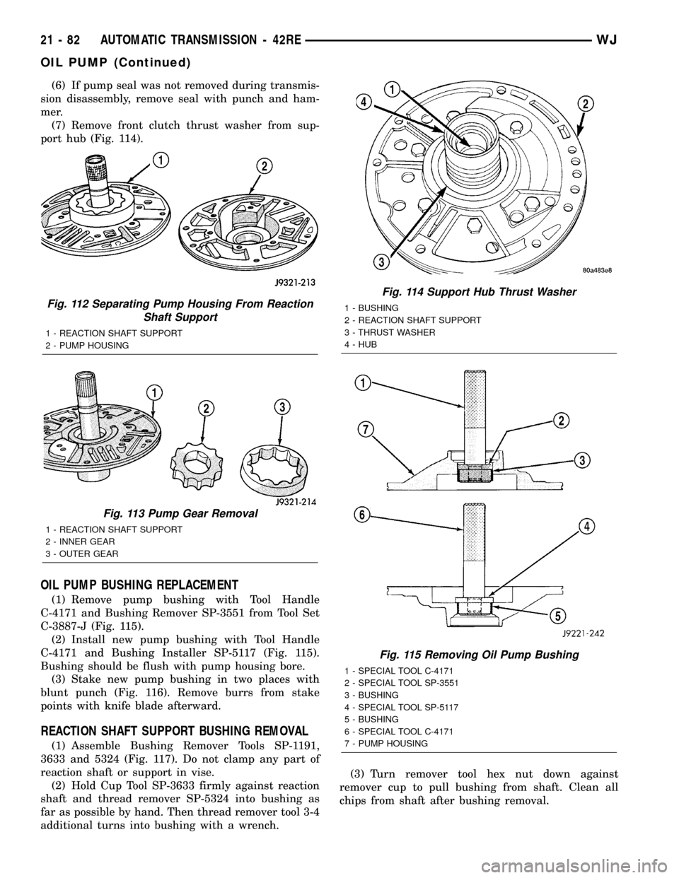
(6) If pump seal was not removed during transmis-
sion disassembly, remove seal with punch and ham-
mer.
(7) Remove front clutch thrust washer from sup-
port hub (Fig. 114).
OIL PUMP BUSHING REPLACEMENT
(1) Remove pump bushing with Tool Handle
C-4171 and Bushing Remover SP-3551 from Tool Set
C-3887-J (Fig. 115).
(2) Install new pump bushing with Tool Handle
C-4171 and Bushing Installer SP-5117 (Fig. 115).
Bushing should be flush with pump housing bore.
(3) Stake new pump bushing in two places with
blunt punch (Fig. 116). Remove burrs from stake
points with knife blade afterward.
REACTION SHAFT SUPPORT BUSHING REMOVAL
(1) Assemble Bushing Remover Tools SP-1191,
3633 and 5324 (Fig. 117). Do not clamp any part of
reaction shaft or support in vise.
(2) Hold Cup Tool SP-3633 firmly against reaction
shaft and thread remover SP-5324 into bushing as
far as possible by hand. Then thread remover tool 3-4
additional turns into bushing with a wrench.(3) Turn remover tool hex nut down against
remover cup to pull bushing from shaft. Clean all
chips from shaft after bushing removal.
Fig. 112 Separating Pump Housing From Reaction
Shaft Support
1 - REACTION SHAFT SUPPORT
2 - PUMP HOUSING
Fig. 113 Pump Gear Removal
1 - REACTION SHAFT SUPPORT
2 - INNER GEAR
3 - OUTER GEAR
Fig. 114 Support Hub Thrust Washer
1 - BUSHING
2 - REACTION SHAFT SUPPORT
3 - THRUST WASHER
4 - HUB
Fig. 115 Removing Oil Pump Bushing
1 - SPECIAL TOOL C-4171
2 - SPECIAL TOOL SP-3551
3 - BUSHING
4 - SPECIAL TOOL SP-5117
5 - BUSHING
6 - SPECIAL TOOL C-4171
7 - PUMP HOUSING
21 - 82 AUTOMATIC TRANSMISSION - 42REWJ
OIL PUMP (Continued)
Page 1602 of 2199
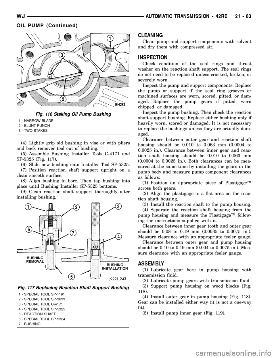
(4) Lightly grip old bushing in vise or with pliers
and back remover tool out of bushing.
(5) Assemble Bushing Installer Tools C-4171 and
SP-5325 (Fig. 117).
(6) Slide new bushing onto Installer Tool SP-5325.
(7) Position reaction shaft support upright on a
clean smooth surface.
(8) Align bushing in bore. Then tap bushing into
place until Bushing Installer SP-5325 bottoms.
(9) Clean reaction shaft support thoroughly after
installing bushing.
CLEANING
Clean pump and support components with solvent
and dry them with compressed air.
INSPECTION
Check condition of the seal rings and thrust
washer on the reaction shaft support. The seal rings
do not need to be replaced unless cracked, broken, or
severely worn.
Inspect the pump and support components. Replace
the pump or support if the seal ring grooves or
machined surfaces are worn, scored, pitted, or dam-
aged. Replace the pump gears if pitted, worn
chipped, or damaged.
Inspect the pump bushing. Then check the reaction
shaft support bushing. Replace either bushing only if
heavily worn, scored or damaged. It is not necessary
to replace the bushings unless they are actually dam-
aged.
Clearance between outer gear and reaction shaft
housing should be 0.010 to 0.063 mm (0.0004 to
0.0025 in.). Clearance between inner gear and reac-
tion shaft housing should be 0.010 to 0.063 mm
(0.0004 to 0.0025 in.). Both clearances can be mea-
sured at the same time by installing the gears in the
pump body and measure pump component clearances
as follows:
(1) Position an appropriate piece of PlastigageŸ
across both gears.
(2) Align the plastigage to a flat area on the reac-
tion shaft housing.
(3) Install the reaction shaft to the pump housing.
(4) Separate the reaction shaft housing from the
pump housing and measure the PlastigageŸ follow-
ing the instructions supplied with it.
Clearance between inner gear tooth and outer gear
should be 0.08 to 0.19 mm (0.0035 to 0.0075 in.).
Measure clearance with an appropriate feeler gauge.
Clearance between outer gear and pump housing
should be 0.10 to 0.19 mm (0.004 to 0.0075 in.). Mea-
sure clearance with an appropriate feeler gauge.
ASSEMBLY
(1) Lubricate gear bore in pump housing with
transmission fluid.
(2) Lubricate pump gears with transmission fluid.
(3) Support pump housing on wood blocks (Fig.
118).
(4) Install outer gear in pump housing (Fig. 118).
Gear can be installed either way (it is not a one-way
fit).
(5) Install pump inner gear (Fig. 119).
Fig. 116 Staking Oil Pump Bushing
1 - NARROW BLADE
2 - BLUNT PUNCH
3 - TWO STAKES
Fig. 117 Replacing Reaction Shaft Support Bushing
1 - SPECIAL TOOL SP-1191
2 - SPECIAL TOOL SP-3633
3 - SPECIAL TOOL C-4171
4 - SPECIAL TOOL SP-5325
5 - REACTION SHAFT
6 - SPECIAL TOOL SP-5324
7 - BUSHING
WJAUTOMATIC TRANSMISSION - 42RE 21 - 83
OIL PUMP (Continued)
Page 1603 of 2199
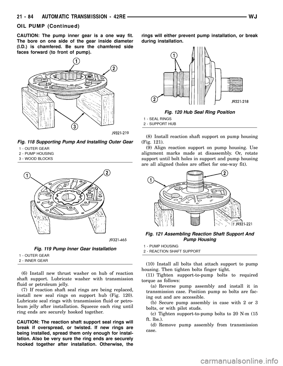
CAUTION: The pump inner gear is a one way fit.
The bore on one side of the gear inside diameter
(I.D.) is chamfered. Be sure the chamfered side
faces forward (to front of pump).
(6) Install new thrust washer on hub of reaction
shaft support. Lubricate washer with transmission
fluid or petroleum jelly.
(7) If reaction shaft seal rings are being replaced,
install new seal rings on support hub (Fig. 120).
Lubricate seal rings with transmission fluid or petro-
leum jelly after installation. Squeeze each ring until
ring ends are securely hooked together.
CAUTION: The reaction shaft support seal rings will
break if overspread, or twisted. If new rings are
being installed, spread them only enough for instal-
lation. Also be very sure the ring ends are securely
hooked together after installation. Otherwise, therings will either prevent pump installation, or break
during installation.
(8) Install reaction shaft support on pump housing
(Fig. 121).
(9) Align reaction support on pump housing. Use
alignment marks made at disassembly. Or, rotate
support until bolt holes in support and pump housing
are all aligned (holes are offset for one-way fit).
(10) Install all bolts that attach support to pump
housing. Then tighten bolts finger tight.
(11) Tighten support-to-pump bolts to required
torque as follows:
(a) Reverse pump assembly and install it in
transmission case. Position pump so bolts are fac-
ing out and are accessible.
(b) Secure pump assembly in case with 2 or 3
bolts, or with pilot studs.
(c) Tighten support-to-pump bolts to 20 N´m (15
ft. lbs.).
(d) Remove pump assembly from transmission
case.
Fig. 118 Supporting Pump And Installing Outer Gear
1 - OUTER GEAR
2 - PUMP HOUSING
3 - WOOD BLOCKS
Fig. 119 Pump Inner Gear Installation
1 - OUTER GEAR
2 - INNER GEAR
Fig. 120 Hub Seal Ring Position
1 - SEAL RINGS
2 - SUPPORT HUB
Fig. 121 Assembling Reaction Shaft Support And
Pump Housing
1 - PUMP HOUSING
2 - REACTION SHAFT SUPPORT
21 - 84 AUTOMATIC TRANSMISSION - 42REWJ
OIL PUMP (Continued)
Page 1604 of 2199
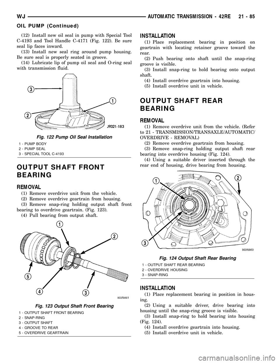
(12) Install new oil seal in pump with Special Tool
C-4193 and Tool Handle C-4171 (Fig. 122). Be sure
seal lip faces inward.
(13) Install new seal ring around pump housing.
Be sure seal is properly seated in groove.
(14) Lubricate lip of pump oil seal and O-ring seal
with transmission fluid.
OUTPUT SHAFT FRONT
BEARING
REMOVAL
(1) Remove overdrive unit from the vehicle.
(2) Remove overdrive geartrain from housing.
(3) Remove snap-ring holding output shaft front
bearing to overdrive geartrain. (Fig. 123).
(4) Pull bearing from output shaft.
INSTALLATION
(1) Place replacement bearing in position on
geartrain with locating retainer groove toward the
rear.
(2) Push bearing onto shaft until the snap-ring
groove is visible.
(3) Install snap-ring to hold bearing onto output
shaft.
(4) Install overdrive geartrain into housing.
(5) Install overdrive unit in vehicle.
OUTPUT SHAFT REAR
BEARING
REMOVAL
(1) Remove overdrive unit from the vehicle. (Refer
to 21 - TRANSMISSION/TRANSAXLE/AUTOMATIC/
OVERDRIVE - REMOVAL)
(2) Remove overdrive geartrain from housing.
(3) Remove snap-ring holding output shaft rear
bearing into overdrive housing (Fig. 124).
(4) Using a suitable driver inserted through the
rear end of housing, drive bearing from housing.
INSTALLATION
(1) Place replacement bearing in position in hous-
ing.
(2) Using a suitable driver, drive bearing into
housing until the snap-ring groove is visible.
(3) Install snap-ring to hold bearing into housing
(Fig. 124).
(4) Install overdrive geartrain into housing.
(5) Install overdrive unit in vehicle.
Fig. 122 Pump Oil Seal Installation
1 - PUMP BODY
2 - PUMP SEAL
3 - SPECIAL TOOL C-4193
Fig. 123 Output Shaft Front Bearing
1 - OUTPUT SHAFT FRONT BEARING
2 - SNAP-RING
3 - OUTPUT SHAFT
4 - GROOVE TO REAR
5 - OVERDRIVE GEARTRAIN
Fig. 124 Output Shaft Rear Bearing
1 - OUTPUT SHAFT REAR BEARING
2 - OVERDRIVE HOUSING
3 - SNAP-RING
WJAUTOMATIC TRANSMISSION - 42RE 21 - 85
OIL PUMP (Continued)