2003 JEEP GRAND CHEROKEE stall
[x] Cancel search: stallPage 2184 of 2199

INSTALLATION - FIXED ORIFICE FITTING
When installing fixed orifice fitting, be sure loca-
tions of fixed orifice fitting and air inlet fitting (Fig.
9) have not been inadvertently exchanged. The fixed
orifice fitting is light grey in color and is located at
rearof valve cover. The air inlet fitting is black in
color and is located atfrontof valve cover.
(1) Connect fitting to CCV breather tube.
(2) Return fixed orifice fitting to valve cover grom-
met.
EVAP/PURGE SOLENOID
DESCRIPTION
The duty cycle EVAP canister purge solenoid (DCP)
regulates the rate of vapor flow from the EVAP can-
ister to the intake manifold. The Powertrain Control
Module (PCM) operates the solenoid.
OPERATION
During the cold start warm-up period and the hot
start time delay, the PCM does not energize the sole-
noid. When de-energized, no vapors are purged. The
PCM de-energizes the solenoid during open loop oper-
ation.
The engine enters closed loop operation after it
reaches a specified temperature and the time delay
ends. During closed loop operation, the PCM cycles
(energizes and de-energizes) the solenoid 5 or 10
times per second, depending upon operating condi-
tions. The PCM varies the vapor flow rate by chang-
ing solenoid pulse width. Pulse width is the amount
of time that the solenoid is energized. The PCM
adjusts solenoid pulse width based on engine operat-
ing condition.
REMOVAL
The duty cycle evaporative (EVAP) canister purge
solenoid is located in the engine compartment near
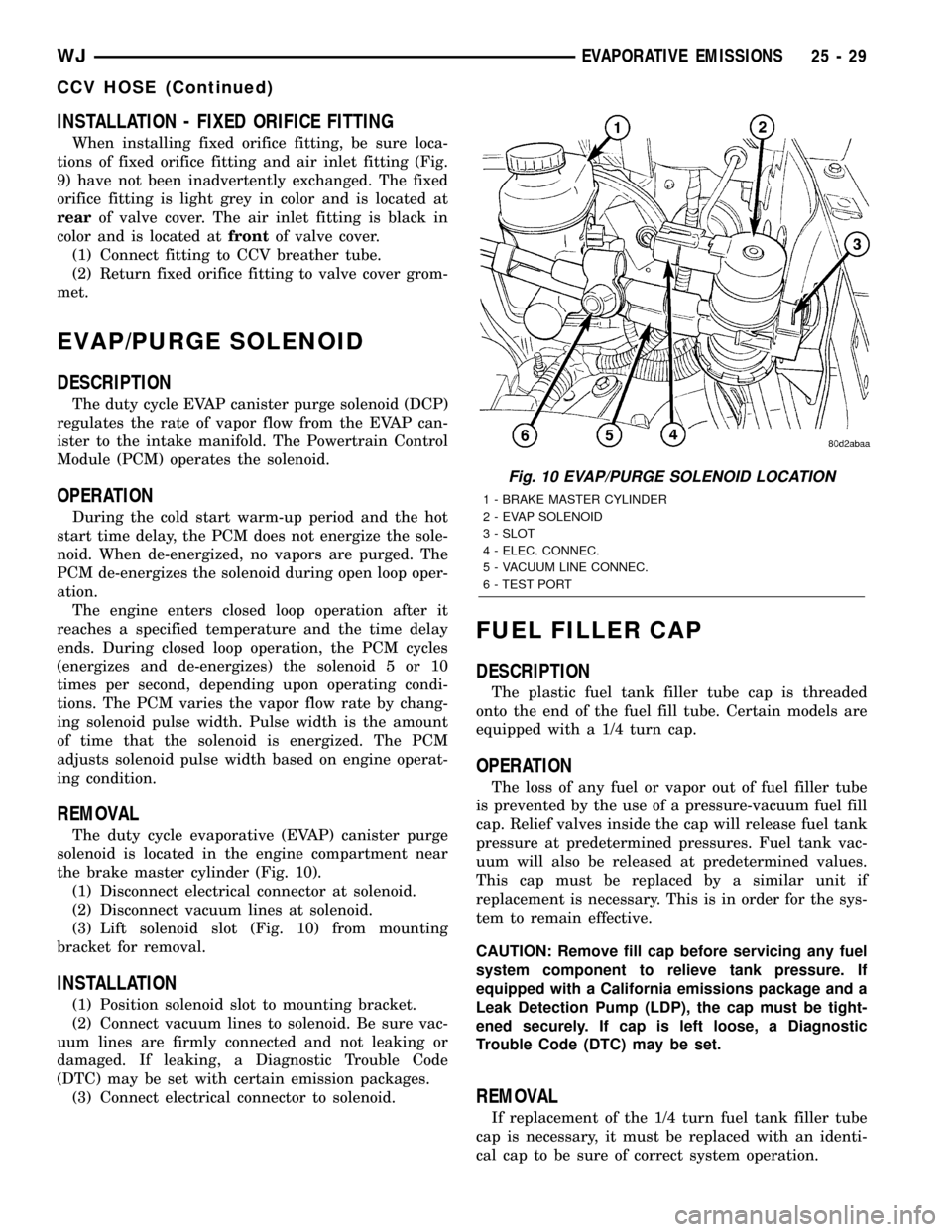
the brake master cylinder (Fig. 10).
(1) Disconnect electrical connector at solenoid.
(2) Disconnect vacuum lines at solenoid.
(3) Lift solenoid slot (Fig. 10) from mounting
bracket for removal.
INSTALLATION
(1) Position solenoid slot to mounting bracket.
(2) Connect vacuum lines to solenoid. Be sure vac-
uum lines are firmly connected and not leaking or
damaged. If leaking, a Diagnostic Trouble Code
(DTC) may be set with certain emission packages.
(3) Connect electrical connector to solenoid.
FUEL FILLER CAP
DESCRIPTION
The plastic fuel tank filler tube cap is threaded
onto the end of the fuel fill tube. Certain models are
equipped with a 1/4 turn cap.
OPERATION
The loss of any fuel or vapor out of fuel filler tube
is prevented by the use of a pressure-vacuum fuel fill
cap. Relief valves inside the cap will release fuel tank
pressure at predetermined pressures. Fuel tank vac-
uum will also be released at predetermined values.
This cap must be replaced by a similar unit if
replacement is necessary. This is in order for the sys-
tem to remain effective.
CAUTION: Remove fill cap before servicing any fuel
system component to relieve tank pressure. If
equipped with a California emissions package and a
Leak Detection Pump (LDP), the cap must be tight-
ened securely. If cap is left loose, a Diagnostic
Trouble Code (DTC) may be set.
REMOVAL
If replacement of the 1/4 turn fuel tank filler tube
cap is necessary, it must be replaced with an identi-
cal cap to be sure of correct system operation.
Fig. 10 EVAP/PURGE SOLENOID LOCATION
1 - BRAKE MASTER CYLINDER
2 - EVAP SOLENOID
3 - SLOT
4 - ELEC. CONNEC.
5 - VACUUM LINE CONNEC.
6 - TEST PORT
WJEVAPORATIVE EMISSIONS 25 - 29
CCV HOSE (Continued)
Page 2188 of 2199

²No engine stall during test.
NOTE: IF BATTERY VOLTAGE DROPS BELOW 10
VOLTS FOR MORE THAN 5 SECONDS DURING
ENGINE CRANKING, THE EVAP LEAK DETECTION
TEST WILL NOT RUN.
NOTE: THE FOLLOWING VALUES ARE APPROXI-
MATE AND VEHICLE SPECIFIC. USE THE VALUES
SEEN IN PRE TEST/MONITOR TEST SCREEN ON
THE DRB IIIT. SEE TSB 25-02-98 FOR MORE
DETAIL.
A DTC will not be set if a one-trip fault is set or if
the MIL is illuminated for any of the following:
²Purge Solenoid Electrical Fault
²All TPS Faults
²All Engine Controller Self Test Faults
²LDP Pressure Switch Fault
²All Cam and/or Crank Sensor Fault
²EGR Solenoid Electrical Fault
²All MAP Sensor Faults
²All Injector Faults
²Ambient/Battery Temperature Sensor Electrical
Faults²Baro Out of Range
²Vehicle Speed Faults
²All Coolant Sensor Faults
²LDP Solenoid Circuit
NOTE: IF BATTERY TEMPERATURE IS NOT WITHIN
RANGE, OR IF THE ENGINE COOLANT TEMPERA-
TURE IS NOT WITHIN A SPECIFIED RANGE OF THE
BATTERY TEMPERATURE, THE PCM WILL NOT
RUN TESTS FOR DTC P1494, P1486, P0442, P0455
AND P0441. THESE TEMPERATURE CALIBRATIONS
MAY BE DIFFERENT BETWEEN MODELS.
SECTION 1 - P1495 Leak Detection Pump
Solenoid Circuit-When the ignition key is turned
to9ON9, the LDP diaphragm should be in the down
position and the LDP reed switch should be closed. If
the EVAP system has residual pressure, the LDP dia-
phragm may be up. This could result in the LDP reed
switch being open when the key is turned to9ON9
and a P1494 fault could be set because the PCM is
expecting the reed switch to be closed.
After the key is turned9ON9, the PCM immedi-
ately tests the LDP solenoid circuit for electrical
faults. If a fault is detected, DTC P1495 will set, the
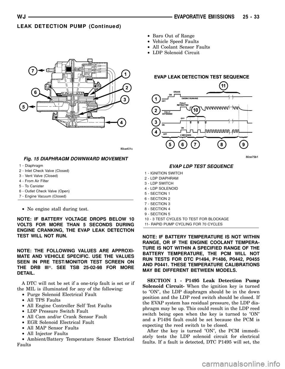
Fig. 15 DIAPHRAGM DOWNWARD MOVEMENT
1 - Diaphragm
2 - Inlet Check Valve (Closed)
3 - Vent Valve (Closed)
4 - From Air Filter
5 - To Canister
6 - Outlet Check Valve (Open)
7 - Engine Vacuum (Closed)EVAP LDP TEST SEQUENCE
1 - IGNITION SWITCH
2 - LDP DIAPHRAM
3 - LDP SWITCH
4 - LDP SOLENOID
5 - SECTION 1
6 - SECTION 2
7 - SECTION 3
8 - SECTION 4
9 - SECTION 5
10 - 3 TEST CYCLES TO TEST FOR BLOCKAGE
11- RAPID PUMP CYCLING FOR 70 CYCLES
WJEVAPORATIVE EMISSIONS 25 - 33
LEAK DETECTION PUMP (Continued)
Page 2190 of 2199

set a temporary fault without turning on the MIL
and continue the leak portion of the test. However,
the PCM will assume that the system is already
pressurized and skip the rapid pump cycles.
Always diagnose leaks, if possible, before discon-
necting connections. Disconnecting connections may
mask a leak condition.
Keep in mind that if the purge solenoid seat is
leaking, it could go undetected since the leak would
end up in the intake manifold. Disconnect the purge
solenoid at the manifold when leak checking. In addi-
tion, a pinched hose fault (P1486) could set if the
purge solenoid does not purge the fuel system prop-
erly (blocked seat). The purge solenoid must vent the
fuel system prior to the LDP system test. If the
purge solenoid cannot properly vent the system the
LDP cannot properly complete the test for P1486 and
this fault can set due to pressure being in the EVAP
system during the test sequence.
Multiple actuation's of the DRB IIItLeak Detec-
tion Pump (LDP) Monitor Test can hide a 0.020 leak
because of excess vapor generation. Additionally, any
source for additional vapor generation can hide a
small leak in the EVAP system. Excess vapor gener-
ation can delay the fall of the LDP diaphragm thus
hiding the small leak. An example of this condition
could be bringing a cold vehicle into a warm shop for
testing or high ambient temperatures.
Fully plugged and partially plugged underhood
vacuum lines have been known to set MIL condi-
tions. P1494 and P0456 can be set for this reason.
Always, thoroughly, check plumbing for pinches or
blockage before condemning components.
TEST EQUIPMENT The Evaporative Emission
Leak Detector (EELD) Miller Special Tool 8404 is
capable of visually detecting leaks in the evaporative
system and will take the place of the ultrasonic leak
detector 6917A. The EELD utilizes shop air and a
smoke generator to visually detect leaks down to
0.020 or smaller. The food grade oil used to make the
smoke includes an UV trace dye that will leave tell-
tale signs of the leak under a black light. This is
helpful when components have to be removed to
determine the exact leak location. For detailed test
instructions, follow the operators manual packaged
with the EELD.
NOTE: Be sure that the PCM has the latest software
update. Reprogram as indicated by any applicable
Technical Service Bulletin. After LDP repairs are
completed, verify the repair by running the DRB IIIT
Leak Detection Pump (LDP) Monitor Test as
described in Technical Service Bulletin 18-12-99.REMOVAL
The Leak Detection Pump (LDP) is located under
the left quarter panel behind the left/rear wheel (Fig.
16). It is attached to a two-piece support bracket
(Fig. 17). The LDP and LDP filter are replaced (ser-
viced) as one unit.
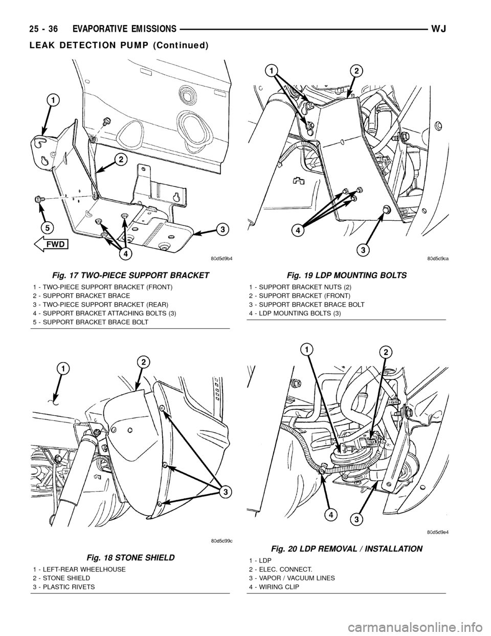
(1) Remove stone shield behind left/rear wheel
(Fig. 18). Drill out plastic rivets for removal.
(2) Remove 3 LDP mounting bolts (Fig. 19).
(3) Remove support bracket brace bolt (Fig. 17).
(4) Loosen, but do not remove 2 support bracket
nuts at frame rail (Fig. 19).
(5) To separate and lower front section of two-piece
support bracket, remove 3 attaching bolts on bottom
of support bracket (Fig. 17). While lowering support
bracket, disconnect LDP wiring clip (Fig. 20).
(6) Disconnect electrical connector at LDP (Fig.
20).
(7) Carefully remove vapor/vacuum lines at LDP
(Fig. 20).
(8) Remove LDP.
INSTALLATION
The LDP is located in the left quarter panel behind
the left/rear wheel. It is attached to a two-piece sup-
port bracket (Fig. 17). The LDP and LDP filter are
replaced (serviced) as one unit.
(1) Position LDP and carefully install vapor/vac-
uum lines to LDP and LDP filter.The vapor/vac-
uum lines and hoses must be firmly connected.
Fig. 16 LOCATION, LDP / EVAP CANISTER
1 - LEAK DETECTION PUMP
2 - EVAP CANISTER
WJEVAPORATIVE EMISSIONS 25 - 35
LEAK DETECTION PUMP (Continued)
Page 2191 of 2199

Fig. 17 TWO-PIECE SUPPORT BRACKET
1 - TWO-PIECE SUPPORT BRACKET (FRONT)
2 - SUPPORT BRACKET BRACE
3 - TWO-PIECE SUPPORT BRACKET (REAR)
4 - SUPPORT BRACKET ATTACHING BOLTS (3)
5 - SUPPORT BRACKET BRACE BOLT
Fig. 18 STONE SHIELD
1 - LEFT-REAR WHEELHOUSE
2 - STONE SHIELD
3 - PLASTIC RIVETS
Fig. 19 LDP MOUNTING BOLTS
1 - SUPPORT BRACKET NUTS (2)
2 - SUPPORT BRACKET (FRONT)
3 - SUPPORT BRACKET BRACE BOLT
4 - LDP MOUNTING BOLTS (3)
Fig. 20 LDP REMOVAL / INSTALLATION
1 - LDP
2 - ELEC. CONNECT.
3 - VAPOR / VACUUM LINES
4 - WIRING CLIP
25 - 36 EVAPORATIVE EMISSIONSWJ
LEAK DETECTION PUMP (Continued)
Page 2192 of 2199

Check the vapor/vacuum lines at the LDP, LDP
filter and EVAP canister purge solenoid for
damage or leaks. If a leak is present, a Diagnos-
tic Trouble Code (DTC) may be set.
(2) Connect electrical connector to LDP.
(3) While raising front section of support bracket,
connect LDP wiring clip (Fig. 20).
(4) Install 3 LDP mounting bolts (Fig. 19). Refer to
Torque Specifications.
(5) Join front and rear sections of two-piece sup-
port bracket by installing 3 bolts on bottom of sup-
port bracket (Fig. 17). Do not tighten bolts at this
time.
(6) Install support bracket brace bolt (Fig. 17). Do
not tighten bolt at this time.
(7) Tighten 2 support bracket nuts at frame rail
(Fig. 19). Refer to Torque Specifications.
(8) Tighten 3 support bracket bolts and brace bolt.
Refer to Torque Specifications.
(9) Position stone shield behind left/rear wheel
(Fig. 18). Install new plastic rivets.
ORVR
DESCRIPTION
The ORVR (On-Board Refueling Vapor Recovery)
system consists of a unique fuel tank, flow manage-
ment valve, fluid control valve, one-way check valve
and vapor canister. Certain ORVR components can be
found in (Fig. 1).
OPERATION
The ORVR (On-Board Refueling Vapor Recovery)
system is used to remove excess fuel tank vapors.
This is done while the vehicle is being refueled. Cer-
tain ORVR components can be found in (Fig. 1).
Fuel flowing into the fuel filler tube (approx. 1º
I.D.) creates an aspiration effect drawing air into the
fuel fill tube. During refueling, the fuel tank is
vented to the EVAP canister to capture escaping
vapors. With air flowing into the filler tube, there are
no fuel vapors escaping to the atmosphere. Once the
refueling vapors are captured by the EVAP canister,
the vehicle's computer controlled purge system draws
vapor out of the canister for the engine to burn. The
vapor flow is metered by the purge solenoid so that
there is no, or minimal impact on driveability or
tailpipe emissions.As fuel starts to flow through the fuel fill tube, it
opens the normally closed check valve and enters the
fuel tank. Vapor or air is expelled from the tank
through the control valve and on to the vapor canis-
ter. Vapor is absorbed in the EVAP canister until
vapor flow in the lines stops. This stoppage occurs
following fuel shut-off, or by having the fuel level in
the tank rise high enough to close the control valve.
This control valve contains a float that rises to seal
the large diameter vent path to the EVAP canister.
At this point in the refueling process, fuel tank pres-
sure increases, the check valve closes (preventing liq-
uid fuel from spiting back at the operator), and fuel
then rises up the fuel filler tube to shut off the dis-
pensing nozzle.
PCV VALVE
DIAGNOSIS AND TESTING - PCV VALVE/PCV
SYSTEM - 4.7L
(1) Disconnect PCV line/hose (Fig. 21) by discon-
necting rubber connecting hose at PCV valve fitting.
(2) Remove PCV valve at oil filler tube by rotating
PCV valve downward until locating tabs have been
freed at cam lock (Fig. 21). After tabs have cleared,
pull valve straight out from filler tube.To prevent
damage to PCV valve locating tabs, valve must
be pointed downward for removal. Do not force
valve from oil filler tube.
(3) After valve is removed, check condition of valve
o-ring (Fig. 21). Also, PCV valve should rattle when
shaken.
(4) Reconnect PCV valve to its connecting line/
hose.
(5) Start engine and bring to idle speed.
(6) If valve is not plugged, a hissing noise will be
heard as air passes through valve. Also, a strong vac-
uum should be felt with a finger placed at valve
inlet.
(7) If vacuum is not felt at valve inlet, check line/
hose for kinks or for obstruction. If necessary, clean
out intake manifold fitting at rear of manifold. Do
this by turning a 1/4 inch drill (by hand) through the
fitting to dislodge any solid particles. Blow out the
fitting with shop air. If necessary, use a smaller drill
to avoid removing any metal from the fitting.
WJEVAPORATIVE EMISSIONS 25 - 37
LEAK DETECTION PUMP (Continued)
Page 2194 of 2199

REMOVAL - PCV VALVE - 4.7L
The PCV valve is located on the oil filler tube (Fig.
23). Two locating tabs are located on the side of the
valve (Fig. 23). These 2 tabs fit into a cam lock in the
oil filler tube. An o-ring seals the valve to the filler
tube.
(1) Disconnect PCV line/hose (Fig. 23) by discon-
necting rubber hose at PCV valve fitting.
(2) Remove PCV valve at oil filler tube by rotating
PCV valve downward (counter-clockwise) until locat-
ing tabs have been freed at cam lock (Fig. 23). After
tabs have cleared, pull valve straight out from filler
tube.To prevent damage to PCV valve locating
tabs, valve must be pointed downward for
removal. Do not force valve from oil filler tube.
(3) After valve is removed, check condition of valve
o-ring (Fig. 23).
INSTALLATION - PCV VALVE - 4.7L
The PCV valve is located on the oil filler tube (Fig.
23). Two locating tabs are located on the side of the
valve (Fig. 23). These 2 tabs fit into a cam lock in the
oil filler tube. An o-ring seals the valve to the filler
tube.
(1) Return PCV valve back to oil filler tube by
placing valve locating tabs (Fig. 23) into cam lock.
Press PCV valve in and rotate valve upward. A slight
click will be felt when tabs have engaged cam lock.
Valve should be pointed towards rear of vehicle.
(2) Connect PCV line/hose and rubber hose to PCV
valve.
VACUUM LINES
DESCRIPTION
A vacuum schematic for emission related items can
be found on the VECI label. Refer to Vehicle Emis-
sion Control Information (VECI) Label for label loca-
tion.
VAPOR CANISTER
DESCRIPTION
A maintenance free, EVAP canister is used on all
gasoline powered models. The canister is attached to
a two-piece support bracket located behind the left-
rear wheel.
OPERATION
The EVAP canister is filled with granules of an
activated carbon mixture. Fuel vapors entering the
EVAP canister are absorbed by the charcoal granules.
The canister serves two functions: as a temporary
fuel vapor storage point while refueling the vehicle
for the ORVR system, as a temporary vapor storage
point while the engine is running.
Fuel tank pressure vents into the EVAP canister.
Fuel vapors are temporarily held in the canister until
they can be drawn into the intake manifold. The duty
cycle EVAP canister purge solenoid allows the EVAP
canister to be purged at predetermined times and at
certain engine operating conditions.
Refer to ORVR for additional information.
Fig. 23 PCV Valve/Oil Filler Tube Location
1 - O-RING
2 - LOCATING TABS
3 - CAM LOCK
4 - OIL FILLER TUBE
5 - PCV LINE/HOSE
6 - P C V VA LV E
WJEVAPORATIVE EMISSIONS 25 - 39
PCV VALVE (Continued)
Page 2195 of 2199

REMOVAL
The EVAP canister is located behind the left-rear
wheel (Fig. 24). It is attached to a two-piece support
bracket (Fig. 25).
(1) Remove rear bumper facia. Refer to Rear Facia
Removal / Installation in Frame & Bumpers section.
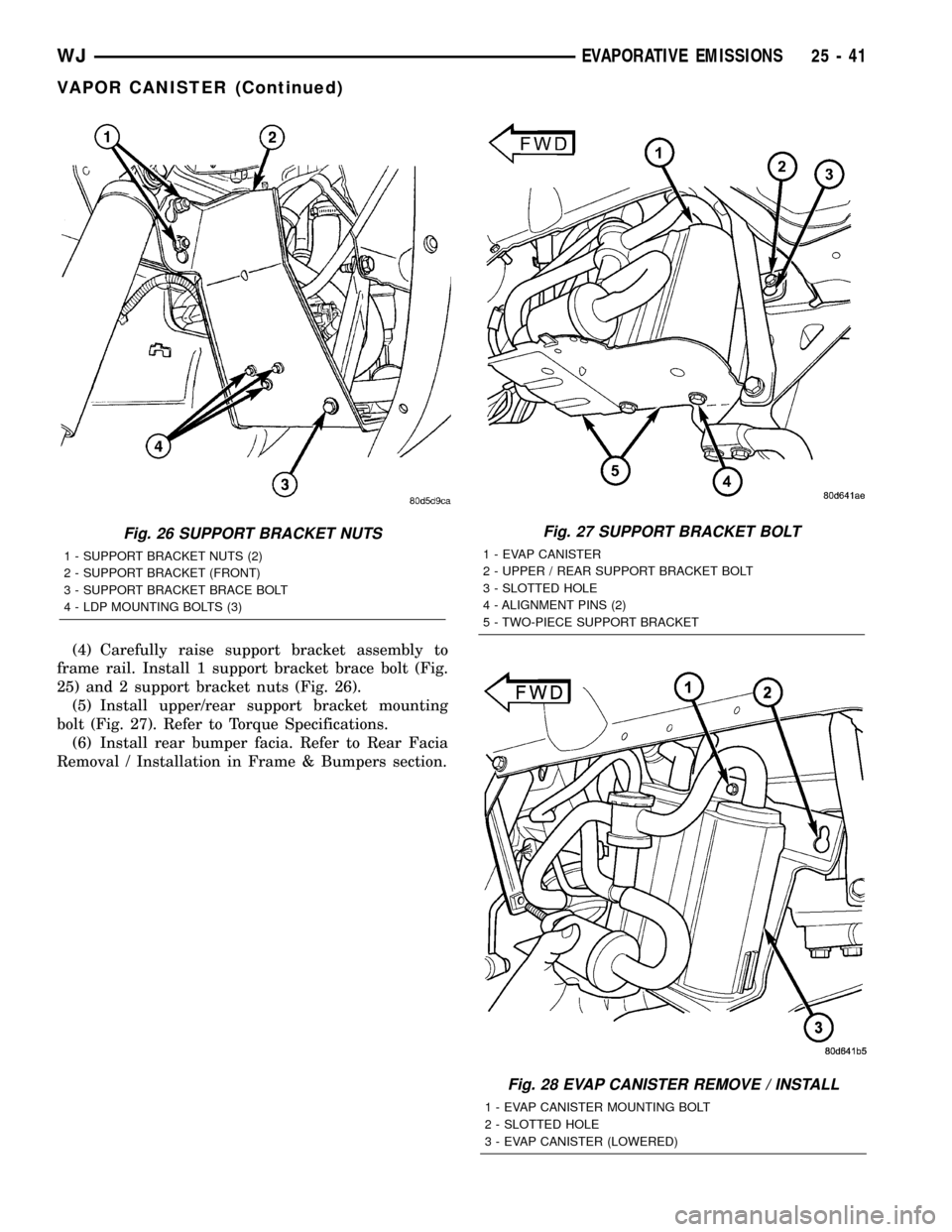
(2) Remove 1 support bracket brace bolt (Fig. 25).
(3) Loosen, but do not remove 2 support bracket
nuts (Fig. 26).
(4) Remove upper/rear support bracket mounting
bolt (Fig. 27).
(5) Carefully lower support bracket assembly to
gain access to vapor / vacuum lines. To prevent dam-
age to lines, suspend bracket assembly with rope or
string.
(6) Disconnect necessary vacuum / vapor lines at
EVAP canister.
(7) Remove EVAP canister mounting bolt (Fig. 28).
(8) Lift canister from support bracket (2 pins are
used to align canister into support bracket)
INSTALLATION
The EVAP canister is located behind the left-rear
wheel (Fig. 24). It is attached to a two-piece support
bracket (Fig. 25).
(1) Position canister to support bracket. Guide 2
alignment pins into support bracket.
(2) Install EVAP canister mounting bolt (Fig. 28).
Refer to Torque Specifications.
(3) Carefully install vapor / vacuum lines to canis-
ter.The vapor/vacuum lines and hoses must be
firmly connected. Check the vapor/vacuum
lines at the LDP, LDP filter and EVAP canister
purge solenoid for damage or leaks. If a leak is
present, a Diagnostic Trouble Code (DTC) may
be set.
Fig. 24 LOCATION, LDP / EVAP CANISTER
1 - LEAK DETECTION PUMP
2 - EVAP CANISTER
Fig. 25 TWO-PIECE SUPPORT BRACKET
1 - TWO-PIECE SUPPORT BRACKET (FRONT)
2 - SUPPORT BRACKET BRACE
3 - TWO-PIECE SUPPORT BRACKET (REAR)
4 - SUPPORT BRACKET ATTACHING BOLTS (3)
5 - SUPPORT BRACKET BRACE BOLT
25 - 40 EVAPORATIVE EMISSIONSWJ
VAPOR CANISTER (Continued)
Page 2196 of 2199

(4) Carefully raise support bracket assembly to
frame rail. Install 1 support bracket brace bolt (Fig.
25) and 2 support bracket nuts (Fig. 26).
(5) Install upper/rear support bracket mounting
bolt (Fig. 27). Refer to Torque Specifications.
(6) Install rear bumper facia. Refer to Rear Facia
Removal / Installation in Frame & Bumpers section.
Fig. 27 SUPPORT BRACKET BOLT
1 - EVAP CANISTER
2 - UPPER / REAR SUPPORT BRACKET BOLT
3 - SLOTTED HOLE
4 - ALIGNMENT PINS (2)
5 - TWO-PIECE SUPPORT BRACKET
Fig. 28 EVAP CANISTER REMOVE / INSTALL
1 - EVAP CANISTER MOUNTING BOLT
2 - SLOTTED HOLE
3 - EVAP CANISTER (LOWERED)
Fig. 26 SUPPORT BRACKET NUTS
1 - SUPPORT BRACKET NUTS (2)
2 - SUPPORT BRACKET (FRONT)
3 - SUPPORT BRACKET BRACE BOLT
4 - LDP MOUNTING BOLTS (3)
WJEVAPORATIVE EMISSIONS 25 - 41
VAPOR CANISTER (Continued)