2003 JEEP GRAND CHEROKEE frame
[x] Cancel search: framePage 1903 of 2199

(3) Install fascia, refer to (Refer to 13 - FRAMES
& BUMPERS/BUMPERS/FRONT FASCIA - INSTAL-
LATION).
HEADLAMP MOUNTING
MODULE
REMOVAL
CAUTION: Take special care when handling the
HMM not to damage the upper mounting tabs. Step
#3 must be performed prior to removing HMM from
the vehicle to prevent damage to HMM.
(1) Remove fascia, refer to (Refer to 13 - FRAMES
& BUMPERS/BUMPERS/FRONT FASCIA - REMOV-
AL).
(2) Remove inner fender liner.
(3) Reach into the wheelhouse opening and disen-
gage the retainer attaching the HMM to each side of
the body.
(4) Remove bolts attaching headlamp mounting
module to body (Fig. 10).
(5) Disconnect headlamp wire harness connectors.
(6) Separate headlamp mounting module from
vehicle.
INSTALLATION
(1) Position headlamp mounting module at vehicle.
(2) Connect headlamp wire harness connectors.
(3) Engage the retainer attaching the HMM to
each side of the body.
(4) Install bolts attaching headlamp mounting
module to body (Fig. 10).
(5) Install inner fender liner.
(6) Install front fascia, refer to (Refer to 13 -
FRAMES & BUMPERS/BUMPERS/FRONT FASCIA
- INSTALLATION).
LUGGAGE RACK
REMOVAL
NOTE: The skid strips are attached to the roof
panel with adhesive.
(1) Using a trim stick, or other suitable device, pry
support cover off.
(2) If necessary, slide the crossbars to expose the
screws attaching the slide rails to the supports.
(3) Remove the screws retaining the slide rails to
the supports.
Fig. 10 Headlamp Mounting Module
1 - CONNECTOR
2 - CONNECTOR3 - MOUNTING BRACKET
4 - HEADLAMP MODULE
23 - 30 EXTERIORWJ
GRILLE (Continued)
Page 1954 of 2199

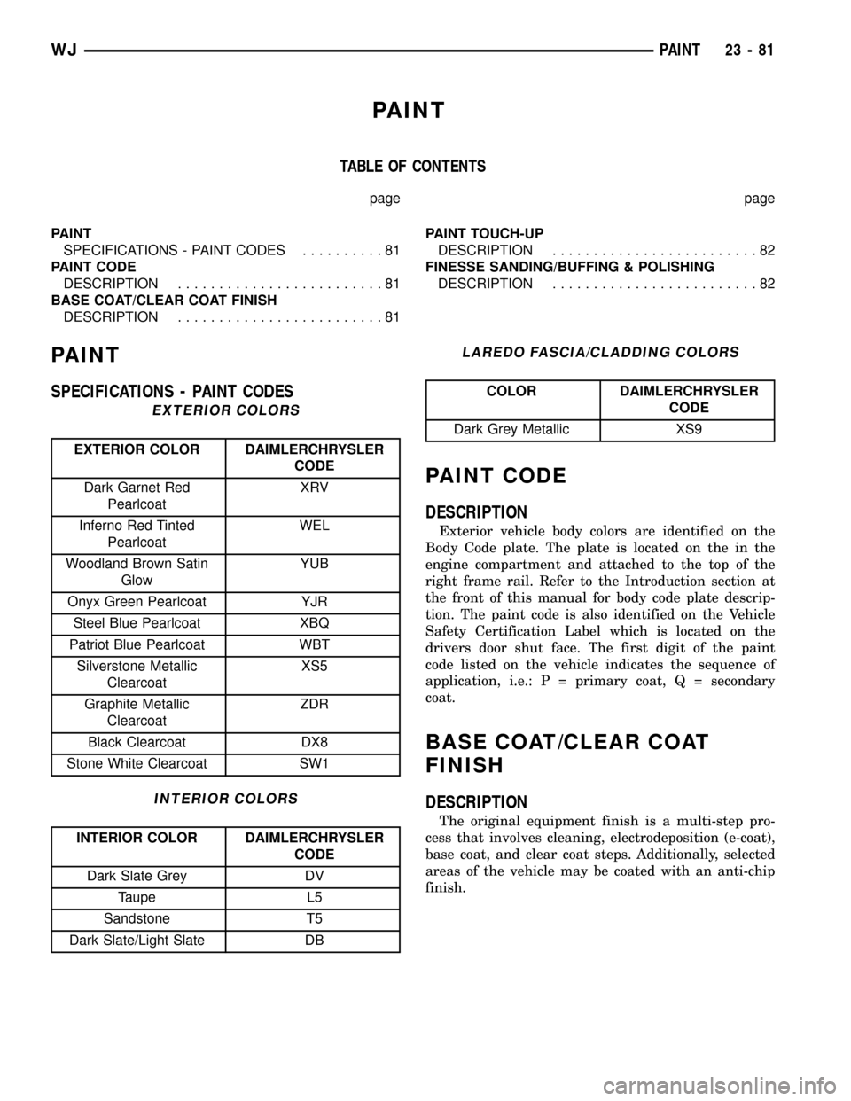
PAINT
TABLE OF CONTENTS
page page
PAINT
SPECIFICATIONS - PAINT CODES..........81
PAINT CODE
DESCRIPTION.........................81
BASE COAT/CLEAR COAT FINISH
DESCRIPTION.........................81PAINT TOUCH-UP
DESCRIPTION.........................82
FINESSE SANDING/BUFFING & POLISHING
DESCRIPTION.........................82
PAINT
SPECIFICATIONS - PAINT CODES
EXTERIOR COLORS
EXTERIOR COLOR DAIMLERCHRYSLER
CODE
Dark Garnet Red
PearlcoatXRV
Inferno Red Tinted
PearlcoatWEL
Woodland Brown Satin
GlowYUB
Onyx Green Pearlcoat YJR
Steel Blue Pearlcoat XBQ
Patriot Blue Pearlcoat WBT
Silverstone Metallic
ClearcoatXS5
Graphite Metallic
ClearcoatZDR
Black Clearcoat DX8
Stone White Clearcoat SW1
INTERIOR COLORS
INTERIOR COLOR DAIMLERCHRYSLER
CODE
Dark Slate Grey DV
Taupe L5
Sandstone T5
Dark Slate/Light Slate DB
LAREDO FASCIA/CLADDING COLORS
COLOR DAIMLERCHRYSLER
CODE
Dark Grey Metallic XS9
PAINT CODE
DESCRIPTION
Exterior vehicle body colors are identified on the
Body Code plate. The plate is located on the in the
engine compartment and attached to the top of the
right frame rail. Refer to the Introduction section at
the front of this manual for body code plate descrip-
tion. The paint code is also identified on the Vehicle
Safety Certification Label which is located on the
drivers door shut face. The first digit of the paint
code listed on the vehicle indicates the sequence of
application, i.e.: P = primary coat, Q = secondary
coat.
BASE COAT/CLEAR COAT
FINISH
DESCRIPTION
The original equipment finish is a multi-step pro-
cess that involves cleaning, electrodeposition (e-coat),
base coat, and clear coat steps. Additionally, selected
areas of the vehicle may be coated with an anti-chip
finish.
WJPAINT 23 - 81
Page 1957 of 2199

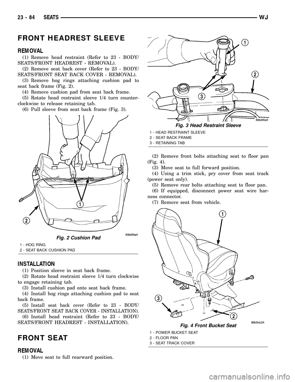
FRONT HEADREST SLEEVE
REMOVAL
(1) Remove head restraint (Refer to 23 - BODY/
SEATS/FRONT HEADREST - REMOVAL).
(2) Remove seat back cover (Refer to 23 - BODY/
SEATS/FRONT SEAT BACK COVER - REMOVAL).
(3) Remove hog rings attaching cushion pad to
seat back frame (Fig. 2).
(4) Remove cushion pad from seat back frame.
(5) Rotate head restraint sleeve 1/4 turn counter-
clockwise to release retaining tab.
(6) Pull sleeve from seat back frame (Fig. 3).
INSTALLATION
(1) Position sleeve in seat back frame.
(2) Rotate head restraint sleeve 1/4 turn clockwise
to engage retaining tab.
(3) Install cushion pad onto seat back frame.
(4) Install hog rings attaching cushion pad to seat
back frame.
(5)
Install seat back cover (Refer to 23 - BODY/
SEATS/FRONT SEAT BACK COVER - INSTALLATION).
(6) Install head restraint (Refer to 23 - BODY/
SEATS/FRONT HEADREST - INSTALLATION).
FRONT SEAT
REMOVAL
(1) Move seat to full rearward position.(2) Remove front bolts attaching seat to floor pan
(Fig. 4).
(3) Move seat to full forward position.
(4) Using a trim stick, pry cover from seat track
(power seat only).
(5) Remove rear bolts attaching seat to floor pan.
(6) If equipped, disconnect power seat wire har-
ness connector.
(7) Remove seat from vehicle.
Fig. 2 Cushion Pad
1 - HOG RING
2 - SEAT BACK CUSHION PAD
Fig. 3 Head Restraint Sleeve
1 - HEAD RESTRAINT SLEEVE
2 - SEAT BACK FRAME
3 - RETAINING TAB
Fig. 4 Front Bucket Seat
1 - POWER BUCKET SEAT
2 - FLOOR PAN
3 - SEAT TRACK COVER
23 - 84 SEATSWJ
Page 1958 of 2199

INSTALLATION
(1) Position seat on floor pan.
(2) If equipped, connect power seat wire harness
connector.
(3) Install rear bolts attaching seat to floor pan.
Tighten bolts to 40 N´m (30 ft. lbs.) torque.
(4) If equipped, install cover on seat track.
(5) Move seat to full rearward position.
(6) Install front bolts attaching seat to floor pan.
Tighten bolts to 40 N´m (30 ft. lbs.) torque.
FRONT SEAT BACK
REMOVAL
(1) Move seat to full rearward position.
(2) Remove inboard bolt attaching seat back frame
to seat cushion frame.
(3) Move seat to full forward position.
(4) Move seat back to full recline position.
(5) Remove screws attaching seat side shield to
seat frame.
(6) Disconnect wire harness connector from
recliner motor, if equipped.
(7) From the underside of the seat, disconnect the
wire harness connector for the power lumber and/or
heated seat, if equipped.
(8) Remove outboard bolts attaching recliner to
seat cushion frame.
(9) Route the power lumber and/or heated seat
harness through the seat cushion cover, if equipped.
(10) Separate seat back from seat cushion.
INSTALLATION
(1) Position seat back on seat cushion.
(2) Route the power lumber and heater harness
through the seat cushion cover, if equipped.
(3) Install recliner bolts attaching seat back frame
to seat cushion frame. Tighten bolts to 28 N´m (20 ft.
lbs.) torque.
(4) Install the inboard bolt attaching seat back
frame to seat cushion frame. Tighten bolt to 47N´m
(35 ft.lbs.).
(5) Connect wire harness connector to recliner
motor and/or heated seat, if equipped.
(6) From the underside of the seat, connect the
power lumber and/or heated seat wire harness con-
nector to the seat harness, if equipped.
(7) Install screws attaching seat side shield to seat
frame.
FRONT SEAT BACK COVER
REMOVAL
(1) Remove head restraint (Refer to 23 - BODY/
SEATS/FRONT HEADREST - REMOVAL).
(2) Using a trim stick, carefully pry head restraint
release button caps from the top of seat back.
(3) Remove seat back (Refer to 23 - BODY/SEATS/
FRONT SEAT BACK - REMOVAL).
(4) Disengage J-strap at base of seat back.
(5) Slide hand between the face of the seat back
pad and the cushion cover and carefully separate
hook and loop fastener (Fig. 5).
(6) Roll cover upward and disengage hog rings.
(7) Roll cover upward to top of seat back.
(8) Separate cover from seat back.
INSTALLATION
(1) Position cover inside-out at the top of seat
back.
(2) Roll cover downward.
(3) Engage hog rings.
(4) Align seat back cover with hook and loop fas-
teners and secure.
(5) Roll cover downward.
(6) Engage J-strap at base of seat back.
(7) Install seat back (Refer to 23 - BODY/SEATS/
FRONT SEAT BACK - INSTALLATION).
NOTE: The taller head restraint release button cap
is positioned on the left hand side and the head
restraint button cap with the hidden button is posi-
tioned on the right hand side.
Fig. 5 Seat Back Cover
1 - SEAT BACK COVER
2 - HOOK AND LOOP FASTENER
3 - SEAT BACK PAD
WJSEATS 23 - 85
FRONT SEAT (Continued)
Page 1959 of 2199

(8) Position head restraint release button caps on
head restraint sleeves and press to secure.
(9) Install head restraint (Refer to 23 - BODY/
SEATS/FRONT HEADREST - INSTALLATION).
FRONT SEAT CUSHION/COVER
REMOVAL
(1) Remove seat from vehicle (Refer to 23 - BODY/
SEATS/FRONT SEAT - REMOVAL).
(2) Remove seat back (Refer to 23 - BODY/SEATS/
FRONT SEAT BACK - REMOVAL).
(3) Disengage J-straps attaching cushion cover to
seat cushion frame.
(4) Disengage hog rings attaching cushion cover to
cushion frame at rear of seat along bottom of cushion
cover (Fig. 6).
(5) Roll up edges of cover and route seat function
switches through access hole on outboard side of seat
cushion, if equipped.
(6) Disengage seat cushion heater element connec-
tor, if equipped.
(7) Disengage hog rings attaching cover to cushion
along cover insert.
(8) Separate seat cushion cover from seat cushion.
INSTALLATION
(1) Position seat cover on cushion.
(2) Engage hog rings attaching cushion cover to
cushion along insert.
(3) Engage seat cushion heater element connector,
if equipped.
(4) Route seat function switches through access
hole on outboard side of seat cushion, if equipped.(5) Engage J-straps attaching cushion cover to seat
cushion frame.
(6) Engage hog rings attaching cushion cover to
cushion frame.
(7) Install seat back (Refer to 23 - BODY/SEATS/
FRONT SEAT BACK - INSTALLATION).
(8) Install seat (Refer to 23 - BODY/SEATS/
FRONT SEAT - INSTALLATION).
FRONT SEAT SIDE SHIELD
REMOVAL
(1) Remove screws attaching side shield to seat
frame.
(2) Disconnect wire harness connectors from power
seat and power lumbar switches, if equipped.
(3) Separate side shield from seat.
INSTALLATION
(1) Position side shield on seat.
(2) Connect wire harness connectors to power seat
and power lumbar switches, if equipped.
(3) Install screws attaching side shield to seat
frame.
SEAT TRACK & RECLINER
ASSEMBLY
REMOVAL
(1) Remove seat back (Refer to 23 - BODY/SEATS/
FRONT SEAT BACK - REMOVAL).
(2) Disengage J-strap at base of seat back.
(3) Roll seat back cover upward to access bolts
attaching recliner to seat back frame.
(4) Remove bolts attaching recliner to seat back
frame.
(5) Separate recliner from seat back.
INSTALLATION
(1) Position recliner on seat back.
(2) Install bolts attaching recliner to seat back
frame. Tighten bolts to 28 N´m (20 ft. lbs.) torque.
(3) Roll seat back cover downward.
(4) Engage J-strap at base of seat back.
(5) Install seat back (Refer to 23 - BODY/SEATS/
FRONT SEAT BACK - INSTALLATION).Fig. 6 Seat Cushion Cover
1 - HOG RING
2 - CUSHION COVER
23 - 86 SEATSWJ
FRONT SEAT BACK COVER (Continued)
Page 1960 of 2199

SEAT TRACK ADJUSTER
REMOVAL
(1) Remove seat (Refer to 23 - BODY/SEATS/
FRONT SEAT - REMOVAL).
(2) Remove side shield (Refer to 23 - BODY/
SEATS/FRONT SEAT SIDE SHIELD - REMOVAL).
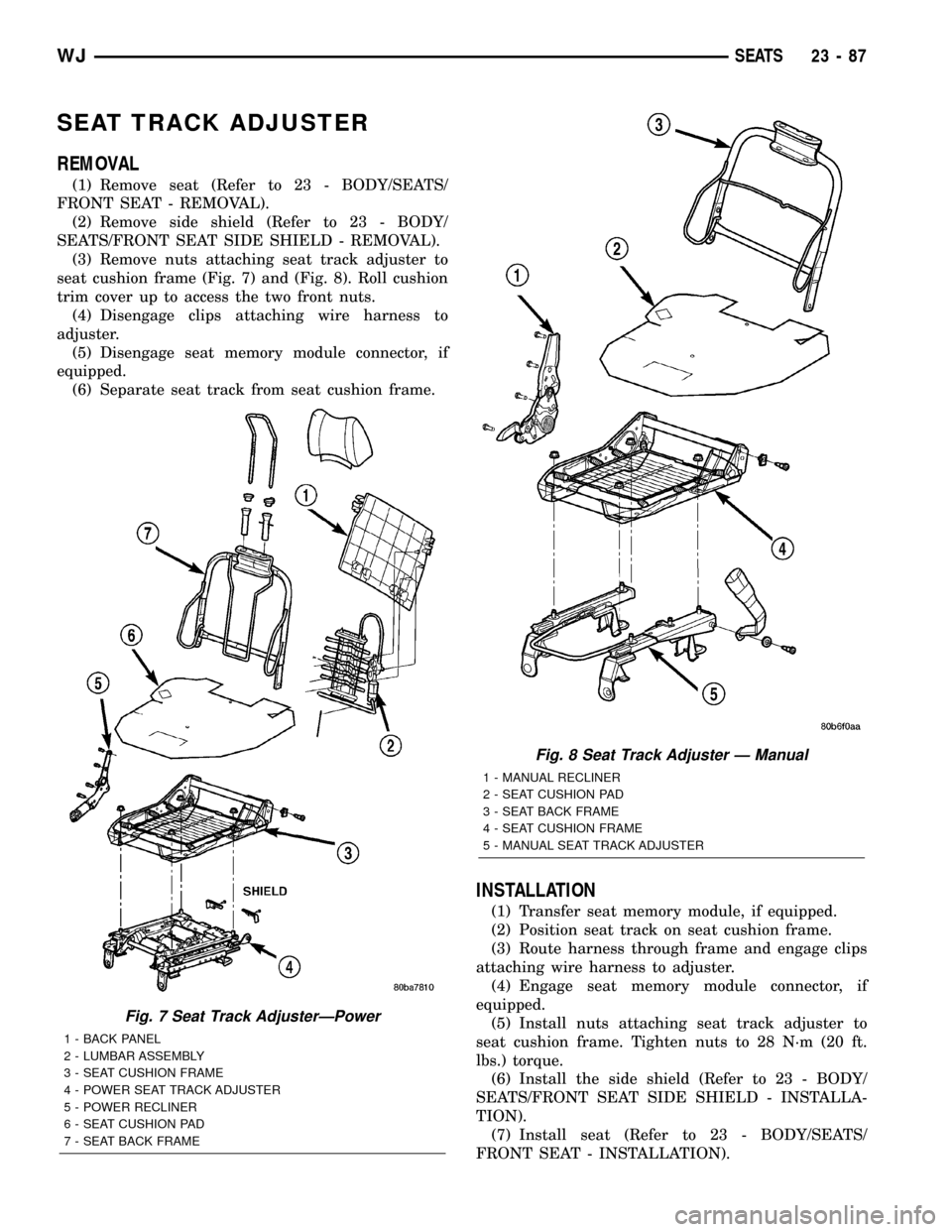
(3) Remove nuts attaching seat track adjuster to
seat cushion frame (Fig. 7) and (Fig. 8). Roll cushion
trim cover up to access the two front nuts.
(4) Disengage clips attaching wire harness to
adjuster.
(5) Disengage seat memory module connector, if
equipped.
(6) Separate seat track from seat cushion frame.
INSTALLATION
(1) Transfer seat memory module, if equipped.
(2) Position seat track on seat cushion frame.
(3) Route harness through frame and engage clips
attaching wire harness to adjuster.
(4) Engage seat memory module connector, if
equipped.
(5) Install nuts attaching seat track adjuster to
seat cushion frame. Tighten nuts to 28 N´m (20 ft.
lbs.) torque.
(6) Install the side shield (Refer to 23 - BODY/
SEATS/FRONT SEAT SIDE SHIELD - INSTALLA-
TION).
(7) Install seat (Refer to 23 - BODY/SEATS/
FRONT SEAT - INSTALLATION).
Fig. 7 Seat Track AdjusterÐPower
1 - BACK PANEL
2 - LUMBAR ASSEMBLY
3 - SEAT CUSHION FRAME
4 - POWER SEAT TRACK ADJUSTER
5 - POWER RECLINER
6 - SEAT CUSHION PAD
7 - SEAT BACK FRAME
Fig. 8 Seat Track Adjuster Ð Manual
1 - MANUAL RECLINER
2 - SEAT CUSHION PAD
3 - SEAT BACK FRAME
4 - SEAT CUSHION FRAME
5 - MANUAL SEAT TRACK ADJUSTER
WJSEATS 23 - 87
Page 1962 of 2199

REAR HEADREST SLEEVE
REMOVAL
(1) Remove seat back (Refer to 23 - BODY/SEATS/
REAR SEAT BACK - REMOVAL).
(2) Remove head rest (Refer to 23 - BODY/SEATS/
REAR HEADREST - REMOVAL).
(3) Remove head rest caps.
(4) Remove seat back cover (Refer to 23 - BODY/
SEATS/REAR SEAT BACK COVER - REMOVAL).
(5) Rotate head rest sleeve 1/4 turn counter-clock-
wise to release retaining tab.
(6) Pull sleeve from seat back frame.
INSTALLATION
(1) Position sleeve in seat back frame.
(2) Rotate head rest sleeve 1/4 turn clockwise to
engage retaining tab.
(3) Install seat back cover (Refer to 23 - BODY/
SEATS/REAR SEAT BACK COVER - INSTALLA-
TION).
(4) Install head rest caps.
NOTE: The head rest cap with the taller button is
always on the inboard side of the seat back.
(5) Install the head rest (Refer to 23 - BODY/
SEATS/REAR HEADREST - INSTALLATION).
NOTE: The folding head rest release knob is always
on the outboard side.
(6) Install the seat back (Refer to 23 - BODY/
SEATS/REAR SEAT BACK - INSTALLATION).
REAR SEAT BACK
REMOVAL
(1) Move rear seat cushions to forward cargo posi-
tion.
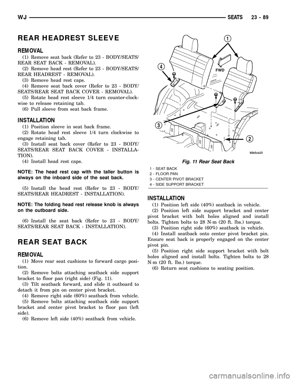
(2) Remove bolts attaching seatback side support
bracket to floor pan (right side) (Fig. 11).
(3) Tilt seatback forward, and slide it outboard to
detach it from pin on center pivot bracket.
(4) Remove right side (60%) seatback from vehicle.
(5) Remove bolts attaching seatback side support
bracket and center pivot bracket to floor pan (left
side).
(6) Remove left side (40%) seatback from vehicle.
INSTALLATION
(1) Position left side (40%) seatback in vehicle.
(2) Position left side support bracket and center
pivot bracket with bolt holes aligned and install
bolts. Tighten bolts to 28 N´m (20 ft. lbs.) torque.
(3) Position right side (60%) seatback in vehicle.
(4) Install seatback onto center pivot bracket pin.
Ensure seat back is properly engaged on the center
pivot pin.
(5) Position right side support bracket with bolt
holes aligned and install bolts. Tighten bolts to 28
N´m (20 ft. lbs.) torque.
(6) Return seat cushions to seating position.
Fig. 11 Rear Seat Back
1 - SEAT BACK
2 - FLOOR PAN
3 - CENTER PIVOT BRACKET
4 - SIDE SUPPORT BRACKET
WJSEATS 23 - 89
Page 1963 of 2199

REAR SEAT BACK COVER
REMOVAL
(1) Remove seat back (Refer to 23 - BODY/SEATS/
REAR SEAT BACK - REMOVAL).
(2) Remove head restraint (Refer to 23 - BODY/
SEATS/REAR HEADREST - REMOVAL).
(3) Remove head restraint caps.
(4) Disengage J-straps on outboard side of seat
back.
(5) Disengage J-straps at base of seat back.
(6) Remove screws attaching latch release handle
to seat back frame.
(7) Roll seat back cover upward.
(8) Disengage hook and loop fasteners attaching
seat back cover to seat back pad (Fig. 12).
(9) Roll seat back cover upward and route latch
release handle through seat back cover.
(10) Separate seat back cover from seat back.
(11) Separate seat back pad from seat back frame.
INSTALLATION
(1) Position seat back cover and pad on seat back
frame.
(2) Route latch release handle through seat back
cover.(3) Roll seat back cover partially downward align-
ing holes in seat back cover for head restraint and
latch release handle.
(4) Roll seat back cover downward align and
engage hook and loop fasteners to seat back pad.
(5) Engage J-straps at base of seat back.
(6) Engage J-straps on outboard side of seat back.
(7) Install screws attaching latch release handle to
seat back frame.
(8) Install head restraint (Refer to 23 - BODY/
SEATS/REAR HEADREST - INSTALLATION).
(9) Install seat back (Refer to 23 - BODY/SEATS/
REAR SEAT BACK - INSTALLATION).
REAR SEAT CUSHION
REMOVAL
(1) Disengage seat cushion at rear by pulling
upward on release strap.
(2) Remove bolts attaching seat cushion to floor
pan (Fig. 13).
(3) Remove seat cushion from vehicle.
INSTALLATION
(1) Position seat cushion in vehicle.
(2) Install bolts attaching seat cushion to floor
pan. Tighten bolts to 11 N´m (8 ft. lbs.) torque.
(3) Lock seat cushion down by pressing firmly on
center of cushion until latch engages.
Fig. 12 Rear Seat Back Cover
1 - SEAT BACK COVER
2 - SEAT BACK PAD
3 - HOOK AND LOOP FASTENERFig. 13 Rear Seat Cushion
1 - SEAT CUSHION
2 - FLOOR PAN
23 - 90 SEATSWJ