2003 JEEP GRAND CHEROKEE frame
[x] Cancel search: framePage 1518 of 2199

INSTALLATION - 3/8(PRESSURE HOSE
NOTE: Lubrication and a new o-ring must be used
when reinstalling.
(1) Install the hoses to the vehicle.
(2) Reconnect the high pressure hose to the
hydraulic fan motor (Fig. 10) Tighten the hose to
22.5 N´m (17 ft.lbs.).
(3) Reconnect the high pressure hose to the power
steering gear (Fig. 10) Tighten the hose to 22.5 N´m
(17 ft.lbs.).
(4) Install the hose to the clipped position on the
fan shroud.
(5) Install the metal skid plate.
(6) Install the air box,(Refer to 9 - ENGINE/AIR
INTAKE SYSTEM/AIR CLEANER HOUSING -
INSTALLATION).
(7) Refill the power steering fluid and bleed the
system,(Refer to 19 - STEERING/PUMP - STAN-
DARD PROCEDURE).
INSTALLATION - 3/8(RETURN HOSE
(1) Install the hoses to the vehicle.
(2) Reconnect the rubber hose to the steering
cooler outlet tube (Fig. 12) Tighten the hose clamp.
(3) Reconnect the rubber hose to the power steer-
ing reservoir (Fig. 12) Tighten the hose clamp.
(4) Install the air box,(Refer to 9 - ENGINE/AIR
INTAKE SYSTEM/AIR CLEANER HOUSING -
INSTALLATION).
(5) Refill the power steering fluid and bleed the
system,(Refer to 19 - STEERING/PUMP - STAN-
DARD PROCEDURE).
INSTALLATION - 3/8(GEAR OUTLET HOSE
NOTE: Lubrication and a new o-ring must be used
when reinstalling.
(1) Install the hoses to the vehicle.
(2) Reconnect the rubber hose to the steering
cooler inlet tube (Fig. 11) Tighten the hose clamp.
(3)
Reconnect the metal tube to the power steering
gear (Fig. 11) Tighten the hose to 22.5 N´m (17 ft.lbs.).
(4) Install the air box,(Refer to 9 - ENGINE/AIR
INTAKE SYSTEM/AIR CLEANER HOUSING -
INSTALLATION).
(5) Refill the power steering fluid and bleed the
system,(Refer to 19 - STEERING/PUMP - STAN-
DARD PROCEDURE).
INSTALLATION - INLET COOLER HOSE
(1) Install the cooler hose to the vehicle.
(2) Reconnect the cooler hose at the gear.
(3) Reconnect the lower hose at cooler (Fig. 6).
Tighten the hose to 22.5 N´m (17 ft.lbs.)
(4) Install the bracket holding the cooler hoses
(Fig. 13).(5) Install the air box,(Refer to 9 - ENGINE/AIR
INTAKE SYSTEM/AIR CLEANER HOUSING -
INSTALLATION).
(6) Install the grille opening reinforcement panel
(7) Install the front fascia grille assembly, (Refer to
13 - FRAMES & BUMPERS/BUMPERS/FRONT
FASCIA - INSTALLATION).
(8) Reconnect negative battery cable at battery.
(9) Refill the power steering fluid and bleed the
system,(Refer to 19 - STEERING/PUMP - STAN-
DARD PROCEDURE).
INSTALLATION - OUTLET COOLER HOSE
(1) Install the cooler hose to the vehicle.
(2) Reconnect the cooler hose at the reservoir.
(3) Reconnect the upper hose at the cooler (Fig. 6).
Tighten the hose to 22.5 N´m (17 ft. lbs.)
(4) Install the bracket holding the cooler hoses
(Fig. 13). Tighten the bracket to 22.5 N´m (17 ft. lbs.)
(5) Install the air box,(Refer to 9 - ENGINE/AIR
INTAKE SYSTEM/AIR CLEANER HOUSING -
INSTALLATION).
(6) Install the grille opening reinforcement panel
(7) Install the front fascia grille assembly, (Refer to
13 - FRAMES & BUMPERS/BUMPERS/FRONT
FASCIA - INSTALLATION).
(8) Reconnect negative battery cable at battery.
(9) Refill the power steering fluid and bleed the
system,(Refer to 19 - STEERING/PUMP - STAN-
DARD PROCEDURE).
PULLEY
DESCRIPTION
POWER STEERING PUMP PULLEY - 3.1L
DIESEL
To service the power steering pump pulley on the
3.1L turbo diesel engine. Refer to the power steering
pump removal and installation procedure in this
group. The pulley must be removed to service the
pump assembly. Detailed instructions are provided in
the pump procedure.
REMOVAL
CAUTION: On vehicles equipped with the 4.0L or
4.7L, Do not reuse the old power steering pump
pulley it is not intended for reuse. A new pulley
must be installed if removed.
(1) Remove pump assembly.
(2) Remove pulley from pump with Puller C-4333
or equivalent puller (Fig. 14).
WJPUMP 19 - 41
HOSES - 4.7L (Continued)
Page 1547 of 2199
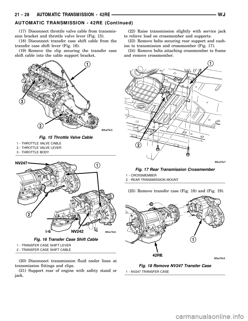
(17) Disconnect throttle valve cable from transmis-
sion bracket and throttle valve lever (Fig. 15).
(18) Disconnect transfer case shift cable from the
transfer case shift lever (Fig. 16).
(19) Remove the clip securing the transfer case
shift cable into the cable support bracket.
(20) Disconnect transmission fluid cooler lines at
transmission fittings and clips.
(21) Support rear of engine with safety stand or
jack.(22) Raise transmission slightly with service jack
to relieve load on crossmember and supports.
(23) Remove bolts securing rear support and cush-
ion to transmission and crossmember (Fig. 17).
(24) Remove bolts attaching crossmember to frame
and remove crossmember.
(25) Remove transfer case (Fig. 18) and (Fig. 19).
Fig. 15 Throttle Valve Cable
1 - THROTTLE VALVE CABLE
2 - THROTTLE VALVE LEVER
3 - THROTTLE BODY
Fig. 16 Transfer Case Shift Cable
1 - TRANSFER CASE SHIFT LEVER
2 - TRANSFER CASE SHIFT CABLE
Fig. 17 Rear Transmission Crossmember
1 - CROSSMEMBER
2 - REAR TRANSMISSION MOUNT
Fig. 18 Remove NV247 Transfer Case
1 - NV247 TRANSFER CASE
21 - 28 AUTOMATIC TRANSMISSION - 42REWJ
AUTOMATIC TRANSMISSION - 42RE (Continued)
Page 1561 of 2199

(11) Move transmission forward. Then raise, lower
or tilt transmission to align converter housing with
engine block dowels.
(12) Carefully work transmission forward and over
engine block dowels until converter hub is seated in
crankshaft.
(13) Install two bolts to attach converter housing
to engine.
(14) Install the upper transmission bending braces
to the torque converter housing and the overdrive
unit. Tighten the bolts to 41 N´m (30 ft.lbs.).
(15) Install remaining torque converter housing to
engine bolts. Tighten to 68 N´m (50 ft.lbs.).
(16) Install rear transmission crossmember.
Tighten crossmember to frame bolts to 68 N´m (50
ft.lbs.).
(17) Install rear support to transmission. Tighten
bolts to 47 N´m (35 ft.lbs.).
(18) Lower transmission onto crossmember and
install bolts attaching transmission mount to cross-
member. Tighten clevis bracket to crossmember bolts
to 47 N´m (35 ft.lbs.). Tighten the clevis bracket to
rear support bolt to 68 N´m (50 ft.lbs.).
(19) Remove engine support fixture.
(20) Install crankshaft position sensor. (Refer to 14
- FUEL SYSTEM/FUEL INJECTION/CRANKSHAFT
POSITION SENSOR - INSTALLATION)
(21) Install new plastic retainer grommet on any
shift cable that was disconnected. Grommets should
not be reused. Use pry tool to remove rod from grom-
met and cut away old grommet. Use pliers to snap
new grommet into cable and to snap grommet onto
lever.
(22) Connect gearshift and throttle valve cable to
transmission.
(23) Connect wires to park/neutral position switch
and transmission solenoid connector. Be sure trans-
mission harnesses are properly routed.CAUTION: It is essential that correct length bolts be
used to attach the converter to the driveplate. Bolts
that are too long will damage the clutch surface
inside the converter.
(24) Install all torque converter-to-driveplate bolts
by hand.
(25) Verify that the torque converter is pulled
flush to the driveplate. Tighten bolts to 31 N´m (270
in. lbs.).
(26) Install converter housing access cover. Tighten
bolt to 23 N´m (200 in.lbs.).
(27) Install the bell housing brace to the torque
converter cover and the engine to transmission bend-
ing brace. Tighten the bolts and nut to 41 N´m (30
ft.lbs.).
(28) Install starter motor (Refer to 8 - ELECTRI-
CAL/STARTING/STARTER MOTOR - INSTALLA-
TION) and cooler line bracket.
(29) Connect cooler lines to transmission.
(30) Install transmission fill tube. Install new seal
on tube before installation.
(31) Install exhaust components.
(32) Install transfer case. Tighten transfer case
nuts to 35 N´m (26 ft.lbs.).
(33) Install the transfer case shift cable to the
cable support bracket and the transfer case shift
lever.
(34) Align and connect propeller shaft(s).
(35) Adjust gearshift linkage and throttle valve
cable if necessary.
(36) Lower vehicle.
(37) Fill transmission with MopartATF +4, type
9602, fluid.
21 - 42 AUTOMATIC TRANSMISSION - 42REWJ
AUTOMATIC TRANSMISSION - 42RE (Continued)
Page 1703 of 2199
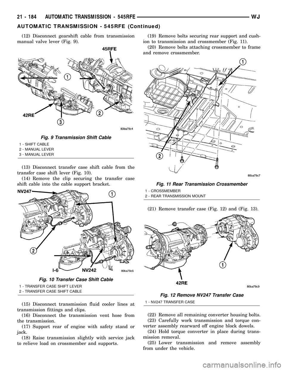
(12) Disconnect gearshift cable from transmission
manual valve lever (Fig. 9).
(13) Disconnect transfer case shift cable from the
transfer case shift lever (Fig. 10).
(14) Remove the clip securing the transfer case
shift cable into the cable support bracket.
(15) Disconnect transmission fluid cooler lines at
transmission fittings and clips.
(16) Disconnect the transmission vent hose from
the transmission.
(17) Support rear of engine with safety stand or
jack.
(18) Raise transmission slightly with service jack
to relieve load on crossmember and supports.(19) Remove bolts securing rear support and cush-
ion to transmission and crossmember (Fig. 11).
(20) Remove bolts attaching crossmember to frame
and remove crossmember.
(21) Remove transfer case (Fig. 12) and (Fig. 13).
(22) Remove all remaining converter housing bolts.
(23) Carefully work transmission and torque con-
verter assembly rearward off engine block dowels.
(24) Hold torque converter in place during trans-
mission removal.
(25) Lower transmission and remove assembly
from under the vehicle.
Fig. 9 Transmission Shift Cable
1 - SHIFT CABLE
2 - MANUAL LEVER
3 - MANUAL LEVER
Fig. 10 Transfer Case Shift Cable
1 - TRANSFER CASE SHIFT LEVER
2 - TRANSFER CASE SHIFT CABLE
Fig. 11 Rear Transmission Crossmember
1 - CROSSMEMBER
2 - REAR TRANSMISSION MOUNT
Fig. 12 Remove NV247 Transfer Case
1 - NV247 TRANSFER CASE
21 - 184 AUTOMATIC TRANSMISSION - 545RFEWJ
AUTOMATIC TRANSMISSION - 545RFE (Continued)
Page 1717 of 2199
(5) Carefully insert converter in oil pump. Then
rotate converter back and forth until fully seated in
pump gears.
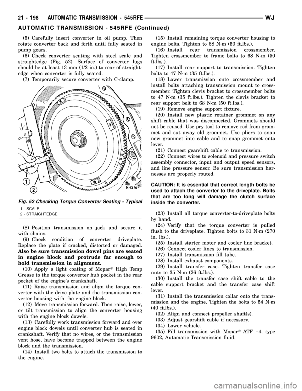
(6) Check converter seating with steel scale and
straightedge (Fig. 52). Surface of converter lugs
should be at least 13 mm (1/2 in.) to rear of straight-
edge when converter is fully seated.
(7) Temporarily secure converter with C-clamp.
(8) Position transmission on jack and secure it
with chains.
(9) Check condition of converter driveplate.
Replace the plate if cracked, distorted or damaged.
Also be sure transmission dowel pins are seated
in engine block and protrude far enough to
hold transmission in alignment.
(10) Apply a light coating of MopartHigh Temp
Grease to the torque converter hub pocket in the rear
pocket of the engine's crankshaft.
(11) Raise transmission and align the torque con-
verter with the drive plate and the transmission con-
verter housing with the engine block.
(12) Move transmission forward. Then raise, lower,
or tilt transmission to align the converter housing
with the engine block dowels.
(13) Carefully work transmission forward and over
engine block dowels until converter hub is seated in
crankshaft. Verify that no wires, or the transmission
vent hose, have become trapped between the engine
block and the transmission.
(14) Install two bolts to attach the transmission to
the engine.(15) Install remaining torque converter housing to
engine bolts. Tighten to 68 N´m (50 ft.lbs.).
(16) Install rear transmission crossmember.
Tighten crossmember to frame bolts to 68 N´m (50
ft.lbs.).
(17) Install rear support to transmission. Tighten
bolts to 47 N´m (35 ft.lbs.).
(18) Lower transmission onto crossmember and
install bolts attaching transmission mount to cross-
member. Tighten clevis bracket to crossmember bolts
to 47 N´m (35 ft.lbs.). Tighten the clevis bracket to
rear support bolt to 68 N´m (50 ft.lbs.).
(19) Remove engine support fixture.
(20) Install new plastic retainer grommet on any
shift cable that was disconnected. Grommets should
not be reused. Use pry tool to remove rod from grom-
met and cut away old grommet. Use pliers to snap
new grommet into cable and to snap grommet onto
lever.
(21) Connect gearshift cable to transmission.
(22) Connect wires to solenoid and pressure switch
assembly connector, input and output speed sensors,
and line pressure sensor. Be sure transmission har-
nesses are properly routed.
CAUTION: It is essential that correct length bolts be
used to attach the converter to the driveplate. Bolts
that are too long will damage the clutch surface
inside the converter.
(23) Install all torque converter-to-driveplate bolts
by hand.
(24) Verify that the torque converter is pulled
flush to the driveplate. Tighten bolts to 31 N´m (270
in. lbs.).
(25) Install starter motor and cooler line bracket.
(26) Connect cooler lines to transmission.
(27) Install transmission fill tube.
(28) Install exhaust components.
(29) Install transfer case. Tighten transfer case
nuts to 35 N´m (26 ft.lbs.).
(30) Install the transfer case shift cable to the
cable support bracket and the transfer case shift
lever.
(31) Install the transmission collar onto the trans-
mission and the engine. Tighten the bolts to 54 N´m
(40 ft.lbs.).
(32) Align and connect propeller shaft(s).
(33) Adjust gearshift cable if necessary.
(34) Lower vehicle.
(35) Fill transmission with MopartATF +4, type
9602, Automatic Transmission fluid.
Fig. 52 Checking Torque Converter Seating - Typical
1 - SCALE
2 - STRAIGHTEDGE
21 - 198 AUTOMATIC TRANSMISSION - 545RFEWJ
AUTOMATIC TRANSMISSION - 545RFE (Continued)
Page 1877 of 2199
SPECIFICATIONS - TORQUE
TORQUE SPECIFICATIONS
DESCRIPTION N´m Ft. Lbs. In. Lbs.
BUCKET SEAT BACK FRAME RECLINER BOLTS TO SEAT CUSHION
FRAME28 20 Ð
BUCKET SEAT RECLINER TO SEAT BACK FRAME BOLTS 28 20 Ð
BUCKET SEAT TRACK ADJUSTER NUTS TO SEAT CUSHION FRAME 28 20 Ð
FRONT BUCKET SEAT TO FLOOR PAN BOLTS 40 30 Ð
FRONT BUCKET SEAT TO FLOOR PAN FRONT BOLTS 40 30 Ð
FRONT DOOR HINGE BOLTS 35 26 Ð
FRONT DOOR LATCH TO DOOR SCREWS 10 Ð 89
FRONT DOOR STRIKER TO B-PILLAR 28 20 Ð
HOOD LATCH TO RADIATOR CROSSMEMBER 11 8 Ð
LIFT GATE LATCH STRIKER TO D-PILLAR NUTS 10 Ð 89
REAR DOOR LATCH TO DOOR SCREWS 10 Ð 89
REAR DOOR STRIKER TO C-PILLAR SCREWS 28 20 Ð
REAR SEAT BACK LATCH/HINGE TO SEAT BACK FRAME 28 20 Ð
REAR SEAT BACK LEFT SIDE SUPPORT BRACKET TO CENTER PIVOT
BRACKET28 20 Ð
REAR SEAT BACK RIGHT SIDE SUPPORT BRACKET 28 20 Ð
REAR SEAT CUSHION LATCH BASE PANEL SCREWS 8 Ð 75
REAR SEAT CUSHION TO FLOOR PAN BOLTS 11 8 Ð
SUNROOF MODULE TO ROOF PANEL NUTS 11 8 Ð
SPECIAL TOOLS
BODY
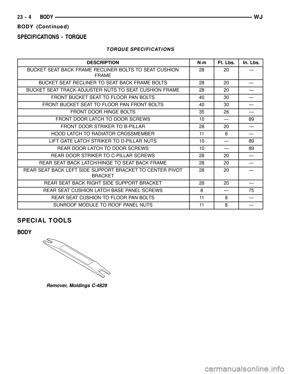
Remover, Moldings C-4829
23 - 4 BODYWJ
BODY (Continued)
Page 1887 of 2199
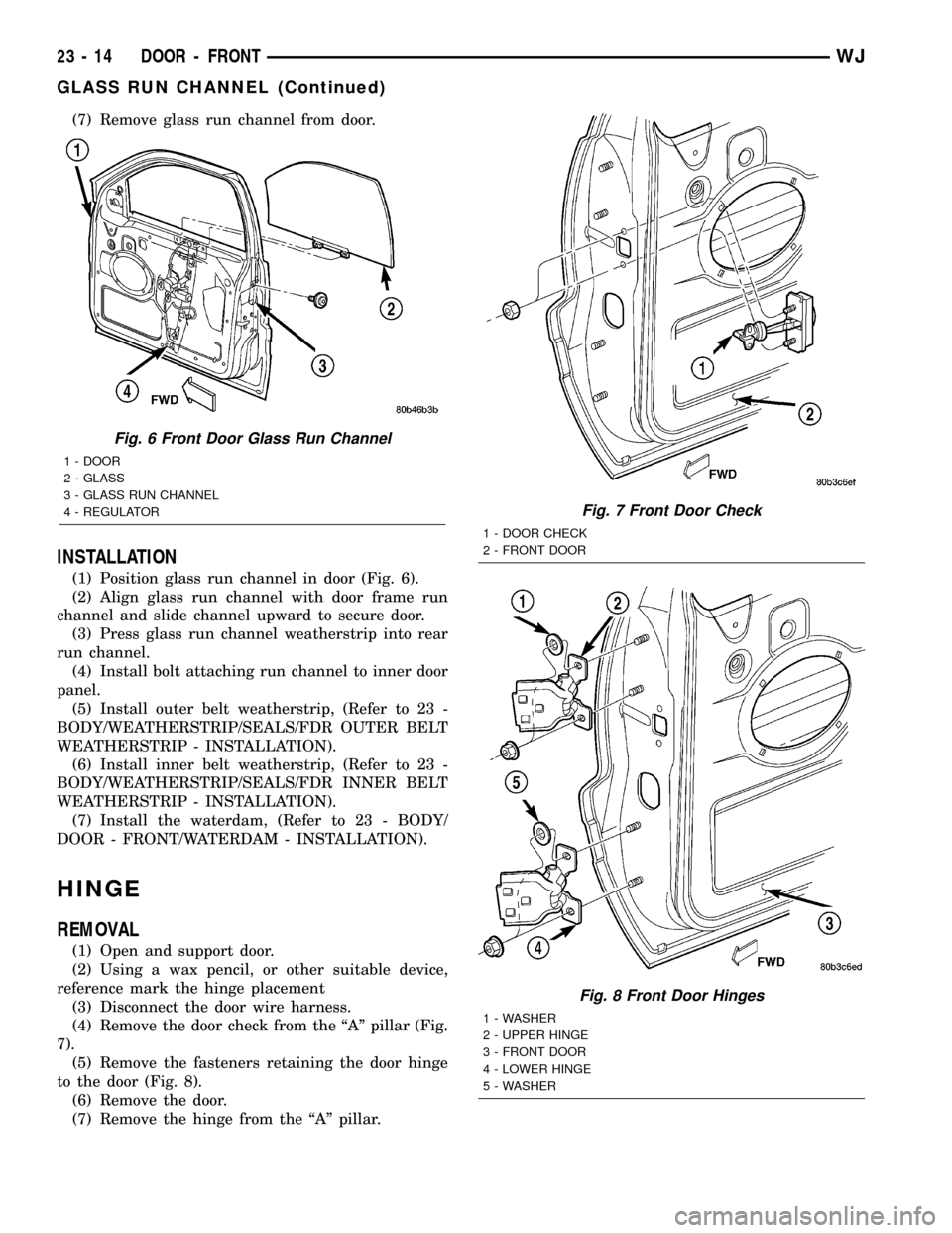
(7) Remove glass run channel from door.
INSTALLATION
(1) Position glass run channel in door (Fig. 6).
(2) Align glass run channel with door frame run
channel and slide channel upward to secure door.
(3) Press glass run channel weatherstrip into rear
run channel.
(4) Install bolt attaching run channel to inner door
panel.
(5) Install outer belt weatherstrip, (Refer to 23 -
BODY/WEATHERSTRIP/SEALS/FDR OUTER BELT
WEATHERSTRIP - INSTALLATION).
(6) Install inner belt weatherstrip, (Refer to 23 -
BODY/WEATHERSTRIP/SEALS/FDR INNER BELT
WEATHERSTRIP - INSTALLATION).
(7) Install the waterdam, (Refer to 23 - BODY/
DOOR - FRONT/WATERDAM - INSTALLATION).
HINGE
REMOVAL
(1) Open and support door.
(2) Using a wax pencil, or other suitable device,
reference mark the hinge placement
(3) Disconnect the door wire harness.
(4) Remove the door check from the ªAº pillar (Fig.
7).
(5) Remove the fasteners retaining the door hinge
to the door (Fig. 8).
(6) Remove the door.
(7) Remove the hinge from the ªAº pillar.
Fig. 6 Front Door Glass Run Channel
1 - DOOR
2 - GLASS
3 - GLASS RUN CHANNEL
4 - REGULATOR
Fig. 7 Front Door Check
1 - DOOR CHECK
2 - FRONT DOOR
Fig. 8 Front Door Hinges
1 - WASHER
2 - UPPER HINGE
3 - FRONT DOOR
4 - LOWER HINGE
5 - WASHER
23 - 14 DOOR - FRONTWJ
GLASS RUN CHANNEL (Continued)
Page 1902 of 2199
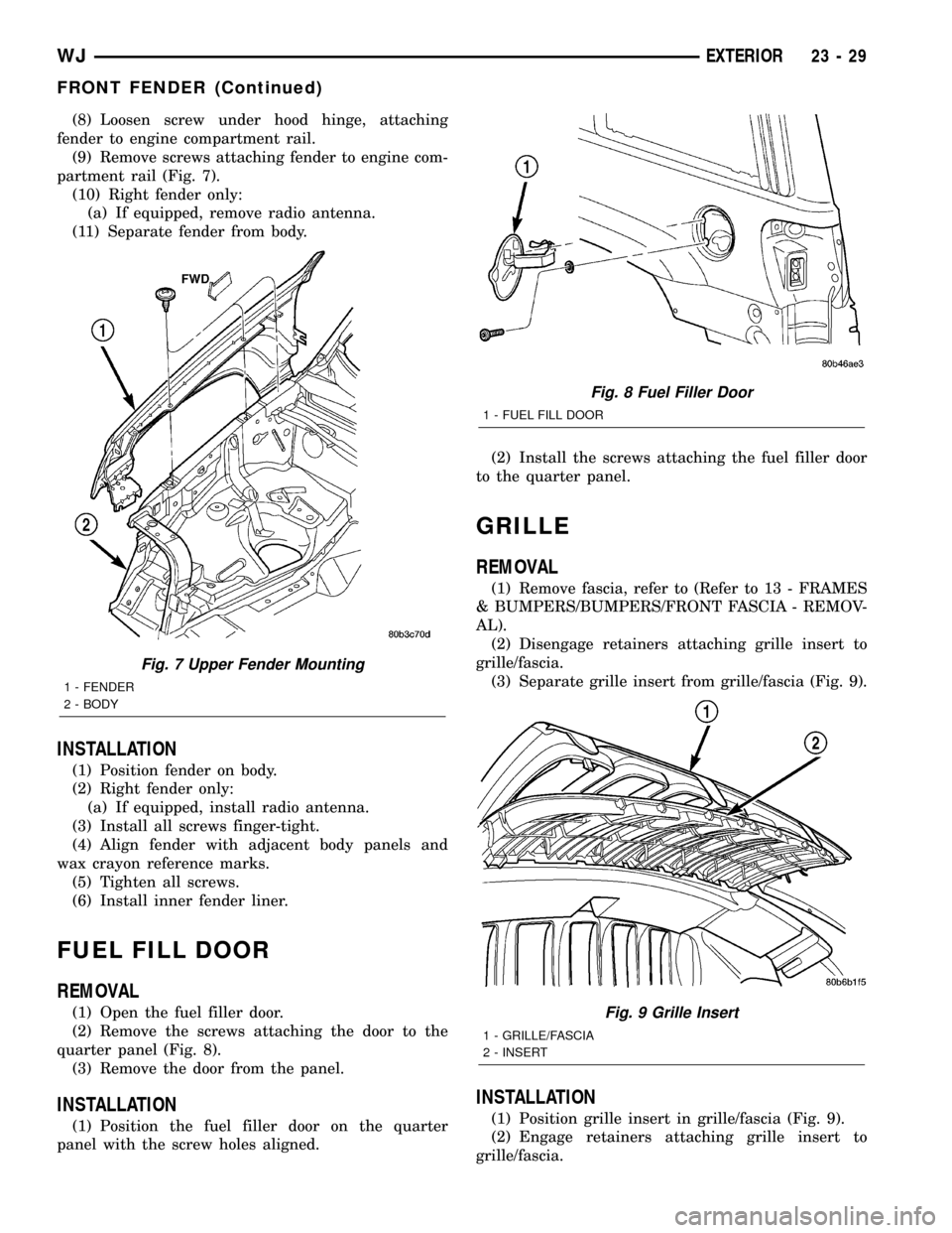
(8) Loosen screw under hood hinge, attaching
fender to engine compartment rail.
(9) Remove screws attaching fender to engine com-
partment rail (Fig. 7).
(10) Right fender only:
(a) If equipped, remove radio antenna.
(11) Separate fender from body.
INSTALLATION
(1) Position fender on body.
(2) Right fender only:
(a) If equipped, install radio antenna.
(3) Install all screws finger-tight.
(4) Align fender with adjacent body panels and
wax crayon reference marks.
(5) Tighten all screws.
(6) Install inner fender liner.
FUEL FILL DOOR
REMOVAL
(1) Open the fuel filler door.
(2) Remove the screws attaching the door to the
quarter panel (Fig. 8).
(3) Remove the door from the panel.
INSTALLATION
(1) Position the fuel filler door on the quarter
panel with the screw holes aligned.(2) Install the screws attaching the fuel filler door
to the quarter panel.
GRILLE
REMOVAL
(1) Remove fascia, refer to (Refer to 13 - FRAMES
& BUMPERS/BUMPERS/FRONT FASCIA - REMOV-
AL).
(2) Disengage retainers attaching grille insert to
grille/fascia.
(3) Separate grille insert from grille/fascia (Fig. 9).
INSTALLATION
(1) Position grille insert in grille/fascia (Fig. 9).
(2) Engage retainers attaching grille insert to
grille/fascia.
Fig. 7 Upper Fender Mounting
1 - FENDER
2 - BODY
Fig. 8 Fuel Filler Door
1 - FUEL FILL DOOR
Fig. 9 Grille Insert
1 - GRILLE/FASCIA
2 - INSERT
WJEXTERIOR 23 - 29
FRONT FENDER (Continued)