2003 JEEP GRAND CHEROKEE fluid
[x] Cancel search: fluidPage 1495 of 2199

ADJUSTMENTS
STEERING GEAR
NOTE: Adjusting the steering gear in the vehicle is
not recommended. Remove gear from the vehicle
and drain the fluid. Then mount gear in a vise to
perform adjustments.
OVER-CENTER
(1) Rotate the stub shaft with Socket 8343 from
stop to stop and count the number of turns.
(2) Center the stub shaft by rotating it from the
stop 1/2 of the total amount of turns.
(3) Place torque wrench and Socket 8343 in a ver-
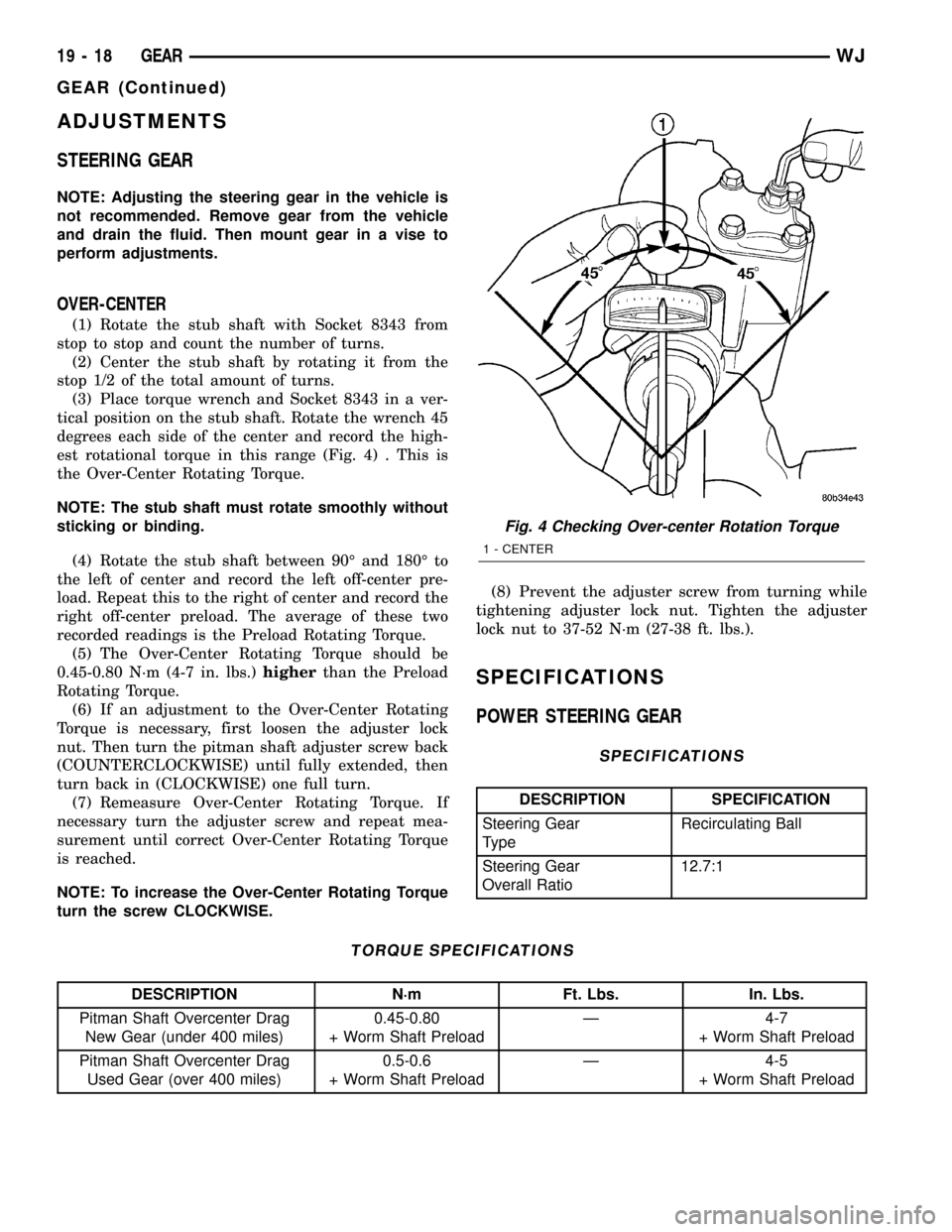
tical position on the stub shaft. Rotate the wrench 45
degrees each side of the center and record the high-
est rotational torque in this range (Fig. 4) . This is
the Over-Center Rotating Torque.
NOTE: The stub shaft must rotate smoothly without
sticking or binding.
(4) Rotate the stub shaft between 90É and 180É to
the left of center and record the left off-center pre-
load. Repeat this to the right of center and record the
right off-center preload. The average of these two
recorded readings is the Preload Rotating Torque.
(5) The Over-Center Rotating Torque should be
0.45-0.80 N´m (4-7 in. lbs.)higherthan the Preload
Rotating Torque.
(6) If an adjustment to the Over-Center Rotating
Torque is necessary, first loosen the adjuster lock
nut. Then turn the pitman shaft adjuster screw back
(COUNTERCLOCKWISE) until fully extended, then
turn back in (CLOCKWISE) one full turn.
(7) Remeasure Over-Center Rotating Torque. If
necessary turn the adjuster screw and repeat mea-
surement until correct Over-Center Rotating Torque
is reached.
NOTE: To increase the Over-Center Rotating Torque
turn the screw CLOCKWISE.(8) Prevent the adjuster screw from turning while
tightening adjuster lock nut. Tighten the adjuster
lock nut to 37-52 N´m (27-38 ft. lbs.).
SPECIFICATIONS
POWER STEERING GEAR
SPECIFICATIONS
DESCRIPTION SPECIFICATION
Steering Gear
TypeRecirculating Ball
Steering Gear
Overall Ratio12.7:1
TORQUE SPECIFICATIONS
DESCRIPTION N´m Ft. Lbs. In. Lbs.
Pitman Shaft Overcenter Drag
New Gear (under 400 miles)0.45-0.80
+ Worm Shaft PreloadÐ 4-7
+ Worm Shaft Preload
Pitman Shaft Overcenter Drag
Used Gear (over 400 miles)0.5-0.6
+ Worm Shaft PreloadÐ 4-5
+ Worm Shaft Preload
Fig. 4 Checking Over-center Rotation Torque
1 - CENTER
19 - 18 GEARWJ
GEAR (Continued)
Page 1502 of 2199

INSTALLATION
(1) Lubricate new o-ring and teflon rings with
power steering fluid and install on the rack piston/
valve assembly.
(2) Lubricate the rack piston/valve assembly with
power steering fluid.
(3) Slide the assembly into the gear housing.
(4) Install new stub shaft housing o-rings and
install the housing. Tighten the housing bolts to 62
N´m (46 ft. lbs.).
(5) Install new o-ring on the pitman shaft cover.
(6) Install the pitman shaft into the gear housing.
(7) Install the pitman shaft cover bolts and tighten
to 62 N´m (46 ft. lbs.).
(8) Perform over-center rotation torque adjustment
(Refer to 19 - STEERING/GEAR - ADJUSTMENTS)..
(9) Install the steering gear (Refer to 19 - STEER-
ING/GEAR - INSTALLATION).
(10) Fill the power steering pump (Refer to 19 -
STEERING/PUMP - STANDARD PROCEDURE).
STUB SHAFT HOUSING
REMOVAL
NOTE: If stub shaft housing, seal or bearing is dam-
aged the housing must be replaced.
(1) Remove the steering gear (Refer to 19 -
STEERING/GEAR - REMOVAL).
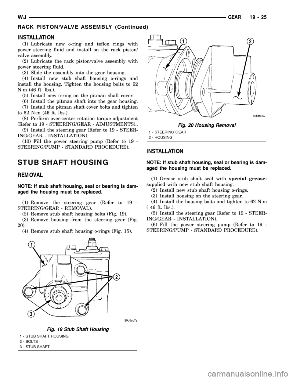
(2) Remove stub shaft housing bolts (Fig. 19).
(3) Remove housing from the steering gear (Fig.
20).
(4) Remove stub shaft housing o-rings (Fig. 15).
INSTALLATION
NOTE: If stub shaft housing, seal or bearing is dam-
aged the housing must be replaced.
(1) Grease stub shaft seal withspecial grease-
supplied with new stub shaft housing.
(2) Install new stub shaft housing o-rings.
(3) Install housing on the steering gear.
(4) Install the housing bolts and tighten to 62 N´m
( 46 ft. lbs.).
(5) Install the steering gear (Refer to 19 - STEER-
ING/GEAR - INSTALLATION).
(6) Fill the power steering pump (Refer to 19 -
STEERING/PUMP - STANDARD PROCEDURE).
Fig. 19 Stub Shaft Housing
1 - STUB SHAFT HOUSING
2 - BOLTS
3 - STUB SHAFT
Fig. 20 Housing Removal
1 - STEERING GEAR
2 - HOUSING
WJGEAR 19 - 25
RACK PISTON/VALVE ASSEMBLY (Continued)
Page 1508 of 2199

PUMP
TABLE OF CONTENTS
page page
PUMP
DESCRIPTION - 4.0L, 4.7L................32
OPERATION
OPERATION - 4.7L....................32
OPERATION - 4.0L....................32
DIAGNOSIS AND TESTING - PUMP LEAKAGE . 33
STANDARD PROCEDURE
STANDARD PROCEDURE - INITIAL
OPERATION - 4.0L....................33
STANDARD PROCEDURE - INITIAL
OPERATION - 4.7L....................33
REMOVAL
REMOVAL - 4.0L ENGINE...............34
REMOVAL - 4.7L ENGINE...............34
INSTALLATION
INSTALLATION - 4.0L ENGINE...........34
INSTALLATION - 4.7L ENGINE...........34
SPECIFICATIONS
TORQUE CHART......................35
SPECIAL TOOLS
POWER STEERING PUMP..............36
FLUID COOLER
DESCRIPTION.........................36
REMOVAL.............................36
INSTALLATION.........................37
HOSES - 4.0L
DESCRIPTION
DESCRIPTION - PRESSURE LINE........37
DESCRIPTION - RETURN LINE...........37
OPERATION
OPERATION - PRESSURE LINE..........37
OPERATION - RETURN LINE............37
REMOVAL.............................37
INSTALLATION.........................37
HOSES - 4.7L
DESCRIPTION
DESCRIPTION - 1/2º PRESSURE HOSE....38DESCRIPTION - 1/2º RETURN HOSE......38
DESCRIPTION - 3/8º PRESSURE HOSE....38
DESCRIPTION - 3/8º GEAR OUTLET HOSE . 38
DESCRIPTION - 3/8º RETURN HOSE......38
OPERATION
OPERATION - 1/2º PRESSURE HOSE......38
OPERATION - 1/2º RETURN HOSE........38
OPERATION - 3/8º PRESSURE HOSE......39
OPERATION - 3/8º GEAR OUTLET HOSE . . . 39
OPERATION - 3/8ºRETURN HOSE........39
REMOVAL
REMOVAL - 1/29PRESSURE HOSE.......39
REMOVAL - 1/29RETURN HOSE..........39
REMOVAL - 3/89PRESSURE HOSE.......39
REMOVAL - 3/89RETURN HOSE..........39
REMOVAL - 3/89GEAR OUTLET HOSE.....40
REMOVAL - INLET COOLER HOSE........40
REMOVAL - OUTLET COOLER HOSE......40
INSTALLATION
INSTALLATION - 1/29PRESSURE HOSE....40
INSTALLATION - 1/29RETURN HOSE......40
INSTALLATION - 3/89PRESSURE HOSE....41
INSTALLATION - 3/89RETURN HOSE......41
INSTALLATION - 3/89GEAR OUTLET HOSE . 41
INSTALLATION - INLET COOLER HOSE....41
INSTALLATION - OUTLET COOLER HOSE . . 41
PULLEY
DESCRIPTION
POWER STEERING PUMP PULLEY - 3.1L
DIESEL.............................41
REMOVAL.............................41
INSTALLATION.........................42
RESERVOIR
REMOVAL.............................42
INSTALLATION.........................42
WJPUMP 19 - 31
Page 1509 of 2199

PUMP
DESCRIPTION - 4.0L, 4.7L
Hydraulic pressure for the power steering system
is provided by a belt driven power steering pump
(Fig. 1) and (Fig. 2). The pump shaft has a
pressed-on drive pulley that is belt driven by the
crankshaft pulley.
OPERATION
OPERATION - 4.7L
The power steering pump is a constant flow rate
and displacement, vane-type pump. The pump has
internal parts that operate submerged in fluid. The
flow control orifice and the pressure relief valve,
which limits the pump pressure, are internal to the
pump. The reservoir is attached to the pump body
with spring clips. The power steering pump is used
to drive the hydraulic engine cooling fan, which sep-
arates the flow to the fan gerotors and the power
steering gear. The power steering pump is connected
to the engine cooling fan by pressure and return
hoses and the pump is connected to the steering gear
via a return hose from the steering cooler (Fig. 2).NOTE: Power steering pumps have different pres-
sure rates and are not interchangeable with other
pumps.OPERATION - 4.0L
The power steering pump is a constant flow rate
and displacement, vane-type pump. The pump inter-
nal parts operate submerged in fluid. The flow con-
trol orifice is part of the high pressure line fitting.
The pressure relief valve inside the flow control valve
limits the pump pressure. The reservoir is attached
to the pump body with spring clips. The power steer-
ing pump is connected to the steering gear by the
pressure and return hoses (Fig. 1).
NOTE: Power steering pumps have different pres-
sure rates and are not interchangeable with other
pumps.
Fig. 1 Pump With Integral Reservoir
1 - CAP
2 - FLUID RESERVOIR (TYPICAL)
3 - HIGH-PRESSURE FITTING
4 - DRIVE PULLEY
5 - PUMP BODY
6 - RESERVOIR CLIP
Fig. 2 4.7L POWER STEERING PUMP
1 - PRESSURE HOSE QUICK CONNECT NUT
2 - CAP
3 - FLUID RESERVOIR
4 - LOW-PRESSURE RETURN FROM THE COOLER
5 - LOW-PRESSURE RETURN FROM THE HYDRAULIC FAN
DRIVE
6 - PUMP BODY
7 - HIGH PRESSURE FITTING
19 - 32 PUMPWJ
Page 1510 of 2199

DIAGNOSIS AND TESTING - PUMP LEAKAGE
(1) Possible areas of pump leakage (Fig. 3).
STANDARD PROCEDURE
STANDARD PROCEDURE - INITIAL OPERATION
- 4.0L
WARNING: THE FLUID LEVEL SHOULD BE
CHECKED WITH ENGINE OFF TO PREVENT INJURY
FROM MOVING COMPONENTS.
CAUTION: Use MOPAR Power Steering Fluid or
equivalent. Do not use automatic transmission fluid
and do not overfill.
Wipe filler cap clean, then check the fluid level.
The dipstick should indicateCOLDwhen the fluid is
at normal ambient temperature.
(1) Fill the pump fluid reservoir to the proper level
and let the fluid settle for at least two minutes.
(2) Start the engine and let run for a few seconds
then turn engine off.
(3) Add fluid if necessary. Repeat the above proce-
dure until the fluid level remains constant after run-
ning the engine.
(4) Raise the front wheels off the ground.
(5) Slowly turn the steering wheel right and left,
lightly contacting the wheel stops at least 20 times.(6) Check the fluid level add if necessary.
(7) Lower the vehicle, start the engine and turn
the steering wheel slowly from lock to lock.
(8) Stop the engine and check the fluid level and
refill as required.
(9) If the fluid is extremely foamy or milky look-
ing, allow the vehicle to stand a few minutes and
repeat the procedure.
CAUTION: Do not run a vehicle with foamy fluid for
an extended period. This may cause pump damage.
STANDARD PROCEDURE - INITIAL OPERATION
- 4.7L
WARNING: THE FLUID LEVEL SHOULD BE
CHECKED WITH ENGINE OFF TO PREVENT INJURY
FROM MOVING COMPONENTS.
NOTE: Remove as much of the old fluid out of the
system as possible with a suction tool or by remov-
ing a hose, When a component has failed. Then
refill it with fresh fluid until it is clean. This may
have to be done more than once.
CAUTION: Use MOPAR Power Steering Fluid or
equivalent. Do not use automatic transmission fluid
and do not overfill.
Wipe filler cap clean, then check the fluid level.
The dipstick should indicateCOLDwhen the fluid is
at normal ambient temperature.
(1) Fill the pump fluid reservoir to the proper level
and let the fluid settle for at least two minutes.
(2) Start the engine and let run for a few seconds
then turn engine off.
(3) Add fluid if necessary. Repeat the above proce-
dure until the fluid level remains constant after run-
ning the engine.
(4) Raise the front wheels off the ground.
(5) Slowly turn the steering wheel right and left,
lightly contacting the wheel stops at least 20 times.
(6) Check the fluid level add if necessary.
(7) Lower the vehicle, start the engine, and use
the DRB III to activate the hydraulic fan on full fan
operation.
(8)
Turn the steering wheel slowly from lock to lock.
(9) Stop the engine, check the fluid level and refill
as required and repeat the process
CAUTION: Do not run a vehicle with foamy fluid for
an extended period. This may cause pump damage.
(10) If the fluid is extremely foamy or milky look-
ing, allow the vehicle to stand a few minutes and
repeat the procedure.
Fig. 3 4.0L Power Steering Pump
WJPUMP 19 - 33
PUMP (Continued)
Page 1511 of 2199

(11) While the vehicle is in park, use the DRB III
to activate the hydraulic fan to full fan operation and
briefly rev the engine up to 3000 rpm to fully engage
the hydraulic fan.
(12) Check the fluid level add if necessary.
REMOVAL
REMOVAL - 4.0L ENGINE
(1) Remove serpentine drive belt,(Refer to 7 -
COOLING/ACCESSORY DRIVE/DRIVE BELTS -
REMOVAL).
(2) Remove pressure and return hoses from pump
and drain the pump.
(3)
Loosen the pump bracket bolt at the engine block.
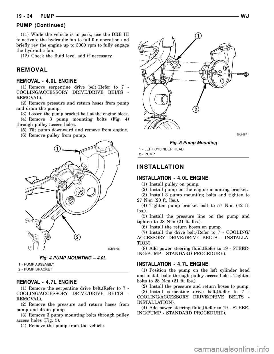
(4) Remove 3 pump mounting bolts (Fig. 4)
through pulley access holes.
(5) Tilt pump downward and remove from engine.
(6) Remove pulley from pump.
REMOVAL - 4.7L ENGINE
(1) Remove the serpentine drive belt,(Refer to 7 -
COOLING/ACCESSORY DRIVE/DRIVE BELTS -
REMOVAL).
(2) Remove the pressure and return hoses from
pump and drain pump.
(3) Remove 3 pump mounting bolts through pulley
access holes (Fig. 5).
(4) Remove the pump from the vehicle.
INSTALLATION
INSTALLATION - 4.0L ENGINE
(1) Install pulley on pump.
(2) Install pump on the engine mounting bracket.
(3) Install 3 pump mounting bolts and tighten to
27 N´m (20 ft. lbs.).
(4) Tighten pump bracket bolt to 57 N´m (42 ft.
lbs.).
(5) Install the pressure line on the pump and
tighten to 28 N´m (21 ft. lbs.).
(6) Install the return hoses on pump.
(7) Install the drive belt,(Refer to 7 - COOLING/
ACCESSORY DRIVE/DRIVE BELTS - INSTALLA-
TION).
(8) Add power steering fluid,(Refer to 19 - STEER-
ING/PUMP - STANDARD PROCEDURE).
INSTALLATION - 4.7L ENGINE
(1) Position the pump on the left cylinder head
and install bolts through pulley access holes. Tighten
bolts to 28 N´m (21 ft. lbs.).
(2) Install the pressure and return hoses to pump.
(3) Install serpentine drive belt,(Refer to 7 -
COOLING/ACCESSORY DRIVE/DRIVE BELTS -
INSTALLATION).
(4) Add power steering fluid,(Refer to 19 - STEER-
ING/PUMP - STANDARD PROCEDURE).
Fig. 4 PUMP MOUNTING ± 4.0L
1 - PUMP ASSEMBLY
2 - PUMP BRACKET
Fig. 5 Pump Mounting
1 - LEFT CYLINDER HEAD
2 - PUMP
19 - 34 PUMPWJ
PUMP (Continued)
Page 1513 of 2199

SPECIAL TOOLS
POWER STEERING PUMP
FLUID COOLER
DESCRIPTION
4.7L models of this vehicle are equipped with a
cooler for the power steering system fluid. The power
steering fluid cooler is located at the front of the
vehicle. It is mounted to the radiator support just
forward of the air-conditioning condenser and just
rearward of the front fascia (Fig. 6). The cooler is
positioned so it is in the air flow through the front
fascia of the vehicle.
REMOVAL
(1) Disconnect negative battery cable at battery.
(2) Drain the power steering fluid out of the reser-
voir.
(3) Remove the front fascia grille assembly,(Refer
to 13 - FRAMES & BUMPERS/BUMPERS/FRONT
FASCIA - REMOVAL).
(4) Remove the grille opening reinforcement panel
(5) Place a drain pan under the cooler.
(6) Disconnect the lower hose at cooler (Fig. 6).
(7) Disconnect the upper hose at cooler (Fig. 6).
(8) Remove the three cooler mounting bolts (Fig.
6).
(9) Remove the cooler from the vehicle.
Analyzer Set, Power Steering Flow/Pressure 6815
Adapters, Power Steering Flow/Pressure Tester
6893
4.7L HYDRAULIC POWER STEERING TEST
ADAPTER KIT - 8630
Puller C-4333
Installer, Power Steering Pulley C-4063B
Fig. 6 POWER STEERING FLUID COOLER
1 - POWER STEERING COOLER
2 - POWER STEERING COOLER LINES CLIP
19 - 36 PUMPWJ
PUMP (Continued)
Page 1514 of 2199

INSTALLATION
(1) Position and install the power steering cooler
to the vehicle.
(2) Install the three mounting bracket bolts (Fig.
6).
(3) Reconnect the upper hose at cooler (Fig. 6).
(4) Reconnect the lower hose at cooler (Fig. 6).
(5) Connect negative battery cable to battery.
(6) Refill the power steering fluid and bleed the
system,(Refer to 19 - STEERING/PUMP - STAN-
DARD PROCEDURE).
(7) Start engine and check for leaks.
(8) Install the grille opening reinforcement panel
(9) Install the front fascia grille,(Refer to 13 -
FRAMES & BUMPERS/BUMPERS/FRONT FASCIA
- INSTALLATION).
HOSES - 4.0L
DESCRIPTION
DESCRIPTION - PRESSURE LINE
The hose consists of two metal ends and rubber
center section that contains a tuning cable. The
pump end uses a quick connect fitting. Lubircation
must be used on the quick connect nut and o-ring
when installing.
DESCRIPTION - RETURN LINE
Power steering return line is a hose which is
clamped at the pump and the gear.
OPERATION
OPERATION - PRESSURE LINE
Power steering pressure line, is used to transfer
high pressure power steering fluid, from the power
steering pump to the power steering gear on the
4.0L. The 4.7L power steering pressure line, is used
to transfer high pressure power steering fluid, from
the power steering pump to the engine cooling fan
and the steering gear.
OPERATION - RETURN LINE
Power steering return line, is used to transfer low
pressure power steering fluid, from the power steer-
ing gear to the power steering pump.
REMOVAL
(1) Drain the power steering fluid from the reser-
voir.
(2) Remove the air box,(Refer to 9 - ENGINE/AIR
INTAKE SYSTEM/AIR CLEANER HOUSING -
REMOVAL).
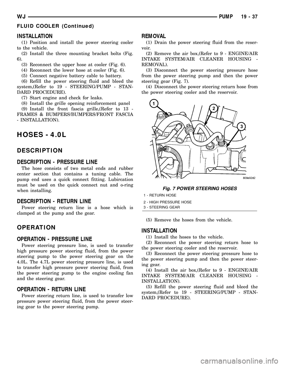
(3) Disconnect the power steering pressure hose
from the power steering pump and then the power
steering gear (Fig. 7).
(4) Disconnect the power steering return hose from
the power steering cooler and the reservoir.
(5) Remove the hoses from the vehicle.
INSTALLATION
(1) Install the hoses to the vehicle.
(2) Reconnect the power steering return hose to
the power steering cooler and the reservoir.
(3) Reconnect the power steering pressure hose to
the power steering pump and then the power steer-
ing gear.
(4) Install the air box,(Refer to 9 - ENGINE/AIR
INTAKE SYSTEM/AIR CLEANER HOUSING -
INSTALLATION).
(5) Refill the power steering fluid and bleed the
system,(Refer to 19 - STEERING/PUMP - STAN-
DARD PROCEDURE).
Fig. 7 POWER STEERING HOSES
1 - RETURN HOSE
2 - HIGH PRESSURE HOSE
3 - STEERING GEAR
WJPUMP 19 - 37
FLUID COOLER (Continued)