Page 31 of 2199

ing (Fig. 4) from the steering knuckle and off the
axle shaft.
INSTALLATION
(1) Install the hub bearing to the knuckle.
(2) Install the hub bearing to knuckle bolts and
tighten to 102 N´m (75 ft. lbs.).
(3) Install the hub washer and nut. Tighten the
hub nut to 237 N´m (175 ft. lbs.). Install the nut
retainer and a new cotter pin.
(4) Install the brake rotor, caliper anchor, caliper
and ABS wheel speed sensor,(Refer to 5 - BRAKES/
ELECTRICAL/FRONT WHEEL SPEED SENSOR -
INSTALLATION).
(5) Install the wheel and tire assembly (Refer to 22
- TIRES/WHEELS - STANDARD PROCEDURE).
(6) Remove the support and lower the vehicle.
KNUCKLE
DESCRIPTION
The knuckle is a single casting with legs machined
for the upper and lower ball joints. The knuckle also
has machined mounting locations for the front brake
calipers and hub bearing.
OPERATION
The steering knuckle pivot between the upper and
lower ball joint. Steering linkage attached to the
knuckle allows the vehicle to be steered.
REMOVAL - STEERING KNUCKLE
Ball stud service procedures below require removal
of the hub bearing and axle shaft. Removal andinstallation of upper and lower ball studs require the
use of Tool Kit 6289.
(1) Remove hub bearing and axle shaft.
(2) Disconnect the tie-rod or drag link from the
steering knuckle arm,(Refer to 19 - STEERING/
LINKAGE/TIE ROD END - REMOVAL) .
(3) Remove the cotter pins from the upper and
lower ball studs.
(4) Remove the upper and lower ball stud nuts.
(5) Strike the steering knuckle with a brass ham-
mer to loosen knuckle from the ball studs. Remove
knuckle from ball studs (Fig. 5).
INSTALLATION
(1) Position the steering knuckle on the ball studs.
(2) Install and tighten the bottom retaining nut to
109 N´m (80 ft. lbs.) torque. Install new cotter pin.
(3) Install and tighten the top retaining nut to 101
N´m (75 ft. lbs.) torque. Install new cotter pin.
(4) Install the hub bearing and axle shaft.
(5) Connect the tie-rod or drag link end to the
steering knuckle arm.,(Refer to 19 - STEERING/
LINKAGE/TIE ROD END - INSTALLATION) .
Fig. 4 Hub Bearing & Knuckle
1 - HUB BEARING
2 - KNUCKLE
Fig. 5 Steering Knuckle Removal/Installation
1 - AXLE YOKE
2 - UPPER BALL STUD
3 - LOWER BALL STUD
4 - STEERING KNUCKLE
2 - 10 FRONTWJ
HUB / BEARING (Continued)
Page 1398 of 2199

EXHAUST SYSTEM
TABLE OF CONTENTS
page page
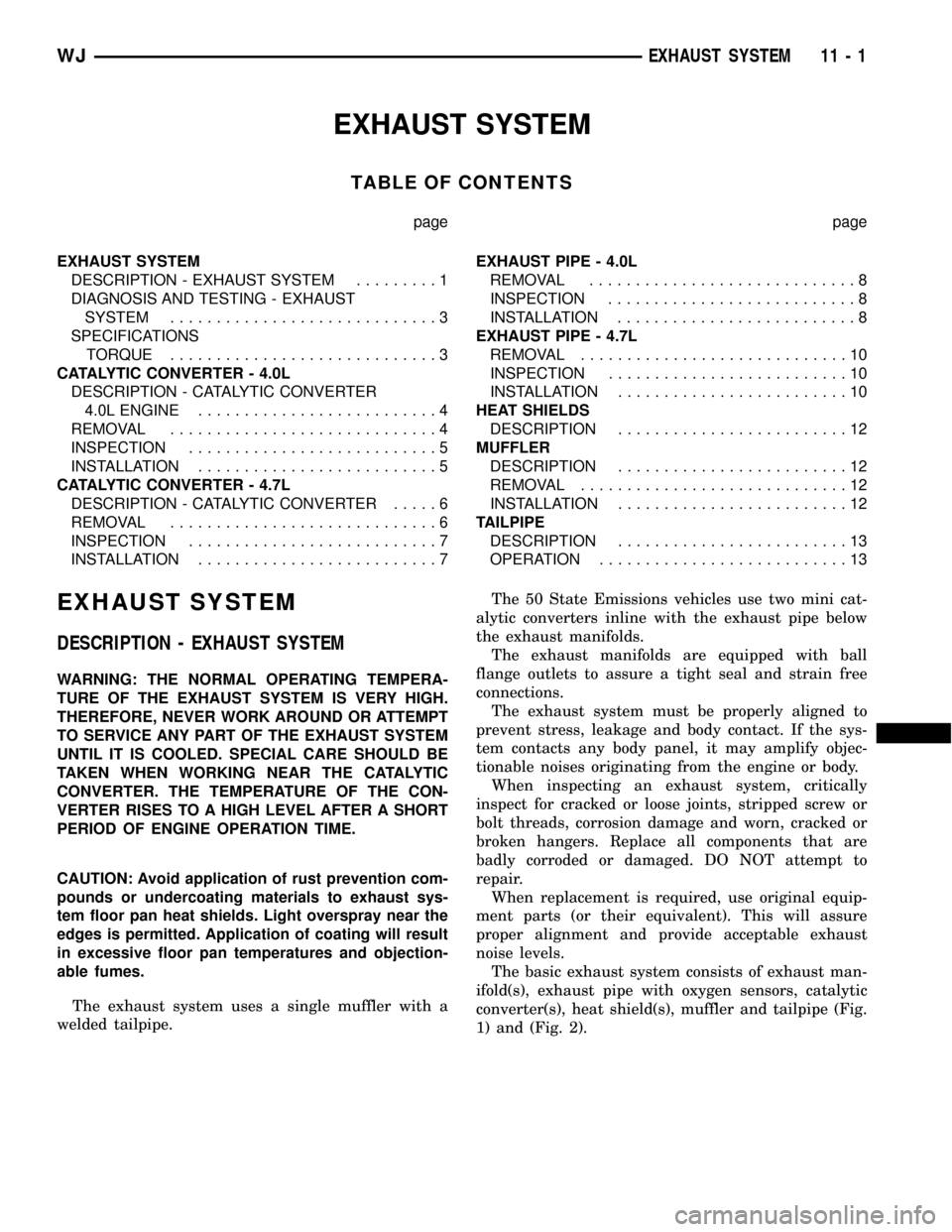
EXHAUST SYSTEM
DESCRIPTION - EXHAUST SYSTEM.........1
DIAGNOSIS AND TESTING - EXHAUST
SYSTEM.............................3
SPECIFICATIONS
TORQUE.............................3
CATALYTIC CONVERTER - 4.0L
DESCRIPTION - CATALYTIC CONVERTER
4.0L ENGINE..........................4
REMOVAL.............................4
INSPECTION...........................5
INSTALLATION..........................5
CATALYTIC CONVERTER - 4.7L
DESCRIPTION - CATALYTIC CONVERTER.....6
REMOVAL.............................6
INSPECTION...........................7
INSTALLATION..........................7EXHAUST PIPE - 4.0L
REMOVAL.............................8
INSPECTION...........................8
INSTALLATION..........................8
EXHAUST PIPE - 4.7L
REMOVAL.............................10
INSPECTION..........................10
INSTALLATION.........................10
HEAT SHIELDS
DESCRIPTION.........................12
MUFFLER
DESCRIPTION.........................12
REMOVAL.............................12
INSTALLATION.........................12
TAILPIPE
DESCRIPTION.........................13
OPERATION...........................13
EXHAUST SYSTEM
DESCRIPTION - EXHAUST SYSTEM
WARNING: THE NORMAL OPERATING TEMPERA-
TURE OF THE EXHAUST SYSTEM IS VERY HIGH.
THEREFORE, NEVER WORK AROUND OR ATTEMPT
TO SERVICE ANY PART OF THE EXHAUST SYSTEM
UNTIL IT IS COOLED. SPECIAL CARE SHOULD BE
TAKEN WHEN WORKING NEAR THE CATALYTIC
CONVERTER. THE TEMPERATURE OF THE CON-
VERTER RISES TO A HIGH LEVEL AFTER A SHORT
PERIOD OF ENGINE OPERATION TIME.
CAUTION: Avoid application of rust prevention com-
pounds or undercoating materials to exhaust sys-
tem floor pan heat shields. Light overspray near the
edges is permitted. Application of coating will result
in excessive floor pan temperatures and objection-
able fumes.
The exhaust system uses a single muffler with a
welded tailpipe.The 50 State Emissions vehicles use two mini cat-
alytic converters inline with the exhaust pipe below
the exhaust manifolds.
The exhaust manifolds are equipped with ball
flange outlets to assure a tight seal and strain free
connections.
The exhaust system must be properly aligned to
prevent stress, leakage and body contact. If the sys-
tem contacts any body panel, it may amplify objec-
tionable noises originating from the engine or body.
When inspecting an exhaust system, critically
inspect for cracked or loose joints, stripped screw or
bolt threads, corrosion damage and worn, cracked or
broken hangers. Replace all components that are
badly corroded or damaged. DO NOT attempt to
repair.
When replacement is required, use original equip-
ment parts (or their equivalent). This will assure
proper alignment and provide acceptable exhaust
noise levels.
The basic exhaust system consists of exhaust man-
ifold(s), exhaust pipe with oxygen sensors, catalytic
converter(s), heat shield(s), muffler and tailpipe (Fig.
1) and (Fig. 2).
WJEXHAUST SYSTEM 11 - 1
Page 1480 of 2199

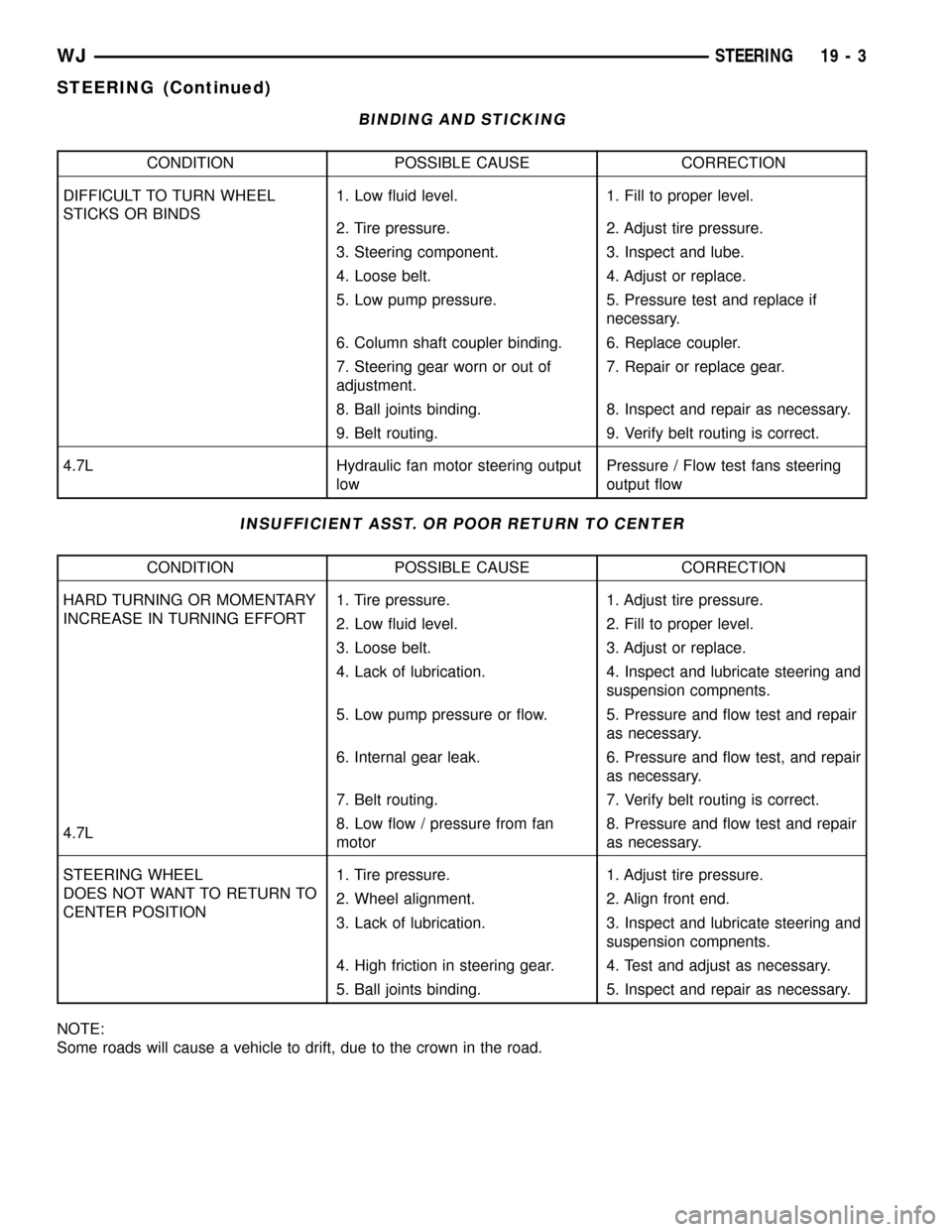
BINDING AND STICKING
CONDITION POSSIBLE CAUSE CORRECTION
DIFFICULT TO TURN WHEEL
STICKS OR BINDS1. Low fluid level. 1. Fill to proper level.
2. Tire pressure. 2. Adjust tire pressure.
3. Steering component. 3. Inspect and lube.
4. Loose belt. 4. Adjust or replace.
5. Low pump pressure. 5. Pressure test and replace if
necessary.
6. Column shaft coupler binding. 6. Replace coupler.
7. Steering gear worn or out of
adjustment.7. Repair or replace gear.
8. Ball joints binding. 8. Inspect and repair as necessary.
9. Belt routing. 9. Verify belt routing is correct.
4.7L Hydraulic fan motor steering output
lowPressure / Flow test fans steering
output flow
INSUFFICIENT ASST. OR POOR RETURN TO CENTER
CONDITION POSSIBLE CAUSE CORRECTION
HARD TURNING OR MOMENTARY
INCREASE IN TURNING EFFORT1. Tire pressure. 1. Adjust tire pressure.
2. Low fluid level. 2. Fill to proper level.
3. Loose belt. 3. Adjust or replace.
4. Lack of lubrication. 4. Inspect and lubricate steering and
suspension compnents.
5. Low pump pressure or flow. 5. Pressure and flow test and repair
as necessary.
6. Internal gear leak. 6. Pressure and flow test, and repair
as necessary.
7. Belt routing. 7. Verify belt routing is correct.
4.7L8. Low flow / pressure from fan
motor8. Pressure and flow test and repair
as necessary.
STEERING WHEEL
DOES NOT WANT TO RETURN TO
CENTER POSITION1. Tire pressure. 1. Adjust tire pressure.
2. Wheel alignment. 2. Align front end.
3. Lack of lubrication. 3. Inspect and lubricate steering and
suspension compnents.
4. High friction in steering gear. 4. Test and adjust as necessary.
5. Ball joints binding. 5. Inspect and repair as necessary.
NOTE:
Some roads will cause a vehicle to drift, due to the crown in the road.
WJSTEERING 19 - 3
STEERING (Continued)