2003 JEEP GRAND CHEROKEE Tools
[x] Cancel search: ToolsPage 1769 of 2199

(5) Refill the transmission to proper level.
DISASSEMBLY
(1) Remove the bolts holding the reaction shaft
support to the oil pump (Fig. 91).
(2) Remove the reaction shaft support from the oil
pump (Fig. 91).
(3) Remove all bolts holding the oil pump halves
together (Fig. 91).(4) Using suitable prying tools, separate the oil
pump sections by inserting the tools in the supplied
areas and prying the halves apart.
NOTE: The oil pump halves are aligned to each
other through the use of two dowels. Be sure to pry
upward evenly to prevent damage to the oil pump
components.
Fig. 91 Oil Pump Assembly
1 - PUMP HOUSING 4 - SEAL RING (5)
2 - SEAL 5 - REACTION SHAFT SUPPORT
3 - OIL FILTER SEAL 6 - PUMP VALVE BODY
21 - 250 AUTOMATIC TRANSMISSION - 545RFEWJ
OIL PUMP (Continued)
Page 1799 of 2199

TRANSFER CASE - NV242
TABLE OF CONTENTS
page page
TRANSFER CASE - NV242
DESCRIPTION........................280
OPERATION..........................281
DIAGNOSIS AND TESTING - TRANSFER
CASE - NV242.......................281
REMOVAL............................282
DISASSEMBLY........................282
CLEANING...........................292
INSPECTION.........................293
ASSEMBLY...........................295
INSTALLATION........................307
SPECIFICATIONS
TRANSFER CASE - NV242.............308
SPECIAL TOOLS
TRANSFER CASE - NV242.............308
FLUID
STANDARD PROCEDURE - FLUID DRAIN/
REFILL............................310FRONT OUTPUT SHAFT SEAL
REMOVAL............................310
INSTALLATION........................310
POSITION SENSOR
DESCRIPTION........................311
OPERATION..........................311
REMOVAL............................312
INSTALLATION........................312
REAR RETAINER BUSHING AND SEAL -
NV242HD
REMOVAL............................312
INSTALLATION........................312
SHIFT CABLE
REMOVAL............................313
INSTALLATION........................313
TRANSFER CASE - NV242
DESCRIPTION
The NV242 is a full transfer case (Fig. 1). It pro-
vides full time 2-wheel, or 4-wheel drive operation.
A differential in the transfer case is used to control
torque transfer to the front and rear axles. A low
range gear provides increased low speed torque capa-
bility for off road operation. The low range provides a
2.72:1 reduction ratio.
The geartrain is mounted in two aluminum case
halves attached with bolts. The mainshaft front and
rear bearings are mounted in aluminum retainer
housings bolted to the case halves.
TRANSFER CASE IDENTIFICATION
Two versions of the NV242 are used in the WJ
vehicles, NV242LD and NV242HD. The two transfer
cases can be distinguished from one another by the
rear output shaft retainer. The NV242LD uses a rub-
ber boot to cover the rear output shaft, while the
NV242HD uses a cast aluminum housing. Other than
this difference, the two transfer cases are serviced
the same.
A circular ID tag is attached to the rear case of
each transfer case (Fig. 2). The ID tag provides the
transfer case model number, assembly number, serial
number, and low range ratio.The transfer case serial number also represents
the date of build.
SHIFT MECHANISM
Operating ranges are selected with a lever in the
floor mounted shifter assembly. The shift lever is con-
nected to the transfer case range lever by an adjust-
able cable. A straight line shift pattern is used.
Range positions are marked on the shifter bezel.
Fig. 1 NV242 Transfer Case
21 - 280 TRANSFER CASE - NV242WJ
Page 1827 of 2199

SPECIFICATIONS
TRANSFER CASE - NV242
TORQUE SPECIFICATIONS
DESCRIPTION N´m Ft. Lbs. In. Lbs.
Plug, Detent 16-24 11.8-17.7 -
Bolt, Diff. Case 17-27 12.5-19.9 -
Plug, Drain/Fill 20-34 15-25 -
Bolt, Front Brg. Retainer 16-27 11.8-19.9 -
Bolt, Case Half 35-46 25.8-33.9 -
Nut, Front Yoke 122-176 90-130 -
Screw, Oil Pump 1.2-1.8 - 12-15
Nut, Range Lever 27-34 19.9-25 -
Bolt, Rear Retainer 35-46 25.8-33.9 -
Nuts, Mounting 35 25.8 -
Bolts, U-Joint 19 14 -
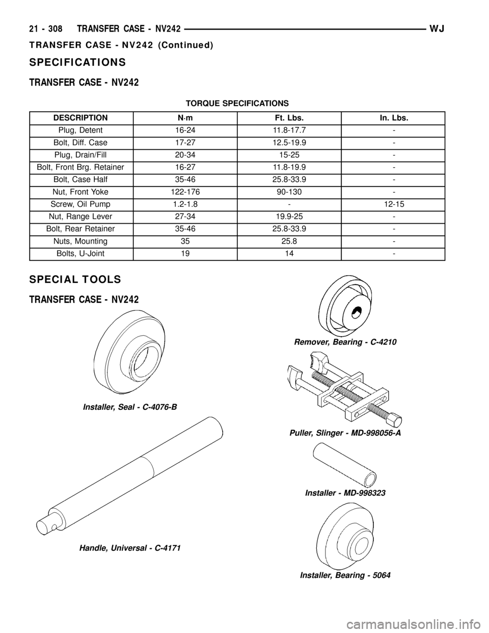
SPECIAL TOOLS
TRANSFER CASE - NV242
Installer, Seal - C-4076-B
Handle, Universal - C-4171
Remover, Bearing - C-4210
Puller, Slinger - MD-998056-A
Installer - MD-998323
Installer, Bearing - 5064
21 - 308 TRANSFER CASE - NV242WJ
TRANSFER CASE - NV242 (Continued)
Page 1834 of 2199

TRANSFER CASE - NV247
TABLE OF CONTENTS
page page
TRANSFER CASE - NV247
DESCRIPTION........................315
OPERATION..........................316
DIAGNOSIS AND TESTING - TRANSFER
CASE - NV247.......................316
REMOVAL............................317
DISASSEMBLY........................317
CLEANING...........................324
INSPECTION.........................324
ASSEMBLY...........................326
INSTALLATION........................335
SPECIFICATIONS
TRANSFER CASE - NV247.............336
SPECIAL TOOLS
TRANSFER CASE - NV247.............337FLUID
STANDARD PROCEDURE - FLUID DRAIN/
REFILL............................338
FRONT OUTPUT SHAFT SEAL
REMOVAL............................338
INSTALLATION........................338
REAR RETAINER BUSHING AND SEAL
REMOVAL............................339
INSTALLATION........................339
SHIFT CABLE
REMOVAL............................340
INSTALLATION........................340
TRANSFER CASE - NV247
DESCRIPTION
The NV247 (Fig. 1) is an on-demand 4-wheel drive
transfer case with two operating ranges and a neu-
tral position. Operating ranges are 4-high and 4-low.
The 4-low range is used for extra pulling power in
off-road situations.
TRANSFER CASE IDENTIFICATION
A circular I.D. tag is attached to the rear case of
each NV247 transfer case (Fig. 2). The tag indicates
the following information:
²Model number
²Serial number
²Assembly number
²Gear ratio
²Location of manufacture
The transfer case serial number also represents
the date of build.
Fig. 1 NV247 Transfer Case
Fig. 2 Transfer Case I.D. Tag
1 - FILL PLUG
2 - I.D. TAG
3 - DRAIN PLUG
WJTRANSFER CASE - NV247 21 - 315
Page 1856 of 2199

SPECIAL TOOLS
TRANSFER CASE - NV247
Installer, Bearing - 5066
Installer, Seal - 6952-A
Installer, Bearing - 6953
Remover, Bushing - 6957
Installer, Seal - C-3995-A
Handle - C-4171
Installer, Bushing - 8145
Remover, Bearing - C-4210
Remover, Bearing - L-4454
Cup - 8148
WJTRANSFER CASE - NV247 21 - 337
TRANSFER CASE - NV247 (Continued)
Page 1867 of 2199

DIAGNOSIS AND TESTING
DIAGNOSIS AND TESTING - PRESSURE
GAUGES
A quality air pressure gauge is recommended to
check tire pressure. After checking the air pressure,
replace valve cap finger tight.
DIAGNOSIS AND TESTING - TREAD WEAR
INDICATORS
Tread wear indicators are molded into the bottom
of the tread grooves. When tread depth is 1.6 mm
(1/16 in.), the tread wear indicators will appear as a
13 mm (1/2 in.) band (Fig. 15).
Tire replacement is necessary when indicators
appear in two or more grooves or if localized balding
occurs.
DIAGNOSIS AND TESTING - TIRE WEAR
PATTERNS
Under inflation will cause wear on the shoulders of
tire. Over inflation will cause wear at the center of
tire.
Excessive camber causes the tire to run at an
angle to the road. One side of tread is then worn
more than the other (Fig. 16).
Excessive toe-in or toe-out causes wear on the
tread edges and a feathered effect across the tread
(Fig. 16).
DIAGNOSIS AND TESTING - TIRE NOISE OR
VIBRATION
Radial-ply tires are sensitive to force impulses
caused by improper mounting, vibration, wheel
defects, or possibly tire imbalance.
To find out if tires are causing the noise or vibra-
tion, drive the vehicle over a smooth road at varying
speeds. Note the noise level during acceleration and
deceleration. The engine, differential and exhaust
noises will change as speed varies, while the tire
noise will usually remain constant.
STANDARD PROCEDURE - REPAIRING LEAKS
For proper repairing, a radial tire must be removed
from the wheel. Repairs should only be made if the
defect, or puncture, is in the tread area (Fig. 17). The
tire should be replaced if the puncture is located in
the sidewall.
Deflate tire completely before removing the tire
from the wheel. Use lubrication such as a mild soap
solution when dismounting or mounting tire. Use
tools free of burrs or sharp edges which could dam-
age the tire or wheel rim.
Before mounting tire on wheel, make sure all rust
is removed from the rim bead and repaint if neces-
sary.
Install wheel on vehicle, and tighten to proper
torque specification (Refer to 22 - TIRES/WHEELS/
WHEELS - SPECIFICATIONS).
Fig. 15 Tread Wear Indicators
1 - TREAD ACCEPTABLE
2 - TREAD UNACCEPTABLE
3 - WEAR INDICATOR
22 - 8 TIRES/WHEELSWJ
Page 1874 of 2199

BODY
TABLE OF CONTENTS
page page
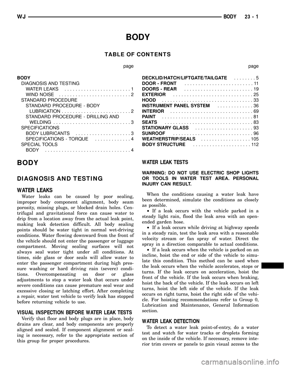
BODY
DIAGNOSIS AND TESTING
WATER LEAKS........................1
WIND NOISE..........................2
STANDARD PROCEDURE
STANDARD PROCEDURE - BODY
LUBRICATION.........................2
STANDARD PROCEDURE - DRILLING AND
WELDING............................3
SPECIFICATIONS
BODY LUBRICANTS....................3
SPECIFICATIONS - TORQUE.............4
SPECIAL TOOLS
BODY...............................4DECKLID/HATCH/LIFTGATE/TAILGATE........5
DOOR - FRONT.........................11
DOORS - REAR.........................19
EXTERIOR.............................25
HOOD.................................33
INSTRUMENT PANEL SYSTEM.............36
INTERIOR..............................69
PAINT.................................81
SEATS................................83
STATIONARY GLASS.....................93
SUNROOF.............................96
WEATHERSTRIP/SEALS..................105
BODY STRUCTURE.....................112
BODY
DIAGNOSIS AND TESTING
WATER LEAKS
Water leaks can be caused by poor sealing,
improper body component alignment, body seam
porosity, missing plugs, or blocked drain holes. Cen-
trifugal and gravitational force can cause water to
drip from a location away from the actual leak point,
making leak detection difficult. All body sealing
points should be water tight in normal wet-driving
conditions. Water flowing downward from the front of
the vehicle should not enter the passenger or luggage
compartment. Moving sealing surfaces will not
always seal water tight under all conditions. At
times, side glass or door seals will allow water to
enter the passenger compartment during high pres-
sure washing or hard driving rain (severe) condi-
tions. Overcompensating on door or glass
adjustments to stop a water leak that occurs under
severe conditions can cause premature seal wear and
excessive closing or latching effort. After completing
a repair, water test vehicle to verify leak has stopped
before returning vehicle to use.
VISUAL INSPECTION BEFORE WATER LEAK TESTS
Verify that floor and body plugs are in place, body
drains are clear, and body components are properly
aligned and sealed. If component alignment or seal-
ing is necessary, refer to the appropriate section of
this group for proper procedures.
WATER LEAK TESTS
WARNING: DO NOT USE ELECTRIC SHOP LIGHTS
OR TOOLS IN WATER TEST AREA. PERSONAL
INJURY CAN RESULT.
When the conditions causing a water leak have
been determined, simulate the conditions as closely
as possible.
²If a leak occurs with the vehicle parked in a
steady light rain, flood the leak area with an open-
ended garden hose.
²If a leak occurs while driving at highway speeds
in a steady rain, test the leak area with a reasonable
velocity stream or fan spray of water. Direct the
spray in a direction comparable to actual conditions.
²If a leak occurs when the vehicle is parked on an
incline, hoist the end or side of the vehicle to simu-
late this condition. This method can be used when
the leak occurs when the vehicle accelerates, stops or
turns. If the leak occurs on acceleration, hoist the
front of the vehicle. If the leak occurs when braking,
hoist the back of the vehicle. If the leak occurs on left
turns, hoist the left side of the vehicle. If the leak
occurs on right turns, hoist the right side of the vehi-
cle. For hoisting recommendations refer to Group 0,
Lubrication and Maintenance, General Information
section.
WATER LEAK DETECTION
To detect a water leak point-of-entry, do a water
test and watch for water tracks or droplets forming
on the inside of the vehicle. If necessary, remove inte-
rior trim covers or panels to gain visual access to the
WJBODY 23 - 1
Page 1877 of 2199

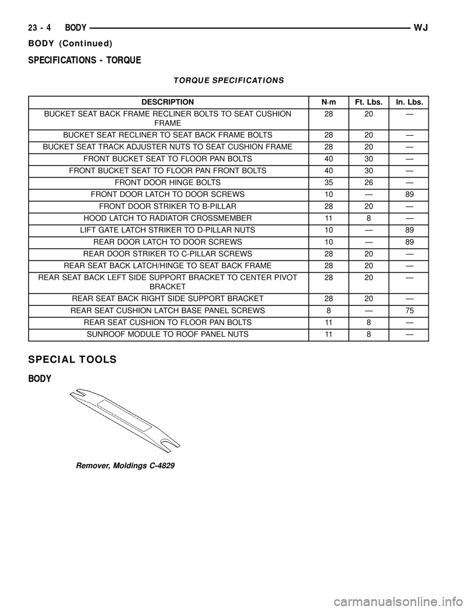
SPECIFICATIONS - TORQUE
TORQUE SPECIFICATIONS
DESCRIPTION N´m Ft. Lbs. In. Lbs.
BUCKET SEAT BACK FRAME RECLINER BOLTS TO SEAT CUSHION
FRAME28 20 Ð
BUCKET SEAT RECLINER TO SEAT BACK FRAME BOLTS 28 20 Ð
BUCKET SEAT TRACK ADJUSTER NUTS TO SEAT CUSHION FRAME 28 20 Ð
FRONT BUCKET SEAT TO FLOOR PAN BOLTS 40 30 Ð
FRONT BUCKET SEAT TO FLOOR PAN FRONT BOLTS 40 30 Ð
FRONT DOOR HINGE BOLTS 35 26 Ð
FRONT DOOR LATCH TO DOOR SCREWS 10 Ð 89
FRONT DOOR STRIKER TO B-PILLAR 28 20 Ð
HOOD LATCH TO RADIATOR CROSSMEMBER 11 8 Ð
LIFT GATE LATCH STRIKER TO D-PILLAR NUTS 10 Ð 89
REAR DOOR LATCH TO DOOR SCREWS 10 Ð 89
REAR DOOR STRIKER TO C-PILLAR SCREWS 28 20 Ð
REAR SEAT BACK LATCH/HINGE TO SEAT BACK FRAME 28 20 Ð
REAR SEAT BACK LEFT SIDE SUPPORT BRACKET TO CENTER PIVOT
BRACKET28 20 Ð
REAR SEAT BACK RIGHT SIDE SUPPORT BRACKET 28 20 Ð
REAR SEAT CUSHION LATCH BASE PANEL SCREWS 8 Ð 75
REAR SEAT CUSHION TO FLOOR PAN BOLTS 11 8 Ð
SUNROOF MODULE TO ROOF PANEL NUTS 11 8 Ð
SPECIAL TOOLS
BODY
Remover, Moldings C-4829
23 - 4 BODYWJ
BODY (Continued)