2003 JEEP GRAND CHEROKEE Tools
[x] Cancel search: ToolsPage 1387 of 2199
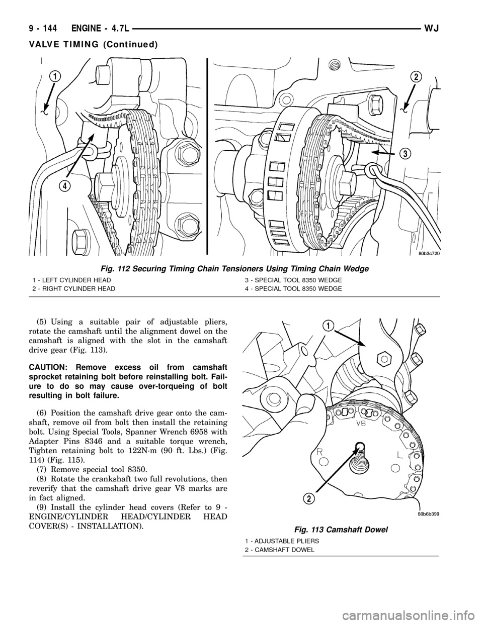
(5) Using a suitable pair of adjustable pliers,
rotate the camshaft until the alignment dowel on the
camshaft is aligned with the slot in the camshaft
drive gear (Fig. 113).
CAUTION: Remove excess oil from camshaft
sprocket retaining bolt before reinstalling bolt. Fail-
ure to do so may cause over-torqueing of bolt
resulting in bolt failure.
(6) Position the camshaft drive gear onto the cam-
shaft, remove oil from bolt then install the retaining
bolt. Using Special Tools, Spanner Wrench 6958 with
Adapter Pins 8346 and a suitable torque wrench,
Tighten retaining bolt to 122N´m (90 ft. Lbs.) (Fig.
114) (Fig. 115).
(7) Remove special tool 8350.
(8) Rotate the crankshaft two full revolutions, then
reverify that the camshaft drive gear V8 marks are
in fact aligned.
(9) Install the cylinder head covers (Refer to 9 -
ENGINE/CYLINDER HEAD/CYLINDER HEAD
COVER(S) - INSTALLATION).
Fig. 112 Securing Timing Chain Tensioners Using Timing Chain Wedge
1 - LEFT CYLINDER HEAD
2 - RIGHT CYLINDER HEAD3 - SPECIAL TOOL 8350 WEDGE
4 - SPECIAL TOOL 8350 WEDGE
Fig. 113 Camshaft Dowel
1 - ADJUSTABLE PLIERS
2 - CAMSHAFT DOWEL
9 - 144 ENGINE - 4.7LWJ
VALVE TIMING (Continued)
Page 1420 of 2199
FUEL SYSTEM
TABLE OF CONTENTS
page page
FUEL DELIVERY..........................1FUEL INJECTION........................31
FUEL DELIVERY
TABLE OF CONTENTS
page page
FUEL DELIVERY
DESCRIPTION..........................2
OPERATION............................2
DIAGNOSIS AND TESTING
FUEL PRESSURE LEAK DOWN TEST......2
STANDARD PROCEDURE - FUEL SYSTEM
PRESSURE RELEASE...................4
SPECIFICATIONS
FUEL SYSTEM PRESSURE..............4
TORQUE - FUEL DELIVERY..............4
SPECIAL TOOLS
FUEL SYSTEM........................5
FUEL FILTER/PRESSURE REGULATOR
DESCRIPTION..........................5
OPERATION............................5
REMOVAL.............................6
INSTALLATION..........................6
FUEL LEVEL SENDING UNIT / SENSOR
DESCRIPTION..........................7
OPERATION............................7
DIAGNOSIS AND TESTING - FUEL LEVEL
SENDING UNIT........................7
REMOVAL.............................7
INSTALLATION..........................8
FUEL LINES
DESCRIPTION..........................8
FUEL PUMP
DESCRIPTION..........................8
OPERATION............................9
DIAGNOSIS AND TESTING
DIAGNOSIS AND TESTING - FUEL PUMP
CAPACITY TEST.......................9
DIAGNOSIS AND TESTING - FUEL PUMP
AMPERAGE TEST......................9FUEL PUMP PRESSURE TEST...........11
FUEL PUMP MODULE
DESCRIPTION.........................13
OPERATION...........................13
REMOVAL.............................13
INSTALLATION.........................14
FUEL RAIL
DESCRIPTION
DESCRIPTION - 4.7L...................15
DESCRIPTION - 4.0L...................15
OPERATION
OPERATION - 4.7L....................15
OPERATION - 4.0L....................15
REMOVAL
REMOVAL - 4.7L......................15
REMOVAL - 4.0L......................17
INSTALLATION
INSTALLATION - 4.7L..................18
INSTALLATION - 4.0L..................18
FUEL TANK
DESCRIPTION.........................19
OPERATION...........................19
REMOVAL.............................19
INSTALLATION.........................20
INLET FILTER
REMOVAL.............................27
INSTALLATION.........................27
QUICK CONNECT FITTING
DESCRIPTION.........................27
STANDARD PROCEDURE - QUICK-CONNECT
FITTINGS...........................27
WJFUEL SYSTEM 14 - 1
Page 1421 of 2199
FUEL DELIVERY
DESCRIPTION
The fuel delivery system consists of:
²the fuel pump module containing the electric
fuel pump, fuel gauge sending unit (fuel level sensor)
and a separate fuel filter located at bottom of pump
module
²a separate combination fuel filter/fuel pressure
regulator
²fuel tubes/lines/hoses
²quick-connect fittings
²fuel injector rail
²fuel injectors
²fuel tank
²fuel tank filler/vent tube assembly
²fuel tank filler tube cap
²accelerator pedal
²throttle cable
OPERATION
The fuel tank assembly consists of: the fuel tank,
fuel tank shield, fuel tank straps, fuel pump module
assembly, fuel pump module locknut/gasket, and fuel
tank check valve (refer to Emission Control System
for fuel tank check valve information).
A fuel filler/vent tube assembly using a pressure/
vacuum, 1/4 turn fuel filler cap is used. The fuel
filler tube contains a flap door located below the fuel
fill cap.
Also to be considered part of the fuel system is the
evaporation control system. This is designed to
reduce the emission of fuel vapors into the atmo-
sphere. The description and function of the Evapora-
tive Control System is found in Emission Control
Systems.
Both fuel filters (at bottom of fuel pump module
and within fuel pressure regulator) are designed for
extended service. They do not require normal sched-
uled maintenance. Filters should only be replaced if
a diagnostic procedure indicates to do so.
DIAGNOSIS AND TESTING
FUEL PRESSURE LEAK DOWN TEST
Use this test in conjunction with the Fuel Pump
Pressure Test and Fuel Pump Capacity Test.
Check Valve Operation:The electric fuel pump
outlet contains a one-way check valve to prevent fuel
flow back into the tank and to maintain fuel supply
line pressure (engine warm) when pump is not oper-
ational. It is also used to keep the fuel supply line
full of gasoline when pump is not operational. After
the vehicle has cooled down, fuel pressure may drop
to 0 psi (cold fluid contracts), but liquid gasoline willremain in fuel supply line between the check valve
and fuel injectors.Fuel pressure that has
dropped to 0 psi on a cooled down vehicle
(engine off) is a normal condition.When the elec-
tric fuel pump is activated, fuel pressure should
immediately(1±2 seconds) rise to specification.
Abnormally long periods of cranking to restart a
hotengine that has been shut down for a short
period of time may be caused by:
²Fuel pressure bleeding past a fuel injector(s).
²Fuel pressure bleeding past the check valve in
the fuel pump module.
²A defective fuel filter/pressure regulator.
Two #6539, 5/16º, Fuel Line Pressure Test Adapter
Hose Tools are required for the following tests.
(1) Release fuel system pressure. Refer to Fuel
Pressure Release Procedure.
(2) Raise vehicle.
Fuel Line Identification:The fuel filter/pressure
regulator is located in front of the fuel tank and
above the rear axle. It is transversely mounted to a
chassis crossmember (left-to-right). The filter/regula-
tor is equipped with 3 fuel line fittings (2 at one end
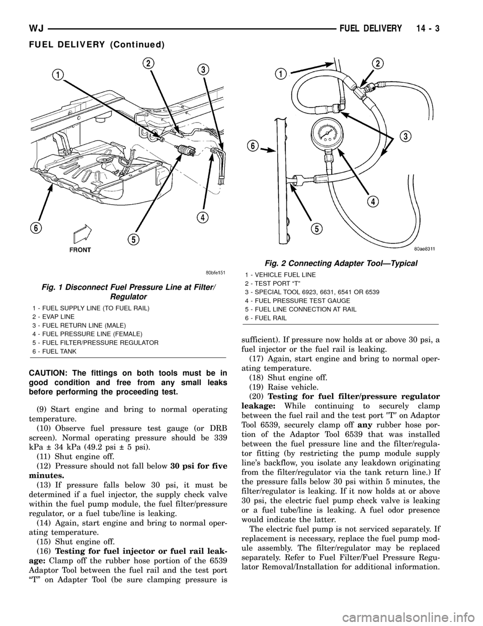
and 1 at the other end). The single fitting facing the
left side of the vehicle is the supply line to the fuel
rail (Fig. 1) . The 2 fittings facing the right side of
the vehicle are connected to the fuel tank. Of these 2
fittings, the fitting towards thefrontis used for fuel
return to the fuel tank. The fitting towards therear
is a pressure line. Thisrearfitting must be discon-
nected for the following step.
(3) See previous step. Disconnect fuel pressure line
atrearof filter/regulator. This is a 5/169quick-con-
nect fitting (Fig. 1) . Refer to Quick-Connect Fittings
for procedures.
(4) Obtain correct Fuel Line Pressure Test Adapter
Hose Tool # 6539 for 5/16º fuel lines. Connect one
end of this Special Tool into the disconnected fuel
pressure line. Connect the other end of the Tool into
fitting on filter/regulator.
(5) Lower vehicle.
(6) Disconnect the fuel inlet line at fuel rail. Refer
to Quick-Connect Fittings for procedures. On some
engines, air cleaner housing removal may be neces-
sary before fuel line disconnection.
(7) Obtain a second Fuel Line Pressure Test
Adapter Hose Tool # 6539 for 5/16º fuel lines. Con-
nect this tool between disconnected fuel line and fuel
rail (Fig. 2) .
(8) Connect the 0-414 kPa (0-60 psi) fuel pressure
test gauge (from Gauge Set 5069) to the test port on
the appropriate Adaptor Tool.NOTE: The DRB III
Scan Tool along with the PEP module, the 500
psi pressure transducer, and the transducer-to-
test port adapter may also be used in place of
the fuel pressure gauge.
14 - 2 FUEL DELIVERYWJ
Page 1422 of 2199
CAUTION: The fittings on both tools must be in
good condition and free from any small leaks
before performing the proceeding test.
(9) Start engine and bring to normal operating
temperature.
(10) Observe fuel pressure test gauge (or DRB
screen). Normal operating pressure should be 339
kPa 34 kPa (49.2 psi 5 psi).
(11) Shut engine off.
(12) Pressure should not fall below30 psi for five
minutes.
(13) If pressure falls below 30 psi, it must be
determined if a fuel injector, the supply check valve
within the fuel pump module, the fuel filter/pressure
regulator, or a fuel tube/line is leaking.
(14) Again, start engine and bring to normal oper-
ating temperature.
(15) Shut engine off.
(16)Testing for fuel injector or fuel rail leak-
age:Clamp off the rubber hose portion of the 6539
Adaptor Tool between the fuel rail and the test port
ªTº on Adapter Tool (be sure clamping pressure issufficient). If pressure now holds at or above 30 psi, a
fuel injector or the fuel rail is leaking.
(17) Again, start engine and bring to normal oper-
ating temperature.
(18) Shut engine off.
(19) Raise vehicle.
(20)Testing for fuel filter/pressure regulator
leakage:While continuing to securely clamp
between the fuel rail and the test port9T9on Adaptor
Tool 6539, securely clamp offanyrubber hose por-
tion of the Adaptor Tool 6539 that was installed
between the fuel pressure line and the filter/regula-
tor fitting (by restricting the pump module supply
line's backflow, you isolate any leakdown originating
from the filter/regulator via the tank return line.) If
the pressure falls below 30 psi within 5 minutes, the
filter/regulator is leaking. If it now holds at or above
30 psi, the electric fuel pump check valve is leaking
or a fuel tube/line is leaking. A fuel odor presence
would indicate the latter.
The electric fuel pump is not serviced separately. If
replacement is necessary, replace the fuel pump mod-
ule assembly. The filter/regulator may be replaced
separately. Refer to Fuel Filter/Fuel Pressure Regu-
lator Removal/Installation for additional information.
Fig. 1 Disconnect Fuel Pressure Line at Filter/
Regulator
1 - FUEL SUPPLY LINE (TO FUEL RAIL)
2 - EVAP LINE
3 - FUEL RETURN LINE (MALE)
4 - FUEL PRESSURE LINE (FEMALE)
5 - FUEL FILTER/PRESSURE REGULATOR
6 - FUEL TANK
Fig. 2 Connecting Adapter ToolÐTypical
1 - VEHICLE FUEL LINE
2 - TEST PORT ªTº
3 - SPECIAL TOOL 6923, 6631, 6541 OR 6539
4 - FUEL PRESSURE TEST GAUGE
5 - FUEL LINE CONNECTION AT RAIL
6 - FUEL RAIL
WJFUEL DELIVERY 14 - 3
FUEL DELIVERY (Continued)
Page 1424 of 2199
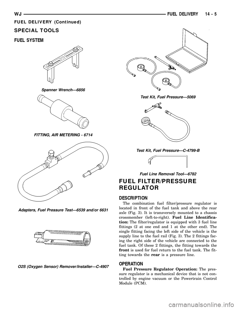
SPECIAL TOOLS
FUEL SYSTEM
FUEL FILTER/PRESSURE
REGULATOR
DESCRIPTION
The combination fuel filter/pressure regulator is
located in front of the fuel tank and above the rear
axle (Fig. 3). It is transversely mounted to a chassis
crossmember (left-to-right).Fuel Line Identifica-
tion:The filter/regulator is equipped with 3 fuel line
fittings (2 at one end and 1 at the other end). The
single fitting facing the left side of the vehicle is the
supply line to the fuel rail (Fig. 3). The 2 fittings fac-
ing the right side of the vehicle are connected to the
fuel tank. Of these 2 fittings, the fitting towards the
frontis used for fuel return to the fuel tank. The fit-
ting towards therearis a pressure line.
OPERATION
Fuel Pressure Regulator Operation:The pres-
sure regulator is a mechanical device that is not con-
trolled by engine vacuum or the Powertrain Control
Module (PCM).
Spanner WrenchÐ6856
FITTING, AIR METERING - 6714
Adapters, Fuel Pressure TestÐ6539 and/or 6631
O2S (Oxygen Sensor) Remover/InstallerÐC-4907
Test Kit, Fuel PressureÐ5069
Test Kit, Fuel PressureÐC-4799-B
Fuel Line Removal ToolÐ6782
WJFUEL DELIVERY 14 - 5
FUEL DELIVERY (Continued)
Page 1446 of 2199
INLET FILTER
REMOVAL
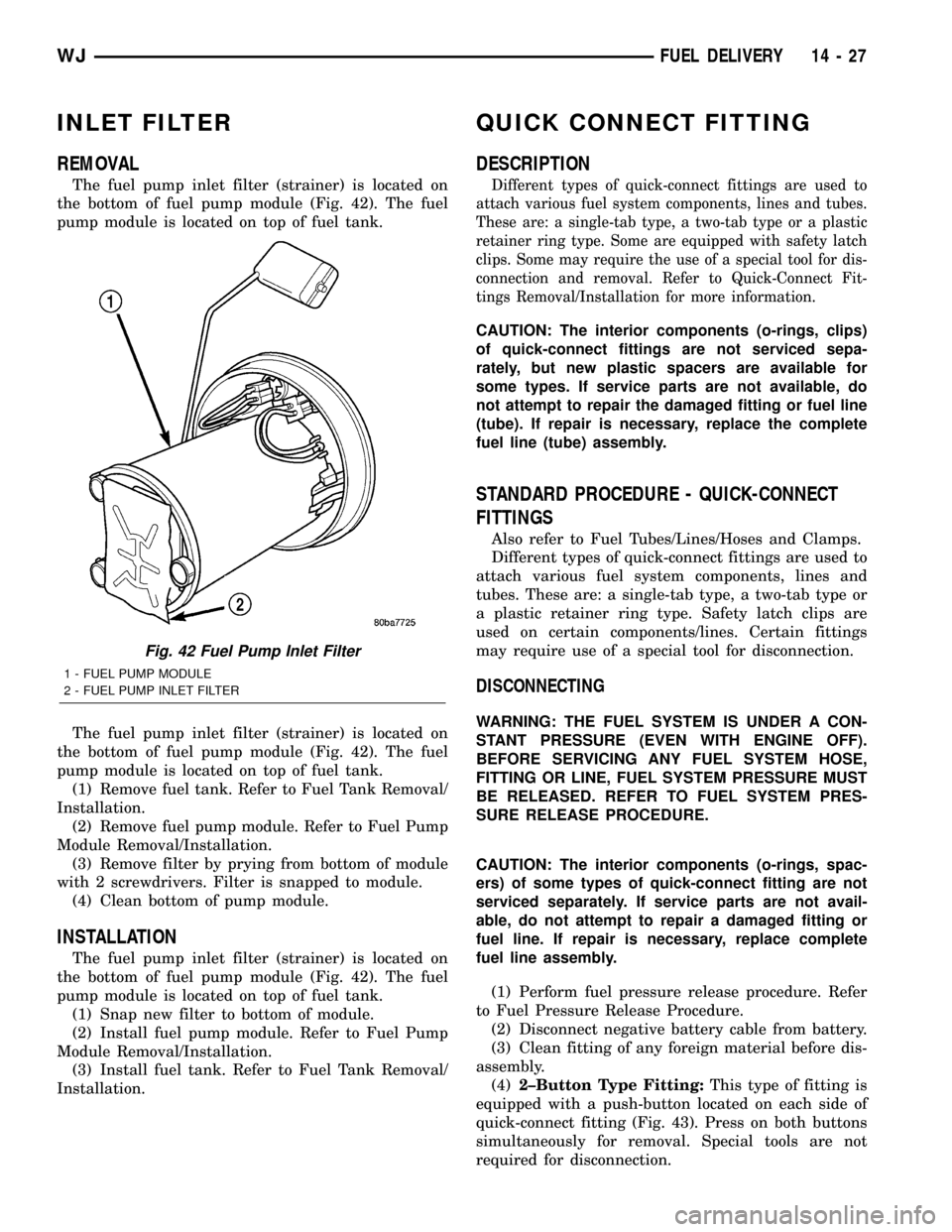
The fuel pump inlet filter (strainer) is located on
the bottom of fuel pump module (Fig. 42). The fuel
pump module is located on top of fuel tank.
The fuel pump inlet filter (strainer) is located on
the bottom of fuel pump module (Fig. 42). The fuel
pump module is located on top of fuel tank.
(1) Remove fuel tank. Refer to Fuel Tank Removal/
Installation.
(2) Remove fuel pump module. Refer to Fuel Pump
Module Removal/Installation.
(3) Remove filter by prying from bottom of module
with 2 screwdrivers. Filter is snapped to module.
(4) Clean bottom of pump module.
INSTALLATION
The fuel pump inlet filter (strainer) is located on
the bottom of fuel pump module (Fig. 42). The fuel
pump module is located on top of fuel tank.
(1) Snap new filter to bottom of module.
(2) Install fuel pump module. Refer to Fuel Pump
Module Removal/Installation.
(3) Install fuel tank. Refer to Fuel Tank Removal/
Installation.
QUICK CONNECT FITTING
DESCRIPTION
Different types of quick-connect fittings are used to
attach various fuel system components, lines and tubes.
These are: a single-tab type, a two-tab type or a plastic
retainer ring type. Some are equipped with safety latch
clips. Some may require the use of a special tool for dis-
connection and removal. Refer to Quick-Connect Fit-
tings Removal/Installation for more information.
CAUTION: The interior components (o-rings, clips)
of quick-connect fittings are not serviced sepa-
rately, but new plastic spacers are available for
some types. If service parts are not available, do
not attempt to repair the damaged fitting or fuel line
(tube). If repair is necessary, replace the complete
fuel line (tube) assembly.
STANDARD PROCEDURE - QUICK-CONNECT
FITTINGS
Also refer to Fuel Tubes/Lines/Hoses and Clamps.
Different types of quick-connect fittings are used to
attach various fuel system components, lines and
tubes. These are: a single-tab type, a two-tab type or
a plastic retainer ring type. Safety latch clips are
used on certain components/lines. Certain fittings
may require use of a special tool for disconnection.
DISCONNECTING
WARNING: THE FUEL SYSTEM IS UNDER A CON-
STANT PRESSURE (EVEN WITH ENGINE OFF).
BEFORE SERVICING ANY FUEL SYSTEM HOSE,
FITTING OR LINE, FUEL SYSTEM PRESSURE MUST
BE RELEASED. REFER TO FUEL SYSTEM PRES-
SURE RELEASE PROCEDURE.
CAUTION: The interior components (o-rings, spac-
ers) of some types of quick-connect fitting are not
serviced separately. If service parts are not avail-
able, do not attempt to repair a damaged fitting or
fuel line. If repair is necessary, replace complete
fuel line assembly.
(1) Perform fuel pressure release procedure. Refer
to Fuel Pressure Release Procedure.
(2) Disconnect negative battery cable from battery.
(3) Clean fitting of any foreign material before dis-
assembly.
(4)2±Button Type Fitting:This type of fitting is
equipped with a push-button located on each side of
quick-connect fitting (Fig. 43). Press on both buttons
simultaneously for removal. Special tools are not
required for disconnection.
Fig. 42 Fuel Pump Inlet Filter
1 - FUEL PUMP MODULE
2 - FUEL PUMP INLET FILTER
WJFUEL DELIVERY 14 - 27
Page 1447 of 2199
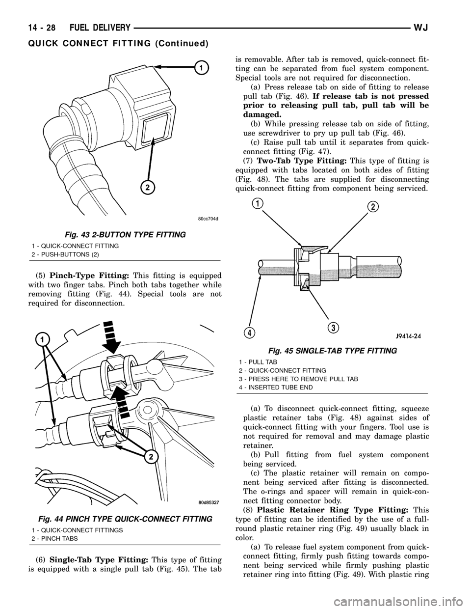
(5)Pinch-Type Fitting:This fitting is equipped
with two finger tabs. Pinch both tabs together while
removing fitting (Fig. 44). Special tools are not
required for disconnection.
(6)Single-Tab Type Fitting:This type of fitting
is equipped with a single pull tab (Fig. 45). The tabis removable. After tab is removed, quick-connect fit-
ting can be separated from fuel system component.
Special tools are not required for disconnection.
(a) Press release tab on side of fitting to release
pull tab (Fig. 46).If release tab is not pressed
prior to releasing pull tab, pull tab will be
damaged.
(b) While pressing release tab on side of fitting,
use screwdriver to pry up pull tab (Fig. 46).
(c) Raise pull tab until it separates from quick-
connect fitting (Fig. 47).
(7)Two-Tab Type Fitting:This type of fitting is
equipped with tabs located on both sides of fitting
(Fig. 48). The tabs are supplied for disconnecting
quick-connect fitting from component being serviced.
(a) To disconnect quick-connect fitting, squeeze
plastic retainer tabs (Fig. 48) against sides of
quick-connect fitting with your fingers. Tool use is
not required for removal and may damage plastic
retainer.
(b) Pull fitting from fuel system component
being serviced.
(c) The plastic retainer will remain on compo-
nent being serviced after fitting is disconnected.
The o-rings and spacer will remain in quick-con-
nect fitting connector body.
(8)Plastic Retainer Ring Type Fitting:This
type of fitting can be identified by the use of a full-
round plastic retainer ring (Fig. 49) usually black in
color.
(a) To release fuel system component from quick-
connect fitting, firmly push fitting towards compo-
nent being serviced while firmly pushing plastic
retainer ring into fitting (Fig. 49). With plastic ring
Fig. 43 2-BUTTON TYPE FITTING
1 - QUICK-CONNECT FITTING
2 - PUSH-BUTTONS (2)
Fig. 44 PINCH TYPE QUICK-CONNECT FITTING
1 - QUICK-CONNECT FITTINGS
2 - PINCH TABS
Fig. 45 SINGLE-TAB TYPE FITTING
1 - PULL TAB
2 - QUICK-CONNECT FITTING
3 - PRESS HERE TO REMOVE PULL TAB
4 - INSERTED TUBE END
14 - 28 FUEL DELIVERYWJ
QUICK CONNECT FITTING (Continued)
Page 1484 of 2199
COLUMN
TABLE OF CONTENTS
page page
COLUMN
DESCRIPTION
SERVICE WARNINGS AND CAUTIONS......7
REMOVAL.............................8
INSTALLATION.........................11
SPECIFICATIONS
TORQUE CHART......................12
SPECIAL TOOLS
STEERING COLUMN...................12
IGNITION SWITCH
DESCRIPTION.........................12
DIAGNOSIS AND TESTING - IGNITION
SWITCH............................12
REMOVAL
IGNITION SWITCH REMOVAL............13INSTALLATION
IGNITION SWITCH INSTALLATION........13
KEY-IN IGNITION SWITCH
DESCRIPTION.........................14
OPERATION...........................14
DIAGNOSIS AND TESTING
KEY-IN IGNITION SWITCH..............14
LOCK CYLINDER
REMOVAL.............................14
INSTALLATION.........................15
STEERING WHEEL
REMOVAL.............................15
INSTALLATION.........................15
COLUMN
DESCRIPTION
SERVICE WARNINGS AND CAUTIONS
DESCRIPTION
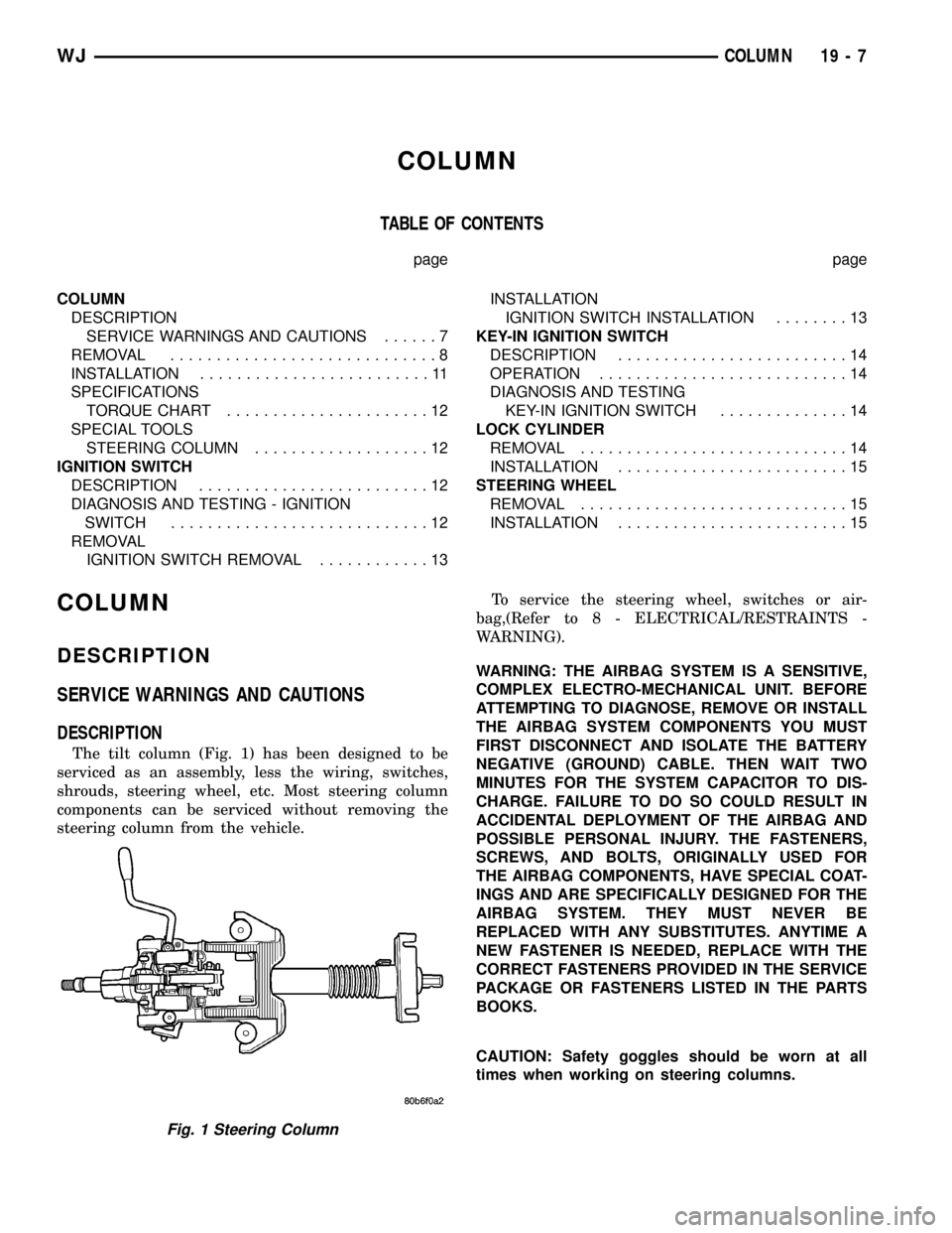
The tilt column (Fig. 1) has been designed to be
serviced as an assembly, less the wiring, switches,
shrouds, steering wheel, etc. Most steering column
components can be serviced without removing the
steering column from the vehicle.To service the steering wheel, switches or air-
bag,(Refer to 8 - ELECTRICAL/RESTRAINTS -
WARNING).
WARNING: THE AIRBAG SYSTEM IS A SENSITIVE,
COMPLEX ELECTRO-MECHANICAL UNIT. BEFORE
ATTEMPTING TO DIAGNOSE, REMOVE OR INSTALL
THE AIRBAG SYSTEM COMPONENTS YOU MUST
FIRST DISCONNECT AND ISOLATE THE BATTERY
NEGATIVE (GROUND) CABLE. THEN WAIT TWO
MINUTES FOR THE SYSTEM CAPACITOR TO DIS-
CHARGE. FAILURE TO DO SO COULD RESULT IN
ACCIDENTAL DEPLOYMENT OF THE AIRBAG AND
POSSIBLE PERSONAL INJURY. THE FASTENERS,
SCREWS, AND BOLTS, ORIGINALLY USED FOR
THE AIRBAG COMPONENTS, HAVE SPECIAL COAT-
INGS AND ARE SPECIFICALLY DESIGNED FOR THE
AIRBAG SYSTEM. THEY MUST NEVER BE
REPLACED WITH ANY SUBSTITUTES. ANYTIME A
NEW FASTENER IS NEEDED, REPLACE WITH THE
CORRECT FASTENERS PROVIDED IN THE SERVICE
PACKAGE OR FASTENERS LISTED IN THE PARTS
BOOKS.
CAUTION: Safety goggles should be worn at all
times when working on steering columns.
Fig. 1 Steering Column
WJCOLUMN 19 - 7