2003 JEEP GRAND CHEROKEE Ads
[x] Cancel search: AdsPage 1467 of 2199

MAP SENSOR
DESCRIPTION
DESCRIPTION
On the 4.0L six-cylinder engine the MAP sensor is
mounted to the engine throttle body. On the 4.7L V-8
engine the MAP sensor is mounted to front of the
intake manifold.
DESCRIPTION - 4.7L
The MAP sensor is located on the front of the
intake manifold. An o-ring seals the sensor to the
intake manifold.
OPERATION
The MAP sensor is used as an input to the Power-
train Control Module (PCM). It contains a silicon
based sensing unit to provide data on the manifold
vacuum that draws the air/fuel mixture into the com-
bustion chamber. The PCM requires this information
to determine injector pulse width and spark advance.
When manifold absolute pressure (MAP) equals
Barometric pressure, the pulse width will be at max-
imum.
A 5 volt reference is supplied from the PCM and
returns a voltage signal to the PCM that reflects
manifold pressure. The zero pressure reading is 0.5V
and full scale is 4.5V. For a pressure swing of 0±15
psi, the voltage changes 4.0V. To operate the sensor,
it is supplied a regulated 4.8 to 5.1 volts. Ground is
provided through the low-noise, sensor return circuit
at the PCM.
The MAP sensor input is the number one contrib-
utor to fuel injector pulse width. The most important
function of the MAP sensor is to determine baromet-
ric pressure. The PCM needs to know if the vehicle is
at sea level or at a higher altitude, because the air
density changes with altitude. It will also help to cor-
rect for varying barometric pressure. Barometric
pressure and altitude have a direct inverse correla-
tion; as altitude goes up, barometric goes down. At
key-on, the PCM powers up and looks at MAP volt-
age, and based upon the voltage it sees, it knows the
current barometric pressure (relative to altitude).
Once the engine starts, the PCM looks at the voltage
again, continuously every 12 milliseconds, and com-
pares the current voltage to what it was at key-on.
The difference between current voltage and what it
was at key-on, is manifold vacuum.
During key-on (engine not running) the sensor
reads (updates) barometric pressure. A normal range
can be obtained by monitoring a known good sensor.
As the altitude increases, the air becomes thinner
(less oxygen). If a vehicle is started and driven to avery different altitude than where it was at key-on,
the barometric pressure needs to be updated. Any
time the PCM sees Wide Open Throttle (WOT), based
upon Throttle Position Sensor (TPS) angle and RPM,
it will update barometric pressure in the MAP mem-
ory cell. With periodic updates, the PCM can make
its calculations more effectively.
The PCM uses the MAP sensor input to aid in cal-
culating the following:
²Manifold pressure
²Barometric pressure
²Engine load
²Injector pulse-width
²Spark-advance programs
²Shift-point strategies (certain automatic trans-
missions only)
²Idle speed
²Decel fuel shutoff
The MAP sensor signal is provided from a single
piezoresistive element located in the center of a dia-
phragm. The element and diaphragm are both made
of silicone. As manifold pressure changes, the dia-
phragm moves causing the element to deflect, which
stresses the silicone. When silicone is exposed to
stress, its resistance changes. As manifold vacuum
increases, the MAP sensor input voltage decreases
proportionally. The sensor also contains electronics
that condition the signal and provide temperature
compensation.
The PCM recognizes a decrease in manifold pres-
sure by monitoring a decrease in voltage from the
reading stored in the barometric pressure memory
cell. The MAP sensor is a linear sensor; meaning as
pressure changes, voltage changes proportionately.
The range of voltage output from the sensor is usu-
ally between 4.6 volts at sea level to as low as 0.3
volts at 26 in. of Hg. Barometric pressure is the pres-
sure exerted by the atmosphere upon an object. At
sea level on a standard day, no storm, barometric
pressure is approximately 29.92 in Hg. For every 100
feet of altitude, barometric pressure drops .10 in. Hg.
If a storm goes through it can change barometric
pressure from what should be present for that alti-
tude. You should know what the average pressure
and corresponding barometric pressure is for your
area.
REMOVAL
REMOVAL - 4.0L
The MAP sensor is mounted to the side of the
throttle body (Fig. 40). An L-shaped rubber fitting is
used to connect the MAP sensor to throttle body (Fig.
31).
(1) Remove air cleaner duct and air resonator box
at throttle body.
14 - 48 FUEL INJECTIONWJ
Page 1470 of 2199

In Closed Loop operation, the PCM monitors cer-
tain O2 sensor input(s) along with other inputs, and
adjusts the injector pulse width accordingly. During
Open Loop operation, the PCM ignores the O2 sensor
input. The PCM adjusts injector pulse width based
on preprogrammed (fixed) values and inputs from
other sensors.
Upstream Sensor (Non-California Emissions):
The upstream sensor (1/1) provides an input voltage
to the PCM. The input tells the PCM the oxygen con-
tent of the exhaust gas. The PCM uses this informa-
tion to fine tune fuel delivery to maintain the correct
oxygen content at the downstream oxygen sensor.
The PCM will change the air/fuel ratio until the
upstream sensor inputs a voltage that the PCM has
determined will make the downstream sensor output
(oxygen content) correct.
The upstream oxygen sensor also provides an input
to determine catalytic convertor efficiency.
Downstream Sensor (Non-California Emis-
sions):The downstream oxygen sensor (1/2) is also
used to determine the correct air-fuel ratio. As the
oxygen content changes at the downstream sensor,
the PCM calculates how much air-fuel ratio change is
required. The PCM then looks at the upstream oxy-
gen sensor voltage and changes fuel delivery until
the upstream sensor voltage changes enough to cor-
rect the downstream sensor voltage (oxygen content).
The downstream oxygen sensor also provides an
input to determine catalytic convertor efficiency.
Upstream Sensors (California Engines):Tw o
upstream sensors are used (1/1 and 2/1). The 1/1 sen-
sor is the first sensor to receive exhaust gases from
the #1 cylinder. They provide an input voltage to the
PCM. The input tells the PCM the oxygen content of
the exhaust gas. The PCM uses this information to
fine tune fuel delivery to maintain the correct oxygen
content at the downstream oxygen sensors. The PCM
will change the air/fuel ratio until the upstream sen-
sors input a voltage that the PCM has determined
will make the downstream sensors output (oxygen
content) correct.
The upstream oxygen sensors also provide an input
to determine mini-catalyst efficiency. Main catalytic
convertor efficiency is not calculated with this pack-
age.
Downstream Sensors (California Engines):
Two downstream sensors are used (1/2 and 2/2). The
downstream sensors are used to determine the cor-
rect air-fuel ratio. As the oxygen content changes at
the downstream sensor, the PCM calculates how
much air-fuel ratio change is required. The PCM
then looks at the upstream oxygen sensor voltage,
and changes fuel delivery until the upstream sensor
voltage changes enough to correct the downstream
sensor voltage (oxygen content).The downstream oxygen sensors also provide an
input to determine mini-catalyst efficiency. Main cat-
alytic convertor efficiency is not calculated with this
package.
Engines equipped with either a downstream sen-
sor(s), or a post-catalytic sensor, will monitor cata-
lytic convertor efficiency. If efficiency is below
emission standards, the Malfunction Indicator Lamp
(MIL) will be illuminated and a Diagnostic Trouble
Code (DTC) will be set. Refer to Monitored Systems
in Emission Control Systems for additional informa-
tion.
REMOVAL
Never apply any type of grease to the oxygen
sensor electrical connector, or attempt any sol-
dering of the sensor wiring harness.
Oxygen sensor (O2S) locations are shown in (Fig.
33) and (Fig. 34).
WARNING: THE EXHAUST MANIFOLD, EXHAUST
PIPES AND CATALYTIC CONVERTER(S) BECOME
VERY HOT DURING ENGINE OPERATION. ALLOW
ENGINE TO COOL BEFORE REMOVING OXYGEN
SENSOR.
(1) Raise and support vehicle.
(2) Disconnect O2S pigtail harness from main wir-
ing harness.
(3) If equipped, disconnect sensor wire harness
mounting clips from engine or body.
CAUTION: When disconnecting sensor electrical
connector, do not pull directly on wire going into
sensor.
(4) Remove O2S sensor with an oxygen sensor
removal and installation tool.
INSTALLATION
Threads of new oxygen sensors are factory coated
with anti-seize compound to aid in removal.DO
NOT add any additional anti-seize compound to
threads of a new oxygen sensor.
(1) Install O2S sensor. Tighten to 30 N´m (22 ft.
lbs.) torque.
(2) Connect O2S sensor wire connector to main
wiring harness.
(3) If equipped, connect sensor wire harness
mounting clips to engine or body.When Equipped:
The O2S pigtail harness must be clipped and/or
bolted back to their original positions on
engine or body to prevent mechanical damage
to wiring..
(4) Lower vehicle.
WJFUEL INJECTION 14 - 51
O2S SENSOR (Continued)
Page 1480 of 2199

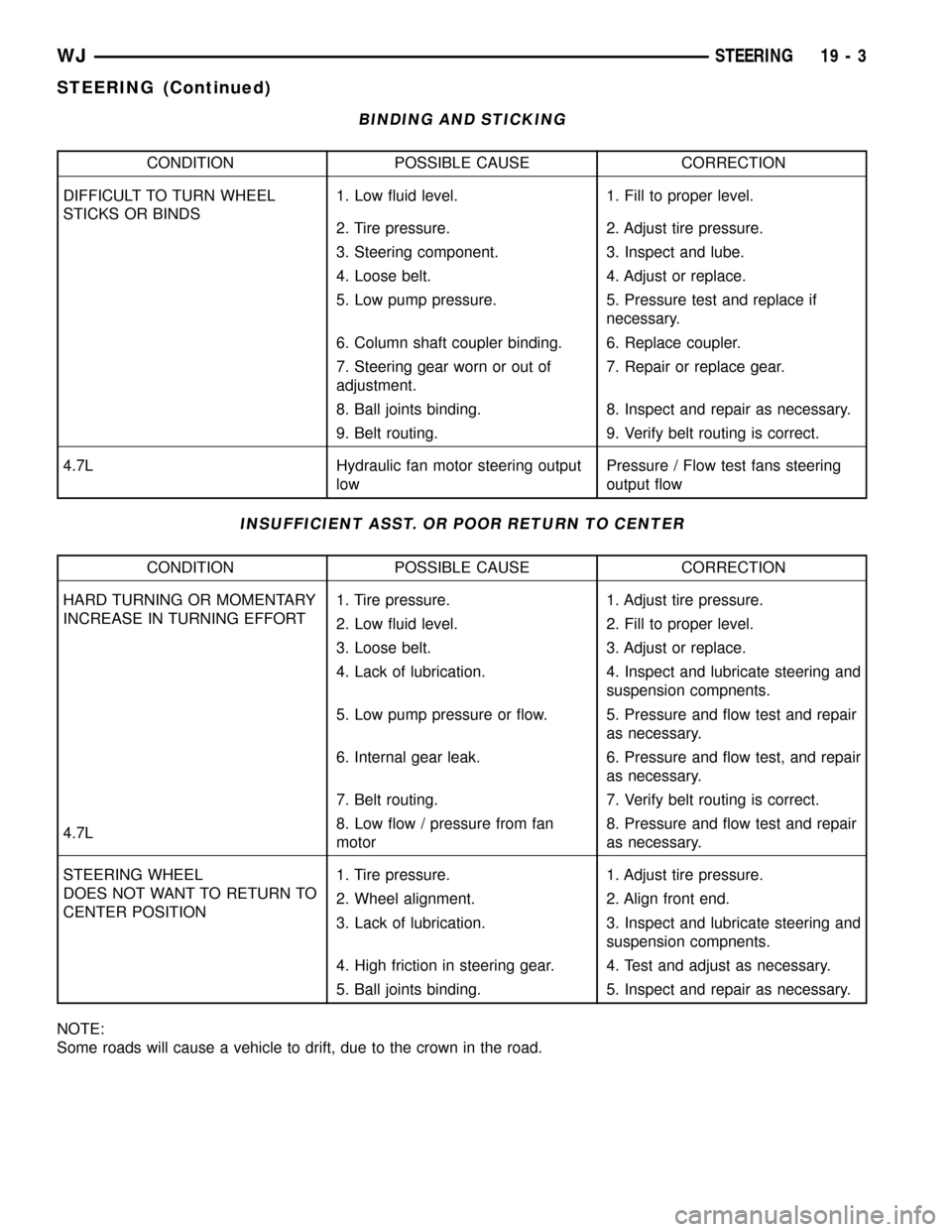
BINDING AND STICKING
CONDITION POSSIBLE CAUSE CORRECTION
DIFFICULT TO TURN WHEEL
STICKS OR BINDS1. Low fluid level. 1. Fill to proper level.
2. Tire pressure. 2. Adjust tire pressure.
3. Steering component. 3. Inspect and lube.
4. Loose belt. 4. Adjust or replace.
5. Low pump pressure. 5. Pressure test and replace if
necessary.
6. Column shaft coupler binding. 6. Replace coupler.
7. Steering gear worn or out of
adjustment.7. Repair or replace gear.
8. Ball joints binding. 8. Inspect and repair as necessary.
9. Belt routing. 9. Verify belt routing is correct.
4.7L Hydraulic fan motor steering output
lowPressure / Flow test fans steering
output flow
INSUFFICIENT ASST. OR POOR RETURN TO CENTER
CONDITION POSSIBLE CAUSE CORRECTION
HARD TURNING OR MOMENTARY
INCREASE IN TURNING EFFORT1. Tire pressure. 1. Adjust tire pressure.
2. Low fluid level. 2. Fill to proper level.
3. Loose belt. 3. Adjust or replace.
4. Lack of lubrication. 4. Inspect and lubricate steering and
suspension compnents.
5. Low pump pressure or flow. 5. Pressure and flow test and repair
as necessary.
6. Internal gear leak. 6. Pressure and flow test, and repair
as necessary.
7. Belt routing. 7. Verify belt routing is correct.
4.7L8. Low flow / pressure from fan
motor8. Pressure and flow test and repair
as necessary.
STEERING WHEEL
DOES NOT WANT TO RETURN TO
CENTER POSITION1. Tire pressure. 1. Adjust tire pressure.
2. Wheel alignment. 2. Align front end.
3. Lack of lubrication. 3. Inspect and lubricate steering and
suspension compnents.
4. High friction in steering gear. 4. Test and adjust as necessary.
5. Ball joints binding. 5. Inspect and repair as necessary.
NOTE:
Some roads will cause a vehicle to drift, due to the crown in the road.
WJSTEERING 19 - 3
STEERING (Continued)
Page 1481 of 2199

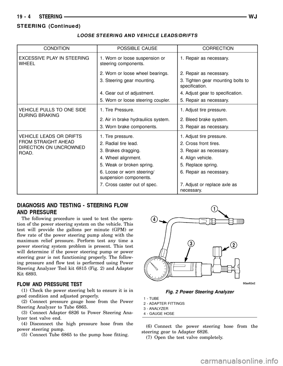
LOOSE STEERING AND VEHICLE LEADS/DRIFTS
CONDITION POSSIBLE CAUSE CORRECTION
EXCESSIVE PLAY IN STEERING
WHEEL1. Worn or loose suspension or
steering components.1. Repair as necessary.
2. Worn or loose wheel bearings. 2. Repair as necessary.
3. Steering gear mounting. 3. Tighten gear mounting bolts to
specification.
4. Gear out of adjustment. 4. Adjust gear to specification.
5. Worn or loose steering coupler. 5. Repair as necessary.
VEHICLE PULLS TO ONE SIDE
DURING BRAKING1. Tire Pressure. 1. Adjust tire pressure.
2. Air in brake hydrauliics system. 2. Bleed brake system.
3. Worn brake components. 3. Repair as necessary.
VEHICLE LEADS OR DRIFTS
FROM STRAIGHT AHEAD
DIRECTION ON UNCROWNED
ROAD.1. Tire pressure. 1. Adjust tire pressure.
2. Radial tire lead. 2. Cross front tires.
3. Brakes dragging. 3. Repair as necessary.
4. Wheel alignment. 4. Align vehicle.
5. Weak or broken spring. 5. Replace spring.
6. Loose or worn steering/
suspension components.6. Repair as necessary.
7. Cross caster out of spec. 7. Adjust or replace axle as
necessary.
DIAGNOSIS AND TESTING - STEERING FLOW
AND PRESSURE
The following procedure is used to test the opera-
tion of the power steering system on the vehicle. This
test will provide the gallons per minute (GPM) or
flow rate of the power steering pump along with the
maximum relief pressure. Perform test any time a
power steering system problem is present. This test
will determine if the power steering pump or power
steering gear is not functioning properly. The follow-
ing pressure and flow test is performed using Power
Steering Analyzer Tool kit 6815 (Fig. 2) and Adapter
Kit 6893.
FLOW AND PRESSURE TEST
(1) Check the power steering belt to ensure it is in
good condition and adjusted properly.
(2) Connect pressure gauge hose from the Power
Steering Analyzer to Tube 6865.
(3) Connect Adapter 6826 to Power Steering Ana-
lyzer test valve end.
(4) Disconnect the high pressure hose from the
power steering pump.
(5) Connect Tube 6865 to the pump hose fitting.(6) Connect the power steering hose from the
steering gear to Adapter 6826.
(7) Open the test valve completely.Fig. 2 Power Steering Analyzer
1 - TUBE
2 - ADAPTER FITTINGS
3 - ANALYZER
4 - GAUGE HOSE
19 - 4 STEERINGWJ
STEERING (Continued)
Page 1535 of 2199

leaks are generally deposited on the housing and not
on the converter.
TORQUE CONVERTER LEAK POINTS
Possible sources of converter leaks are:
(1) Leaks at the weld joint around the outside
diameter weld (Fig. 12).
(2) Leaks at the converter hub weld (Fig. 12).
CONVERTER HOUSING AREA LEAK CORRECTION
(1) Remove converter.
(2) Tighten front band adjusting screw until band
is tight around front clutch retainer. This prevents
front/rear clutches from coming out when oil pump is
removed.
(3) Remove oil pump and remove pump seal.
Inspect pump housing drainback and vent holes for
obstructions. Clear holes with solvent and wire.
(4) Inspect pump bushing and converter hub. If
bushing is scored, replace it. If converter hub is
scored, either polish it with crocus cloth or replace
converter.(5) Install new pump seal, O-ring, and gasket.
Replace oil pump if cracked, porous or damaged in
any way. Be sure to loosen the front band before
installing the oil pump, damage to the oil pump seal
may occur if the band is still tightened to the front
clutch retainer.
(6) Loosen kickdown lever pin access plug three
turns. Apply LoctiteŸ 592, or PermatextNo.2to
plug threads and tighten plug to 17 N´m (150 in. lbs.)
torque.
(7) Adjust front band.
(8) Lubricate pump seal and converter hub with
transmission fluid or petroleum jelly and install con-
verter.
(9) Install transmission and converter housing
dust shield.
(10) Lower vehicle.
DIAGNOSIS AND TESTING - DIAGNOSIS
CHARTS
The diagnosis charts provide additional reference
when diagnosing a transmission fault. The charts
provide general information on a variety of transmis-
sion, overdrive unit and converter clutch fault condi-
tions.
The hydraulic flow charts in the Schematics and
Diagrams section of this group, outline fluid flow and
hydraulic circuitry. Circuit operation is provided for
PARK, NEUTRAL, FIRST, SECOND, THIRD,
FOURTH, MANUAL FIRST, MANUAL SECOND,
and REVERSE gear ranges. Normal working pres-
sures are also supplied for each of the gear ranges.
Fig. 11 Converter Housing Leak Paths
1 - PUMP SEAL
2 - PUMP VENT
3 - PUMP BOLT
4 - PUMP GASKET
5 - CONVERTER HOUSING
6 - CONVERTER
7 - REAR MAIN SEAL LEAK
Fig. 12 Converter Leak Points - Typical
1 - OUTSIDE DIAMETER WELD
2 - TORQUE CONVERTER HUB WELD
3 - STARTER RING GEAR
4 - LUG
21 - 16 AUTOMATIC TRANSMISSION - 42REWJ
AUTOMATIC TRANSMISSION - 42RE (Continued)
Page 1536 of 2199

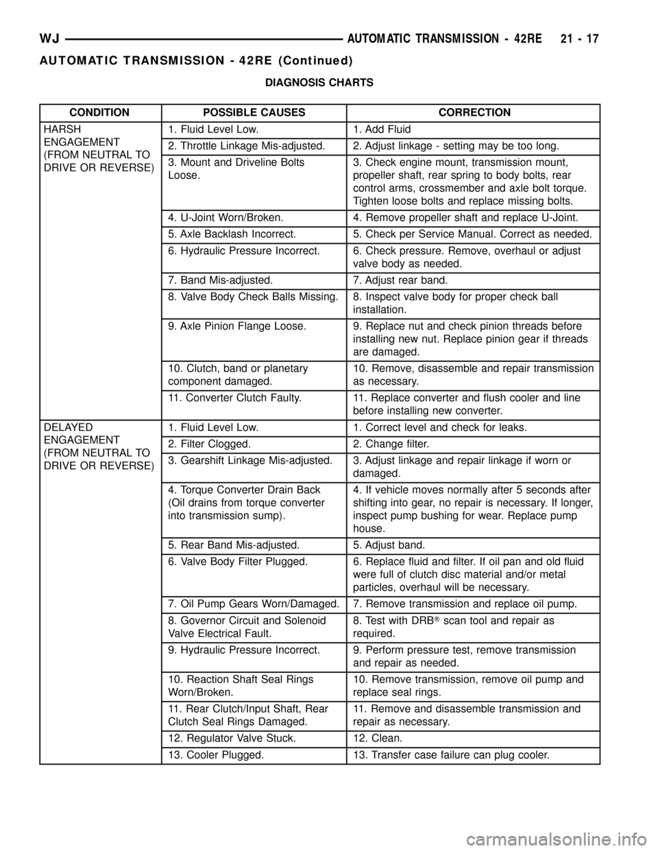
DIAGNOSIS CHARTS
CONDITION POSSIBLE CAUSES CORRECTION
HARSH
ENGAGEMENT
(FROM NEUTRAL TO
DRIVE OR REVERSE)1. Fluid Level Low. 1. Add Fluid
2. Throttle Linkage Mis-adjusted. 2. Adjust linkage - setting may be too long.
3. Mount and Driveline Bolts
Loose.3. Check engine mount, transmission mount,
propeller shaft, rear spring to body bolts, rear
control arms, crossmember and axle bolt torque.
Tighten loose bolts and replace missing bolts.
4. U-Joint Worn/Broken. 4. Remove propeller shaft and replace U-Joint.
5. Axle Backlash Incorrect. 5. Check per Service Manual. Correct as needed.
6. Hydraulic Pressure Incorrect. 6. Check pressure. Remove, overhaul or adjust
valve body as needed.
7. Band Mis-adjusted. 7. Adjust rear band.
8. Valve Body Check Balls Missing. 8. Inspect valve body for proper check ball
installation.
9. Axle Pinion Flange Loose. 9. Replace nut and check pinion threads before
installing new nut. Replace pinion gear if threads
are damaged.
10. Clutch, band or planetary
component damaged.10. Remove, disassemble and repair transmission
as necessary.
11. Converter Clutch Faulty. 11. Replace converter and flush cooler and line
before installing new converter.
DELAYED
ENGAGEMENT
(FROM NEUTRAL TO
DRIVE OR REVERSE)1. Fluid Level Low. 1. Correct level and check for leaks.
2. Filter Clogged. 2. Change filter.
3. Gearshift Linkage Mis-adjusted. 3. Adjust linkage and repair linkage if worn or
damaged.
4. Torque Converter Drain Back
(Oil drains from torque converter
into transmission sump).4. If vehicle moves normally after 5 seconds after
shifting into gear, no repair is necessary. If longer,
inspect pump bushing for wear. Replace pump
house.
5. Rear Band Mis-adjusted. 5. Adjust band.
6. Valve Body Filter Plugged. 6. Replace fluid and filter. If oil pan and old fluid
were full of clutch disc material and/or metal
particles, overhaul will be necessary.
7. Oil Pump Gears Worn/Damaged. 7. Remove transmission and replace oil pump.
8. Governor Circuit and Solenoid
Valve Electrical Fault.8. Test with DRBTscan tool and repair as
required.
9. Hydraulic Pressure Incorrect. 9. Perform pressure test, remove transmission
and repair as needed.
10. Reaction Shaft Seal Rings
Worn/Broken.10. Remove transmission, remove oil pump and
replace seal rings.
11. Rear Clutch/Input Shaft, Rear
Clutch Seal Rings Damaged.11. Remove and disassemble transmission and
repair as necessary.
12. Regulator Valve Stuck. 12. Clean.
13. Cooler Plugged. 13. Transfer case failure can plug cooler.
WJAUTOMATIC TRANSMISSION - 42RE 21 - 17
AUTOMATIC TRANSMISSION - 42RE (Continued)
Page 1545 of 2199

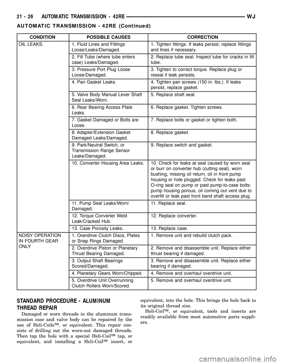
CONDITION POSSIBLE CAUSES CORRECTION
OIL LEAKS. 1. Fluid Lines and Fittings
Loose/Leaks/Damaged.1. Tighten fittings. If leaks persist, replace fittings
and lines if necessary.
2. Fill Tube (where tube enters
case) Leaks/Damaged.2. Replace tube seal. Inspect tube for cracks in fill
tube.
3. Pressure Port Plug Loose
Loose/Damaged.3. Tighten to correct torque. Replace plug or
reseal if leak persists.
4. Pan Gasket Leaks. 4. Tighten pan screws (150 in. lbs.). If leaks
persist, replace gasket.
5. Valve Body Manual Lever Shaft
Seal Leaks/Worn.5. Replace shaft seal.
6. Rear Bearing Access Plate
Leaks.6. Replace gasket. Tighten screws.
7. Gasket Damaged or Bolts are
Loose.7. Replace bolts or gasket or tighten both.
8. Adapter/Extension Gasket
Damaged Leaks/Damaged.8. Replace gasket.
9. Park/Neutral Switch, or
Transmission Range Sensor
Leaks/Damaged.9. Replace switch and gasket.
10. Converter Housing Area Leaks. 10. Check for leaks at seal caused by worn seal
or burr on converter hub (cutting seal), worn
bushing, missing oil return, oil in front pump
housing or hole plugged. Check for leaks past
O-ring seal on pump or past pump-to-case bolts;
pump housing porous, oil coming out vent due to
overfill or leak past front band shaft access plug.
11. Pump Seal Leaks/Worn/
Damaged.11. Replace seal.
12. Torque Converter Weld
Leak/Cracked Hub.12. Replace converter.
13. Case Porosity Leaks. 13. Replace case.
NOISY OPERATION
IN FOURTH GEAR
ONLY1. Overdrive Clutch Discs, Plates
or Snap Rings Damaged.1. Remove unit and rebuild clutch pack.
2. Overdrive Piston or Planetary
Thrust Bearing Damaged.2. Remove and disassemble unit. Replace either
thrust bearing if damaged.
3. Output Shaft Bearings
Scored/Damaged.3. Remove and disassemble unit. Replace either
bearing if damaged.
4. Planetary Gears Worn/Chipped. 4. Remove and overhaul overdrive unit.
5. Overdrive Unit Overrunning
Clutch Rollers Worn/Scored.5. Remove and overhaul overdrive unit.
STANDARD PROCEDURE - ALUMINUM
THREAD REPAIR
Damaged or worn threads in the aluminum trans-
mission case and valve body can be repaired by the
use of Heli-CoilsŸ, or equivalent. This repair con-
sists of drilling out the worn-out damaged threads.
Then tap the hole with a special Heli-CoilŸ tap, or
equivalent, and installing a Heli-CoilŸ insert, orequivalent, into the hole. This brings the hole back to
its original thread size.
Heli-CoilŸ, or equivalent, tools and inserts are
readily available from most automotive parts suppli-
ers.
21 - 26 AUTOMATIC TRANSMISSION - 42REWJ
AUTOMATIC TRANSMISSION - 42RE (Continued)
Page 1553 of 2199

(36) Compress rear servo spring retainer about
1/16 inch with Valve Spring Compressor C-3422-B
(Fig. 38).
(37) Remove rear servo spring retainer snap-ring.
Then remove compressor tools and remove rear servo
spring and piston.
(38) Inspect transmission components.
NOTE: To Service the overrunning clutch cam or
overdrive piston retainer, refer to the Overrunning
Clutch Cam service procedure in this section.
CLEANING
Clean the case in a solvent tank. Flush the case
bores and fluid passages thoroughly with solvent.
Dry the case and all fluid passages with compressed
air. Be sure all solvent is removed from the case and
that all fluid passages are clear.
NOTE: Do not use shop towels or rags to dry the
case (or any other transmission component) unless
they are made from lint-free materials. Lint will stick
to case surfaces and transmission components and
circulate throughout the transmission after assem-
bly. A sufficient quantity of lint can block fluid pas-
sages and interfere with valve body operation.Lubricate transmission parts with MopartATF +4,
type 9602, transmission fluid during overhaul and
assembly. Use petroleum jelly, MopartDoor Ease, or
Ru-GlydeŸ to prelubricate seals, O-rings, and thrust
washers. Petroleum jelly can also be used to hold
parts in place during reassembly.
INSPECTION
Inspect the case for cracks, porous spots, worn
bores, or damaged threads. Damaged threads can be
repaired with Helicoil thread inserts. However, the
case will have to be replaced if it exhibits any type of
damage or wear.
Lubricate the front band adjusting screw threads
with petroleum jelly and thread the screw part-way
into the case. Be sure the screw turns freely.
Inspect the transmission bushings during overhaul.
Bushing condition is important as worn, scored bush-
ings contribute to low pressures, clutch slip and
accelerated wear of other components. However, do
not replace bushings as a matter of course. Replace
bushings only when they are actually worn, or
scored.
Use recommended tools to replace bushings. The
tools are sized and designed to remove, install, and
seat bushings correctly. The bushing replacement
tools are included in Bushing Tool Set C-3887-B.
Pre-sized service bushings are available for
replacement purposes. Only the sun gear bushings
are not serviced.
The use of crocus cloth is permissible where neces-
sary, providing it is used carefully. When used on
shafts, or valves, use extreme care to avoid rounding
off sharp edges. Sharp edges are vital as they pre-
vent foreign matter from getting between the valve
and valve bore.
Do not reuse oil seals, gaskets, seal rings, or
O-rings during overhaul. Replace these parts as a
matter of course. Also do not reuse snap rings or
E-clips that are bent or distorted. Replace these parts
as well.
ASSEMBLY
Do not allow dirt, grease, or foreign material to
enter the case or transmission components during
assembly. Keep the transmission case and compo-
nents clean. Also make sure the tools and workbench
area used for assembly operations are equally clean.
Shop towels used for wiping off tools and hands
must be made fromlint freematerial. Lint will stick
to transmission parts and could interfere with valve
operation, or even restrict fluid passages.
Lubricate the transmission components with
Moparttransmission fluid during reassembly. Use
MopartDoor Ease, or Ru-GlydeŸ on seals and
O-rings to ease installation.
Fig. 38 Compressing Rear Servo Spring
1 - FRONT SERVO SNAP-RING
2 - REAR SERVO SNAP-RING
3 - SPECIAL TOOL
21 - 34 AUTOMATIC TRANSMISSION - 42REWJ
AUTOMATIC TRANSMISSION - 42RE (Continued)