2003 JEEP GRAND CHEROKEE Ads
[x] Cancel search: AdsPage 1395 of 2199

(13) Remove Special Tool 8515, then attach both
sprockets to camshafts. Remove excess oil from bolts,
then Install sprocket bolts, but do not tighten at this
time.
(14) Verify that all plated links are aligned with
the marks on all sprockets and the ªV8º marks on
camshaft sprockets are at the 12 o'clock position (Fig.
127).
CAUTION: Ensure the plate between the left sec-
ondary chain tensioner and block is correctly
installed.
(15) Install both secondary chain tensioners.
Tighten bolts to 28 N´m (250 in. lbs.).
NOTE: Left and right secondary chain tensioners
are not common.
(16) Before installing idler sprocket bolt, lubricate
washer with oil, and tighten idler sprocket assembly
retaining bolt to 34 N´m (25 ft. lbs.).
(17) Remove all locking pins (3) from tensioners.
CAUTION: After pulling locking pins out of each
tensioner, DO NOT manually extend the tensioner(s)
ratchet. Doing so will over tension the chains,
resulting in noise and/or high timing chain loads.
(18) Using Special Tool 6958, Spanner with Adap-
tor Pins 8346, tighten left (Fig. 131) and right (Fig.
132). camshaft sprocket bolts to 122 N´m (90 ft. lbs.).
(19) Rotate engine two full revolutions. Verify tim-
ing marks are at the follow locations:
²primary chain idler sprocket dot is at 12 o'clock
(Fig. 127)
²primary chain crankshaft sprocket dot is at 6
o'clock (Fig. 127)
²secondary chain camshaft sprockets ªV8º marks
are at 12 o'clock (Fig. 127)(20) Lubricate all three chains with engine oil.
(21) After installing all chains, it is recommended
that the idler gear end play be checked (Fig. 133).
The end play must be within 0.10±0.25 mm (0.004±
0.010 in.). If not within specification, the idler gear
must be replaced.
Fig. 131 Tightening Left Side Camshaft Sprocket
Bolt
1 - TORQUE WRENCH
2 - CAMSHAFT SPROCKET
3 - LEFT CYLINDER HEAD
4 - SPECIAL TOOL 6958 SPANNER WITH ADAPTER PINS 8346
9 - 152 ENGINE - 4.7LWJ
TIMING BELT/CHAIN AND SPROCKETS (Continued)
Page 1398 of 2199

EXHAUST SYSTEM
TABLE OF CONTENTS
page page
EXHAUST SYSTEM
DESCRIPTION - EXHAUST SYSTEM.........1
DIAGNOSIS AND TESTING - EXHAUST
SYSTEM.............................3
SPECIFICATIONS
TORQUE.............................3
CATALYTIC CONVERTER - 4.0L
DESCRIPTION - CATALYTIC CONVERTER
4.0L ENGINE..........................4
REMOVAL.............................4
INSPECTION...........................5
INSTALLATION..........................5
CATALYTIC CONVERTER - 4.7L
DESCRIPTION - CATALYTIC CONVERTER.....6
REMOVAL.............................6
INSPECTION...........................7
INSTALLATION..........................7EXHAUST PIPE - 4.0L
REMOVAL.............................8
INSPECTION...........................8
INSTALLATION..........................8
EXHAUST PIPE - 4.7L
REMOVAL.............................10
INSPECTION..........................10
INSTALLATION.........................10
HEAT SHIELDS
DESCRIPTION.........................12
MUFFLER
DESCRIPTION.........................12
REMOVAL.............................12
INSTALLATION.........................12
TAILPIPE
DESCRIPTION.........................13
OPERATION...........................13
EXHAUST SYSTEM
DESCRIPTION - EXHAUST SYSTEM
WARNING: THE NORMAL OPERATING TEMPERA-
TURE OF THE EXHAUST SYSTEM IS VERY HIGH.
THEREFORE, NEVER WORK AROUND OR ATTEMPT
TO SERVICE ANY PART OF THE EXHAUST SYSTEM
UNTIL IT IS COOLED. SPECIAL CARE SHOULD BE
TAKEN WHEN WORKING NEAR THE CATALYTIC
CONVERTER. THE TEMPERATURE OF THE CON-
VERTER RISES TO A HIGH LEVEL AFTER A SHORT
PERIOD OF ENGINE OPERATION TIME.
CAUTION: Avoid application of rust prevention com-
pounds or undercoating materials to exhaust sys-
tem floor pan heat shields. Light overspray near the
edges is permitted. Application of coating will result
in excessive floor pan temperatures and objection-
able fumes.
The exhaust system uses a single muffler with a
welded tailpipe.The 50 State Emissions vehicles use two mini cat-
alytic converters inline with the exhaust pipe below
the exhaust manifolds.
The exhaust manifolds are equipped with ball
flange outlets to assure a tight seal and strain free
connections.
The exhaust system must be properly aligned to
prevent stress, leakage and body contact. If the sys-
tem contacts any body panel, it may amplify objec-
tionable noises originating from the engine or body.
When inspecting an exhaust system, critically
inspect for cracked or loose joints, stripped screw or
bolt threads, corrosion damage and worn, cracked or
broken hangers. Replace all components that are
badly corroded or damaged. DO NOT attempt to
repair.
When replacement is required, use original equip-
ment parts (or their equivalent). This will assure
proper alignment and provide acceptable exhaust
noise levels.
The basic exhaust system consists of exhaust man-
ifold(s), exhaust pipe with oxygen sensors, catalytic
converter(s), heat shield(s), muffler and tailpipe (Fig.
1) and (Fig. 2).
WJEXHAUST SYSTEM 11 - 1
Page 1428 of 2199

OPERATION
Voltage to operate the electric pump is supplied
through the fuel pump relay.
Fuel is drawn in through a filter at the bottom of
the module and pushed through the electric motor
gearset to the pump outlet.
Check Valve Operation:The pump outlet con-
tains a one-way check valve to prevent fuel flow back
into the tank and to maintain fuel supply line pres-
sure (engine warm) when pump is not operational. It
is also used to keep the fuel supply line full of gaso-
line when pump is not operational. After the vehicle
has cooled down, fuel pressure may drop to 0 psi
(cold fluid contracts), but liquid gasoline will remain
in fuel supply line between the check valve and fuel
injectors.Fuel pressure that has dropped to 0
psi on a cooled down vehicle (engine off) is a
normal condition.Refer to the Fuel Pressure Leak
Down Test for more information.
The electric fuel pump is not a separate, service-
able component.
DIAGNOSIS AND TESTING
DIAGNOSIS AND TESTING - FUEL PUMP
CAPACITY TEST
Before performing this test, verify fuel pump
pressure. Refer to Fuel Pump Pressure Test.
Use this test in conjunction with the Fuel Pres-
sure Leak Down Test.
(1) Release fuel system pressure. Refer to Fuel
Pressure Release Procedure.
(2) Disconnect fuel supply line at fuel rail. Refer to
Quick-Connect Fittings. Some engines may require
air cleaner housing removal before line disconnection.
(3) Obtain correct Fuel Line Pressure Test Adapter
Tool Hose. Tool number 6539 is used for 5/16º fuel
lines and tool number 6631 is used for 3/8º fuel lines.
(4) Connect correct Fuel Line Pressure Test
Adapter Tool Hose into disconnected fuel supply line.
Insert other end of Adaptor Tool Hose into a gradu-
ated container.
(5) Remove fuel fill cap.
(6) To activate fuel pump and pressurize system,
obtain DRBtscan tool and actuate ASD Fuel System
Test.
(7) A good fuel pump will deliver at least 1/4 liter
of fuel in 7 seconds. Do not operate fuel pump for
longer than 7 seconds with fuel line disconnected as
fuel pump module reservoir may run empty.
(a) If capacity is lower than specification, but
fuel pump can be heard operating through fuel fill
cap opening, check for a kinked/damaged fuel sup-
ply line somewhere between fuel rail and fuel
pump module.(b) If line is not kinked/damaged, and fuel pres-
sure is OK, but capacity is low, replace fuel filter/
fuel pressure regulator. The filter/regulator may be
serviced separately on certain applications. Refer
to Fuel Filter/Fuel Pressure Regulator Removal/In-
stallation for additional information.
(c) If both fuel pressure and capacity are low,
replace fuel pump module assembly. Refer to Fuel
Pump Module Removal/Installation.
DIAGNOSIS AND TESTING - FUEL PUMP
AMPERAGE TEST
This amperage (current draw) test is to be done in
conjunction with the Fuel Pump Pressure Test, Fuel
Pump Capacity Test and Fuel Pressure Leak Down
Test. Before performing the amperage test, be sure
the temperature of the fuel tank is above 50É F (10É
C).
The DRBtScan Tool along with the DRB Low Cur-
rent Shunt (LCS) adapter (Fig. 8) and its test leads
will be used to check fuel pump amperage specifica-
tions.
(1) Be sure fuel tank contains fuel before starting
test. If tank is empty or near empty, amperage read-
ings will be incorrect.
(2) Obtain LCS adapter.
(3) Plug cable from LCS adapter into DRB scan
tool at SET 1 receptacle.
(4) Plug DRB into vehicle 16±way connector (data
link connector).
Fig. 8 LOW CURRENT SHUNT
1 - LOW CURRENT SHUNT ADAPTER
2 - PLUG TO DRB
3 - TEST LEAD RECEPTACLES
WJFUEL DELIVERY 14 - 9
FUEL PUMP (Continued)
Page 1429 of 2199

(5) Connect (-) and (+) test cable leads into LCS
adapter receptacles. Use10 amp (10A +)receptacle
and common (-) receptacles.
(6) Gain access to MAIN MENU on DRB screen.
(7) Press DVOM button on DRB.
(8) Using left/right arrow keys, highlight CHAN-
NEL 1 function on DRB screen.
(9) Press ENTER three times.
(10) Using up/down arrow keys, highlight RANGE
on DRB screen (screen will default to 2 amp scale).
(11) Press ENTER to change 2 amp scale to 10
amp scale.This step must be done to prevent
damage to DRB scan tool or LCS adapter
(blown fuse).
(12) Remove cover from Power Distribution Center
(PDC).
(13) Remove fuel pump relay from PDC. Refer to
label on PDC cover for relay location.
WARNING: BEFORE PROCEEDING TO NEXT STEP,
NOTE THE FUEL PUMP WILL BE ACTIVATED AND
SYSTEM PRESSURE WILL BE PRESENT. THIS WILL
OCCUR AFTER CONNECTING TEST LEADS FROM
LCS ADAPTER INTO FUEL PUMP RELAY CAVITIES.
THE FUEL PUMP WILL OPERATE EVEN WITH IGNI-
TION KEY IN OFF POSITION. BEFORE ATTACHING
TEST LEADS, BE SURE ALL FUEL LINES AND
FUEL SYSTEM COMPONENTS ARE CONNECTED.
CAUTION: To prevent possible damage to the vehi-
cle electrical system and LCS adapter, the test
leads must be connected into relay cavities exactly
as shown in following steps.
Depending upon vehicle model, year or engine con-
figuration, three different types of relays may be
used: Type-1, type-2 and type±3.
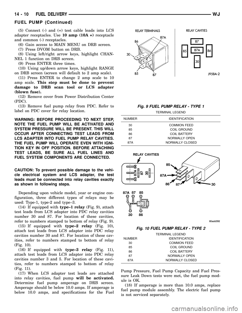
(14) If equipped withtype±1 relay(Fig. 9), attach
test leads from LCS adapter into PDC relay cavities
number 30 and 87. For location of these cavities,
refer to numbers stamped to bottom of relay (Fig. 9).
(15) If equipped withtype±2 relay(Fig. 10),
attach test leads from LCS adapter into PDC relay
cavities number 30 and 87. For location of these cav-
ities, refer to numbers stamped to bottom of relay
(Fig. 10).
(16) If equipped withtype±3 relay(Fig. 11),
attach test leads from LCS adapter into PDC relay
cavities number 3 and 5. For location of these cavi-
ties, refer to numbers stamped to bottom of relay
(Fig. 11).
(17) When LCS adapter test leads are attached
into relay cavities, fuel pumpwill be activated.
Determine fuel pump amperage on DRB screen.
Amperage should be below 10.0 amps. If amperage is
below 10.0 amps, and specifications for the FuelPump Pressure, Fuel Pump Capacity and Fuel Pres-
sure Leak Down tests were met, the fuel pump mod-
ule is OK.
(18) If amperage is more than 10.0 amps, replace
fuel pump module assembly. The electric fuel pump
is not serviced separately.
Fig. 9 FUEL PUMP RELAY - TYPE 1
TERMINAL LEGEND
NUMBER IDENTIFICATION
30 COMMON FEED
85 COIL GROUND
86 COIL BATTERY
87 NORMALLY OPEN
87A NORMALLY CLOSED
Fig. 10 FUEL PUMP RELAY - TYPE 2
TERMINAL LEGEND
NUMBER IDENTIFICATION
30 COMMON FEED
85 COIL GROUND
86 COIL BATTERY
87 NORMALLY OPEN
87A NORMALLY CLOSED
14 - 10 FUEL DELIVERYWJ
FUEL PUMP (Continued)
Page 1430 of 2199

(19) Disconnect test leads from relay cavities
immediately after testing.
FUEL PUMP PRESSURE TEST
Use this test in conjunction with other fuel system
tests. Refer to the Fuel Pump Capacity Test, Fuel
Pressure Leak Down Test and Fuel Pump Amperage
Test.
Check Valve Operation:The electric fuel pump
outlet contains a one-way check valve to prevent fuel
flow back into the tank and to maintain fuel supply
line pressure (engine warm) when pump is not oper-
ational. It is also used to keep the fuel supply line
full of gasoline when pump is not operational. After
the vehicle has cooled down, fuel pressure may drop
to 0 psi (cold fluid contracts), but liquid gasoline will
remain in fuel supply line between the check valve
and fuel injectors.Fuel pressure that has
dropped to 0 psi on a cooled down vehicle
(engine off) is a normal condition.When the elec-
tric fuel pump is activated, fuel pressure should
immediately(1±2 seconds) rise to specification.
The fuel system is equipped with a combination
fuel filter/fuel pressure regulator. The fuel pressure
regulator is not controlled by engine vacuum.
WARNING: THE FUEL SYSTEM IS UNDER CON-
STANT FUEL PRESSURE EVEN WITH THE ENGINE
OFF. BEFORE DISCONNECTING FUEL LINE AT
FUEL RAIL, THIS PRESSURE MUST BE RELEASED.REFER TO THE FUEL SYSTEM PRESSURE
RELEASE PROCEDURE.
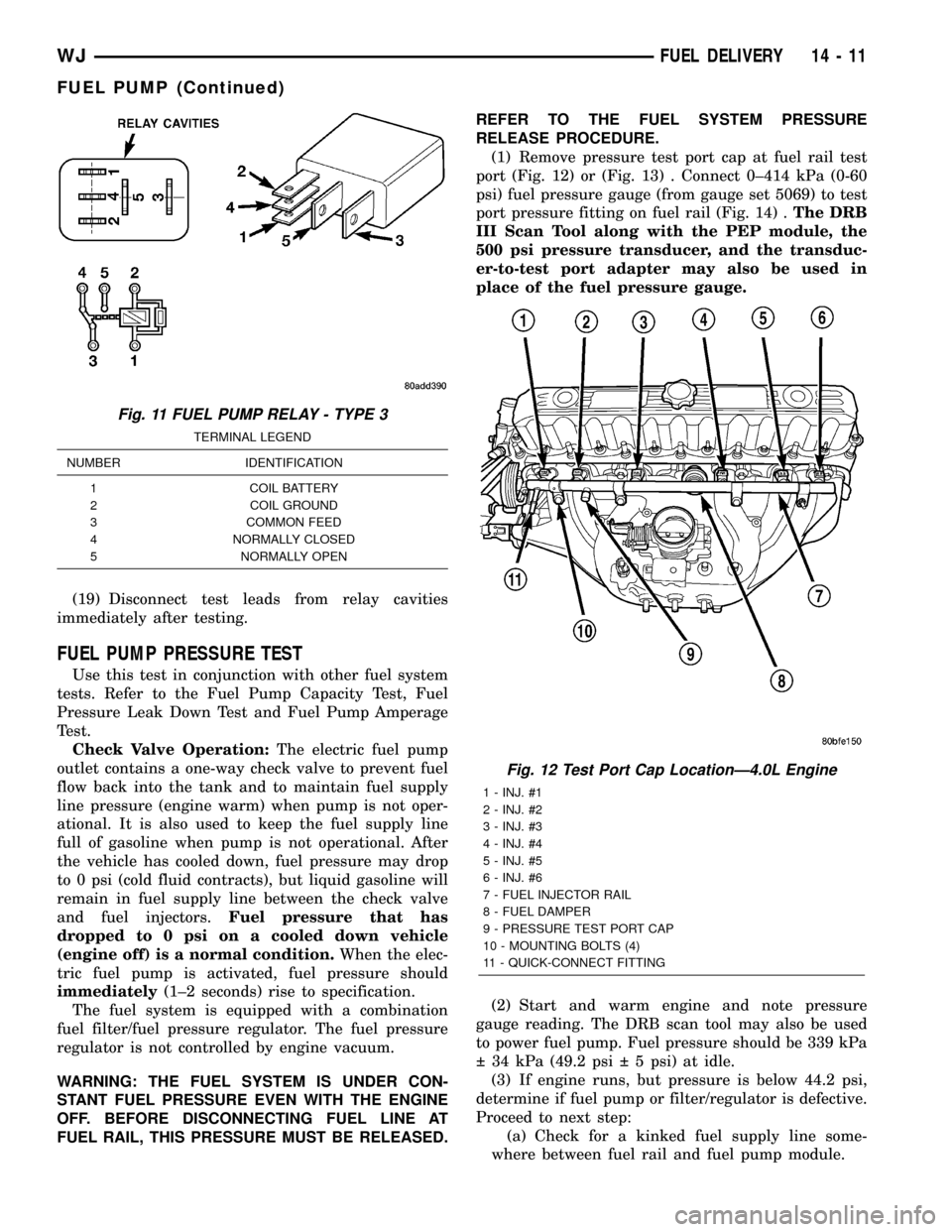
(1) Remove pressure test port cap at fuel rail test
port (Fig. 12) or (Fig. 13) . Connect 0±414 kPa (0-60
psi) fuel pressure gauge (from gauge set 5069) to test
port pressure fitting on fuel rail (Fig. 14) .The DRB
III Scan Tool along with the PEP module, the
500 psi pressure transducer, and the transduc-
er-to-test port adapter may also be used in
place of the fuel pressure gauge.
(2) Start and warm engine and note pressure
gauge reading. The DRB scan tool may also be used
to power fuel pump. Fuel pressure should be 339 kPa
34 kPa (49.2 psi 5 psi) at idle.
(3) If engine runs, but pressure is below 44.2 psi,
determine if fuel pump or filter/regulator is defective.
Proceed to next step:
(a) Check for a kinked fuel supply line some-
where between fuel rail and fuel pump module.
Fig. 11 FUEL PUMP RELAY - TYPE 3
TERMINAL LEGEND
NUMBER IDENTIFICATION
1 COIL BATTERY
2 COIL GROUND
3 COMMON FEED
4 NORMALLY CLOSED
5 NORMALLY OPEN
Fig. 12 Test Port Cap LocationÐ4.0L Engine
1 - INJ. #1
2 - INJ. #2
3 - INJ. #3
4 - INJ. #4
5 - INJ. #5
6 - INJ. #6
7 - FUEL INJECTOR RAIL
8 - FUEL DAMPER
9 - PRESSURE TEST PORT CAP
10 - MOUNTING BOLTS (4)
11 - QUICK-CONNECT FITTING
WJFUEL DELIVERY 14 - 11
FUEL PUMP (Continued)
Page 1433 of 2199

(2) Drain fuel tank and remove tank. Refer to Fuel
Tank Removal/Installation.
(3) Thoroughly wash and clean area around pump
module to prevent contaminants from entering tank.
(4) Disconnect fuel return and pressure lines from
fuel pump module fittings (Fig. 16). Refer to Quick-
Connect Fittings for procedures.
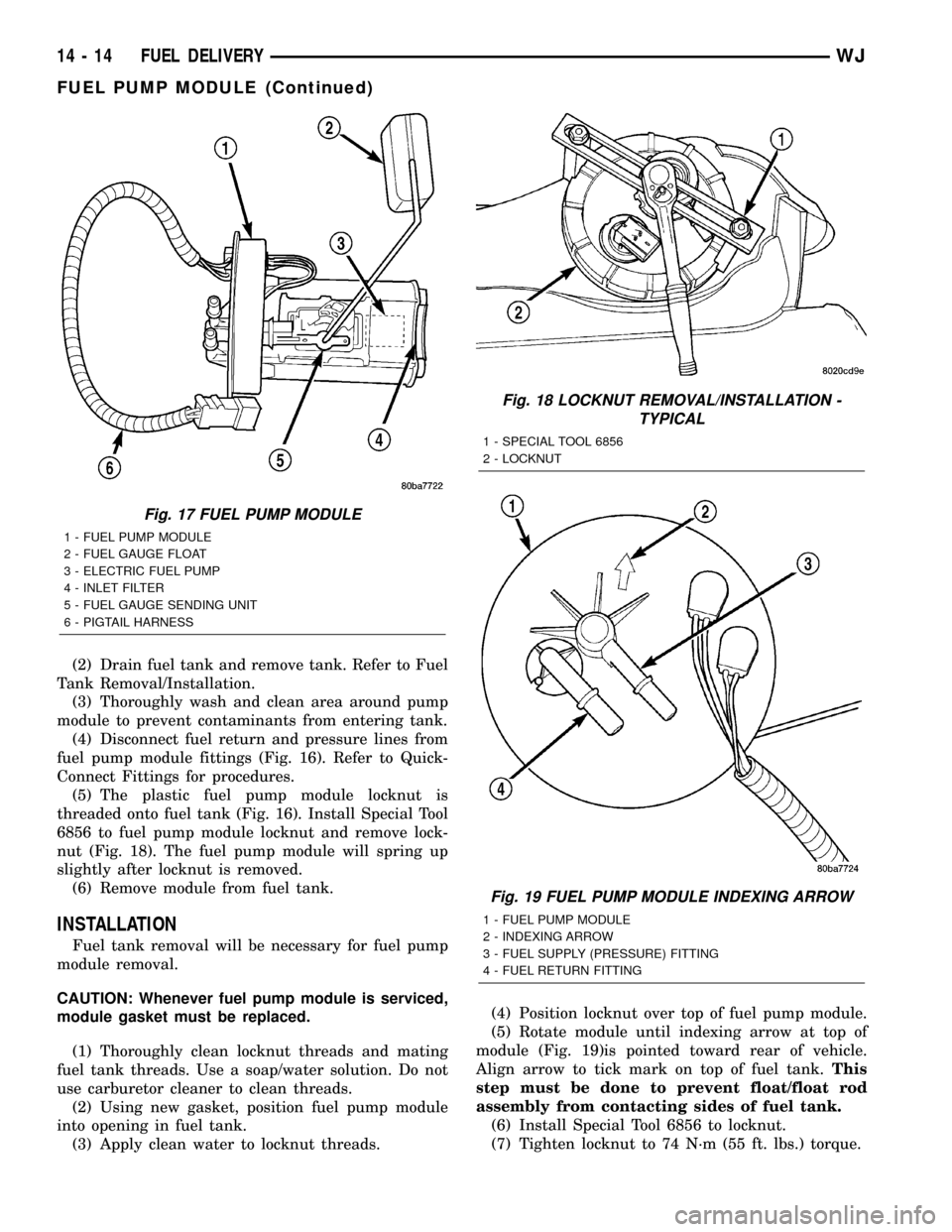
(5) The plastic fuel pump module locknut is
threaded onto fuel tank (Fig. 16). Install Special Tool
6856 to fuel pump module locknut and remove lock-
nut (Fig. 18). The fuel pump module will spring up
slightly after locknut is removed.
(6) Remove module from fuel tank.
INSTALLATION
Fuel tank removal will be necessary for fuel pump
module removal.
CAUTION: Whenever fuel pump module is serviced,
module gasket must be replaced.
(1) Thoroughly clean locknut threads and mating
fuel tank threads. Use a soap/water solution. Do not
use carburetor cleaner to clean threads.
(2) Using new gasket, position fuel pump module
into opening in fuel tank.
(3) Apply clean water to locknut threads.(4) Position locknut over top of fuel pump module.
(5) Rotate module until indexing arrow at top of
module (Fig. 19)is pointed toward rear of vehicle.
Align arrow to tick mark on top of fuel tank.This
step must be done to prevent float/float rod
assembly from contacting sides of fuel tank.
(6) Install Special Tool 6856 to locknut.
(7) Tighten locknut to 74 N´m (55 ft. lbs.) torque.
Fig. 17 FUEL PUMP MODULE
1 - FUEL PUMP MODULE
2 - FUEL GAUGE FLOAT
3 - ELECTRIC FUEL PUMP
4 - INLET FILTER
5 - FUEL GAUGE SENDING UNIT
6 - PIGTAIL HARNESS
Fig. 18 LOCKNUT REMOVAL/INSTALLATION -
TYPICAL
1 - SPECIAL TOOL 6856
2 - LOCKNUT
Fig. 19 FUEL PUMP MODULE INDEXING ARROW
1 - FUEL PUMP MODULE
2 - INDEXING ARROW
3 - FUEL SUPPLY (PRESSURE) FITTING
4 - FUEL RETURN FITTING
14 - 14 FUEL DELIVERYWJ
FUEL PUMP MODULE (Continued)
Page 1463 of 2199

The PCM determines injector on-time (pulse width)
based on various inputs.
DIAGNOSIS AND TESTING - FUEL INJECTOR
To perform a complete test of the fuel injectors and
their circuitry, use the DRB scan tool and refer to the
appropriate Powertrain Diagnostics Procedures man-
ual. To test the injector only, refer to the following:
Disconnect the fuel injector wire harness connector
from the injector. The injector is equipped with 2
electrical terminals (pins). Place an ohmmeter across
the terminals. Resistance reading should be approxi-
mately 12 ohms 1.2 ohms at 20ÉC (68ÉF).
REMOVAL
WARNING: THE FUEL SYSTEM IS UNDER CON-
STANT PRESSURE EVEN WITH ENGINE OFF.
BEFORE SERVICING FUEL INJECTOR(S), FUEL
SYSTEM PRESSURE MUST BE RELEASED.
To remove one or more fuel injectors, the fuel rail
assembly must be removed from engine.
(1) Perform Fuel System Pressure Release Proce-
dure.
(2) Remove fuel injector rail. Refer to Fuel Injector
Rail Removal/Installation.
(3) Remove clip(s) retaining injector(s) to fuel rail
(Fig. 25).
(4) Remove injector(s) from fuel rail.
INSTALLATION
(1) Apply a small amount of engine oil to each fuel
injector o-ring. This will help in fuel rail installation.
(2) Install injector(s) and injector clip(s) to fuel
rail.
(3) Install fuel rail assembly. Refer to Fuel Injector
Rail Removal/Installation.
(4) Start engine and check for leaks.
FUEL PUMP RELAY
DESCRIPTION
The 5±pin, 12±volt, fuel pump relay is located in
the Power Distribution Center (PDC). Refer to the
label on the PDC cover for relay location.
OPERATION
The Powertrain Control Module (PCM) energizes
the electric fuel pump through the fuel pump relay.
The fuel pump relay is energized by first applying
battery voltage to it when the ignition key is turned
ON, and then applying a ground signal to the relay
from the PCM.
Whenever the ignition key is turned ON, the elec-
tric fuel pump will operate. But, the PCM will shut-
down the ground circuit to the fuel pump relay in
approximately 1±3 seconds unless the engine is oper-
ating or the starter motor is engaged.
IDLE AIR CONTROL MOTOR
DESCRIPTION
The IAC stepper motor is mounted to the throttle
body, and regulates the amount of air bypassing the
control of the throttle plate. As engine loads and
ambient temperatures change, engine rpm changes.
A pintle on the IAC stepper motor protrudes into a
passage in the throttle body, controlling air flow
through the passage. The IAC is controlled by the
Powertrain Control Module (PCM) to maintain the
target engine idle speed.
OPERATION
At idle, engine speed can be increased by retract-
ing the IAC motor pintle and allowing more air to
pass through the port, or it can be decreased by
restricting the passage with the pintle and diminish-
ing the amount of air bypassing the throttle plate.
The IAC is called a stepper motor because it is
moved (rotated) in steps, or increments. Opening the
IAC opens an air passage around the throttle blade
which increases RPM.Fig. 25 Fuel Injector MountingÐTypical (4.7L V-8
Engine Shown)
1 - INLET FITTING
2 - FUEL INJECTOR RAIL
3 - CLIP
4 - FUEL INJECTOR
14 - 44 FUEL INJECTIONWJ
FUEL INJECTOR (Continued)
Page 1464 of 2199

The PCM uses the IAC motor to control idle speed
(along with timing) and to reach a desired MAP dur-
ing decel (keep engine from stalling).
The IAC motor has 4 wires with 4 circuits. Two of
the wires are for 12 volts and ground to supply elec-
trical current to the motor windings to operate the
stepper motor in one direction. The other 2 wires are
also for 12 volts and ground to supply electrical cur-
rent to operate the stepper motor in the opposite
direction.
To make the IAC go in the opposite direction, the
PCM just reverses polarity on both windings. If only
1 wire is open, the IAC can only be moved 1 step
(increment) in either direction. To keep the IAC
motor in position when no movement is needed, the
PCM will energize both windings at the same time.
This locks the IAC motor in place.
In the IAC motor system, the PCM will count
every step that the motor is moved. This allows the
PCM to determine the motor pintle position. If the
memory is cleared, the PCM no longer knows the
position of the pintle. So at the first key ON, the
PCM drives the IAC motor closed, regardless of
where it was before. This zeros the counter. From
this point the PCM will back out the IAC motor and
keep track of its position again.
When engine rpm is above idle speed, the IAC is
used for the following:
²Off-idle dashpot (throttle blade will close quickly
but idle speed will not stop quickly)
²Deceleration air flow control
²A/C compressor load control (also opens the pas-
sage slightly before the compressor is engaged so
that the engine rpm does not dip down when the
compressor engages)
²Power steering load control
The PCM can control polarity of the circuit to con-
trol direction of the stepper motor.
IAC Stepper Motor Program:The PCM is also
equipped with a memory program that records the
number of steps the IAC stepper motor most recently
advanced to during a certain set of parameters. For
example: The PCM was attempting to maintain a
1000 rpm target during a cold start-up cycle. The last
recorded number of steps for that may have been
125. That value would be recorded in the memory
cell so that the next time the PCM recognizes the
identical conditions, the PCM recalls that 125 steps
were required to maintain the target. This program
allows for greater customer satisfaction due to
greater control of engine idle.
Another function of the memory program, which
occurs when the power steering switch (if equipped),
or the A/C request circuit, requires that the IAC step-
per motor control engine rpm, is the recording of the
last targeted steps into the memory cell. The PCMcan anticipate A/C compressor loads. This is accom-
plished by delaying compressor operation for approx-
imately 0.5 seconds until the PCM moves the IAC
stepper motor to the recorded steps that were loaded
into the memory cell. Using this program helps elim-
inate idle-quality changes as loads change. Finally,
the PCM incorporates a9No-Load9engine speed lim-
iter of approximately 1800 - 2000 rpm, when it rec-
ognizes that the TPS is indicating an idle signal and
IAC motor cannot maintain engine idle.
A (factory adjusted) set screw is used to mechani-
cally limit the position of the throttle body throttle
plate.Never attempt to adjust the engine idle
speed using this screw.All idle speed functions are
controlled by the IAC motor through the PCM.
REMOVAL
REMOVAL - 4.0L
The IAC motor is located on the throttle body.
(1) Remove air duct and air resonator box at throt-
tle body.
(2) Disconnect electrical connector from IAC motor
(Fig. 40).
(3) Remove two mounting bolts (screws) (Fig. 26).
(4) Remove IAC motor from throttle body.
REMOVAL - 4.7L
(1) Remove air duct and air resonator box at throt-
tle body.
(2) Disconnect electrical connector from IAC motor
(Fig. 36).
(3) Remove two mounting bolts (screws) (Fig. 42).
(4) Remove IAC motor from throttle body.
Fig. 26 Mounting Bolts (Screws)ÐIAC
1 - IDLE AIR CONTROL MOTOR
2 - MOUNTING SCREWS
WJFUEL INJECTION 14 - 45
IDLE AIR CONTROL MOTOR (Continued)