2003 JEEP GRAND CHEROKEE Ads
[x] Cancel search: AdsPage 1355 of 2199
REMOVAL
NOTE: To remove the crankshaft from the engine,
the engine must be removed from the vehicle.
(1) Remove the engine. (Refer to 9 - ENGINE -
REMOVAL).
(2) Remove the engine oil pump.(Refer to 9 -
ENGINE/LUBRICATION/OIL PUMP - REMOVAL).
CAUTION: DO NOT pry on the oil pan gasket when
removing the oil pan, The oil pan gasket is mounted
to the cylinder block in three locations and will
remain attached to block when removing oil pan.
Gasket can not be removed with oil pan.
(3) Remove oil pan. (Refer to 9 - ENGINE/LUBRI-
CATION/OIL PAN - REMOVAL).
(4) Remove the oil pump pickup tube and oil pan
gasket /windage tray.
(5) Remove the bedplate mounting bolts. Note the
location of the three stud bolts for installation.
(6) Remove the connecting rods from the crank-
shaft.
CAUTION: The bedplate to cylinder block mating
surface is a critical sealing surface. Do not pry on
or damage this surface in anyway.
NOTE: The bedplate contains the lower main bear-
ing halves. Use care when handling bedplate as not
to drop or damage bearing halves. Installing main
bearing halves in the wrong position will cause
sever damage to the crankshaft.
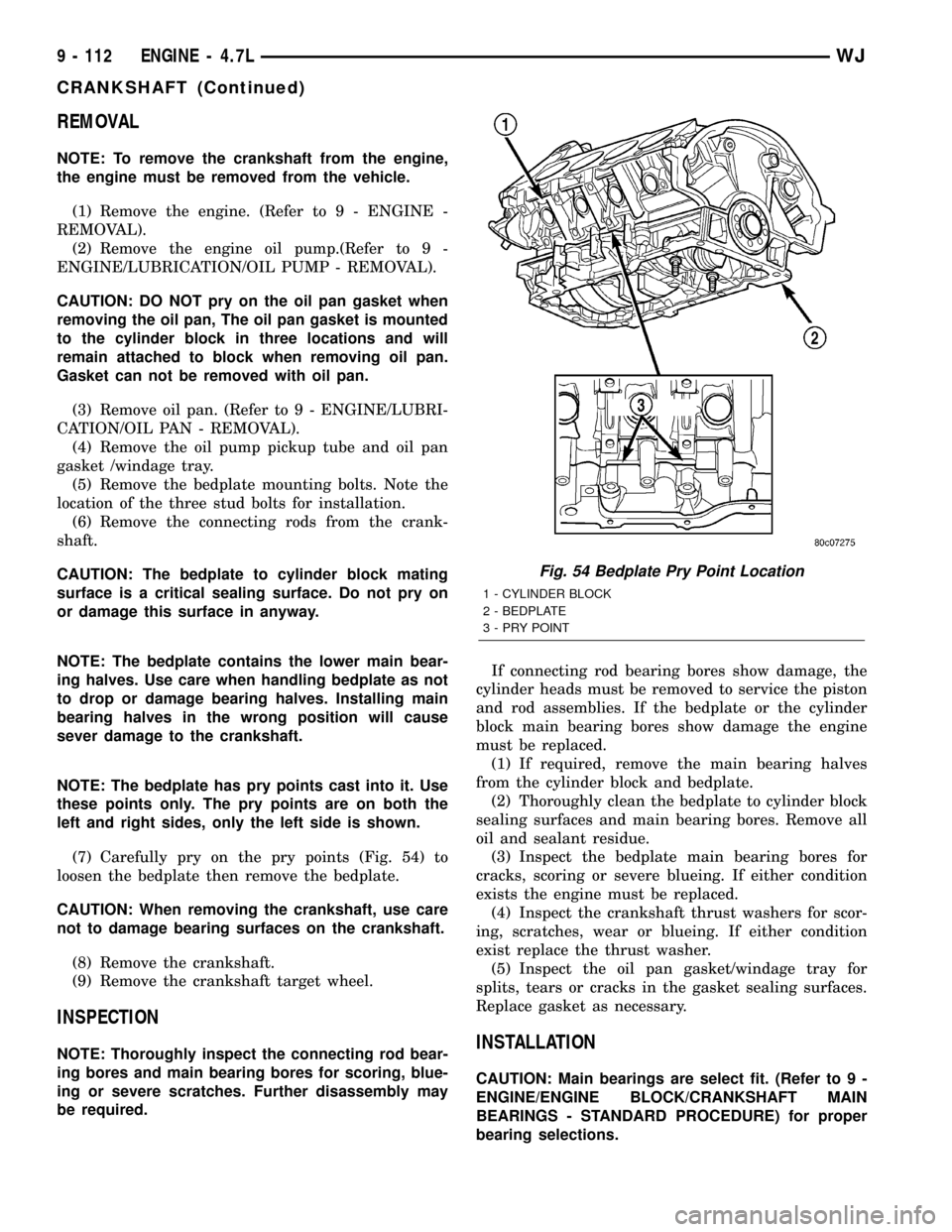
NOTE: The bedplate has pry points cast into it. Use
these points only. The pry points are on both the
left and right sides, only the left side is shown.
(7) Carefully pry on the pry points (Fig. 54) to
loosen the bedplate then remove the bedplate.
CAUTION: When removing the crankshaft, use care
not to damage bearing surfaces on the crankshaft.
(8) Remove the crankshaft.
(9) Remove the crankshaft target wheel.
INSPECTION
NOTE: Thoroughly inspect the connecting rod bear-
ing bores and main bearing bores for scoring, blue-
ing or severe scratches. Further disassembly may
be required.If connecting rod bearing bores show damage, the
cylinder heads must be removed to service the piston
and rod assemblies. If the bedplate or the cylinder
block main bearing bores show damage the engine
must be replaced.
(1) If required, remove the main bearing halves
from the cylinder block and bedplate.
(2) Thoroughly clean the bedplate to cylinder block
sealing surfaces and main bearing bores. Remove all
oil and sealant residue.
(3) Inspect the bedplate main bearing bores for
cracks, scoring or severe blueing. If either condition
exists the engine must be replaced.
(4) Inspect the crankshaft thrust washers for scor-
ing, scratches, wear or blueing. If either condition
exist replace the thrust washer.
(5) Inspect the oil pan gasket/windage tray for
splits, tears or cracks in the gasket sealing surfaces.
Replace gasket as necessary.INSTALLATION
CAUTION: Main bearings are select fit. (Refer to 9 -
ENGINE/ENGINE BLOCK/CRANKSHAFT MAIN
BEARINGS - STANDARD PROCEDURE) for proper
bearing selections.
Fig. 54 Bedplate Pry Point Location
1 - CYLINDER BLOCK
2 - BEDPLATE
3 - PRY POINT
9 - 112 ENGINE - 4.7LWJ
CRANKSHAFT (Continued)
Page 1363 of 2199
Check the connecting rod for signs of twist or bend-
ing.
Check the piston for taper and elliptical shape
before it is fitted into the cylinder bore (Refer to 9 -
ENGINE/ENGINE BLOCK/PISTON & CONNECT-
ING ROD - STANDARD PROCEDURE).
Check the piston for scoring, or scraping marks in
the piston skirts. Check the ring lands for cracks
and/or deterioration.
INSTALLATION
(1) Before installing piston and connecting rod
assemblies into the bore, install the piston rings.
(2)
Immerse the piston head and rings in clean
engine oil. Position a ring compressor over the piston
and rings. Tighten ring compressor.Ensure position
of rings do not change during this operation.
(3)Position bearing onto connecting rod. Ensure that
hole in bearing shell aligns with hole in connecting rod.
Lubricate bearing surface with clean engine oil.
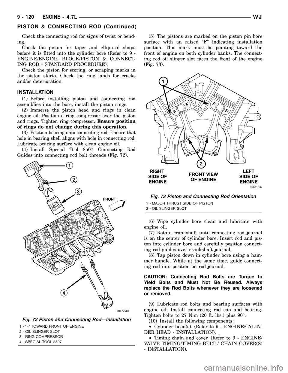
(4) Install Special Tool 8507 Connecting Rod
Guides into connecting rod bolt threads (Fig. 72).(5) The pistons are marked on the piston pin bore
surface with an raised ªFº indicating installation
position. This mark must be pointing toward the
front of engine on both cylinder banks. The connect-
ing rod oil slinger slot faces the front of the engine
(Fig. 73).
(6) Wipe cylinder bore clean and lubricate with
engine oil.
(7) Rotate crankshaft until connecting rod journal
is on the center of cylinder bore. Insert rod and pis-
ton into cylinder bore and carefully position connect-
ing rod guides over crankshaft journal.
(8) Tap piston down in cylinder bore using a ham-
mer handle. While at the same time, guide connect-
ing rod into position on rod journal.
CAUTION: Connecting Rod Bolts are Torque to
Yield Bolts and Must Not Be Reused. Always
replace the Rod Bolts whenever they are loosened
or removed.
(9) Lubricate rod bolts and bearing surfaces with
engine oil. Install connecting rod cap and bearing.
Tighten bolts to 27 N´m (20 ft. lbs.) plus 90É.
(10) Install the following components:
²Cylinder head(s). (Refer to 9 - ENGINE/CYLIN-
DER HEAD - INSTALLATION).
²Timing chain and cover. (Refer to 9 - ENGINE/
VALVE TIMING/TIMING BELT / CHAIN COVER(S)
- INSTALLATION).
Fig. 72 Piston and Connecting RodÐInstallation
1 - ªFº TOWARD FRONT OF ENGINE
2 - OIL SLINGER SLOT
3 - RING COMPRESSOR
4 - SPECIAL TOOL 8507
Fig. 73 Piston and Connecting Rod Orientation
1 - MAJOR THRUST SIDE OF PISTON
2 - OIL SLINGER SLOT
9 - 120 ENGINE - 4.7LWJ
PISTON & CONNECTING ROD (Continued)
Page 1366 of 2199
(3) Remove crankshaft damper bolt.
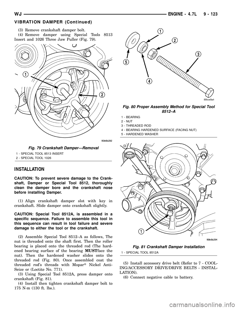
(4) Remove damper using Special Tools 8513
Insert and 1026 Three Jaw Puller (Fig. 79).
INSTALLATION
CAUTION: To prevent severe damage to the Crank-
shaft, Damper or Special Tool 8512, thoroughly
clean the damper bore and the crankshaft nose
before installing Damper.
(1) Align crankshaft damper slot with key in
crankshaft. Slide damper onto crankshaft slightly.
CAUTION: Special Tool 8512A, is assembled in a
specific sequence. Failure to assemble this tool in
this sequence can result in tool failure and severe
damage to either the tool or the crankshaft.
(2) Assemble Special Tool 8512±A as follows, The
nut is threaded onto the shaft first. Then the roller
bearing is placed onto the threaded rod (The hard-
ened bearing surface of the bearingMUSTface the
nut). Then the hardened washer slides onto the
threaded rod (Fig. 80). Once assembled coat the
threaded rod's threads with MopartNickel Anti-
Seize or (Loctite No. 771).
(3) Using Special Tool 8512A, press damper onto
crankshaft (Fig. 81).
(4) Install then tighten crankshaft damper bolt to
175 N´m (130 ft. lbs.).(5) Install accessory drive belt (Refer to 7 - COOL-
ING/ACCESSORY DRIVE/DRIVE BELTS - INSTAL-
LATION).
(6) Connect negative cable to battery.
Fig. 79 Crankshaft DamperÐRemoval
1 - SPECIAL TOOL 8513 INSERT
2 - SPECIAL TOOL 1026
Fig. 80 Proper Assembly Method for Special Tool
8512±A
1 - BEARING
2 - NUT
3 - THREADED ROD
4 - BEARING HARDENED SURFACE (FACING NUT)
5 - HARDENED WASHER
Fig. 81 Crankshaft Damper Installation
1 - SPECIAL TOOL 8512A
WJENGINE - 4.7L 9 - 123
VIBRATION DAMPER (Continued)
Page 1371 of 2199
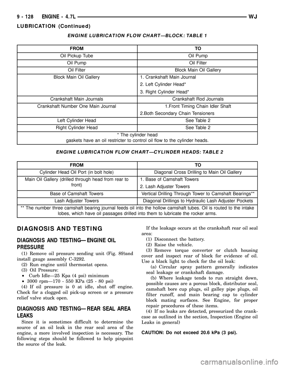
ENGINE LUBRICATION FLOW CHARTÐBLOCK: TABLE 1
FROM TO
Oil Pickup Tube Oil Pump
Oil Pump Oil Filter
Oil Filter Block Main Oil Gallery
Block Main Oil Gallery 1. Crankshaft Main Journal
2. Left Cylinder Head*
3. Right Cylinder Head*
Crankshaft Main Journals Crankshaft Rod Journals
Crankshaft Number One Main Journal 1.Front Timing Chain Idler Shaft
2.Both Secondary Chain Tensioners
Left Cylinder Head See Table 2
Right Cylinder Head See Table 2
* The cylinder head
gaskets have an oil restricter to control oil flow to the cylinder heads.
ENGINE LUBRICATION FLOW CHARTÐCYLINDER HEADS: TABLE 2
FROM TO
Cylinder Head Oil Port (in bolt hole) Diagonal Cross Drilling to Main Oil Gallery
Main Oil Gallery (drilled through head from rear to
front)1. Base of Camshaft Towers
2. Lash Adjuster Towers
Base of Camshaft Towers Vertical Drilling Through Tower to Camshaft Bearings**
Lash Adjuster Towers Diagonal Drillings to Hydraulic Lash Adjuster Pockets
** The number three camshaft bearing journal feeds oil into the hollow camshaft tubes. Oil is routed to the intake
lobes, which have oil passages drilled into them to lubricate the rocker arms.
DIAGNOSIS AND TESTING
DIAGNOSIS AND TESTINGÐENGINE OIL
PRESSURE
(1) Remove oil pressure sending unit (Fig. 89)and
install gauge assembly C-3292.
(2) Run engine until thermostat opens.
(3) Oil Pressure:
²Curb IdleÐ25 Kpa (4 psi) minimum
²3000 rpmÐ170 - 550 KPa (25 - 80 psi)
(4) If oil pressure is 0 at idle, shut off engine.
Check for a clogged oil pick-up screen or a pressure
relief valve stuck open.
DIAGNOSIS AND TESTINGÐREAR SEAL AREA
LEAKS
Since it is sometimes difficult to determine the
source of an oil leak in the rear seal area of the
engine, a more involved inspection is necessary. The
following steps should be followed to help pinpoint
the source of the leak.If the leakage occurs at the crankshaft rear oil seal
area:
(1) Disconnect the battery.
(2) Raise the vehicle.
(3) Remove torque converter or clutch housing
cover and inspect rear of block for evidence of oil.
Use a black light to check for the oil leak:
(a) Circular spray pattern generally indicates
seal leakage or crankshaft damage.
(b) Where leakage tends to run straight down,
possible causes are a porous block, distributor seal,
camshaft bore cup plugs, oil galley pipe plugs, oil
filter runoff, and main bearing cap to cylinder
block mating surfaces. See Engine, for proper
repair procedures of these items.
(4) If no leaks are detected, pressurized the crank-
case as outlined in the section, Inspection (Engine oil
Leaks in general)
CAUTION: Do not exceed 20.6 kPa (3 psi).
9 - 128 ENGINE - 4.7LWJ
LUBRICATION (Continued)
Page 1374 of 2199
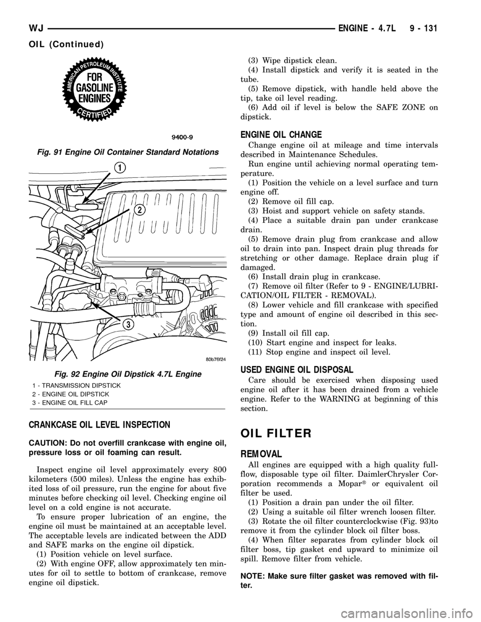
CRANKCASE OIL LEVEL INSPECTION
CAUTION: Do not overfill crankcase with engine oil,
pressure loss or oil foaming can result.
Inspect engine oil level approximately every 800
kilometers (500 miles). Unless the engine has exhib-
ited loss of oil pressure, run the engine for about five
minutes before checking oil level. Checking engine oil
level on a cold engine is not accurate.
To ensure proper lubrication of an engine, the
engine oil must be maintained at an acceptable level.
The acceptable levels are indicated between the ADD
and SAFE marks on the engine oil dipstick.
(1) Position vehicle on level surface.
(2) With engine OFF, allow approximately ten min-
utes for oil to settle to bottom of crankcase, remove
engine oil dipstick.(3) Wipe dipstick clean.
(4) Install dipstick and verify it is seated in the
tube.
(5) Remove dipstick, with handle held above the
tip, take oil level reading.
(6) Add oil if level is below the SAFE ZONE on
dipstick.
ENGINE OIL CHANGE
Change engine oil at mileage and time intervals
described in Maintenance Schedules.
Run engine until achieving normal operating tem-
perature.
(1) Position the vehicle on a level surface and turn
engine off.
(2) Remove oil fill cap.
(3) Hoist and support vehicle on safety stands.
(4) Place a suitable drain pan under crankcase
drain.
(5) Remove drain plug from crankcase and allow
oil to drain into pan. Inspect drain plug threads for
stretching or other damage. Replace drain plug if
damaged.
(6) Install drain plug in crankcase.
(7) Remove oil filter (Refer to 9 - ENGINE/LUBRI-
CATION/OIL FILTER - REMOVAL).
(8) Lower vehicle and fill crankcase with specified
type and amount of engine oil described in this sec-
tion.
(9) Install oil fill cap.
(10) Start engine and inspect for leaks.
(11) Stop engine and inspect oil level.
USED ENGINE OIL DISPOSAL
Care should be exercised when disposing used
engine oil after it has been drained from a vehicle
engine. Refer to the WARNING at beginning of this
section.
OIL FILTER
REMOVAL
All engines are equipped with a high quality full-
flow, disposable type oil filter. DaimlerChrysler Cor-
poration recommends a Mopartor equivalent oil
filter be used.
(1) Position a drain pan under the oil filter.
(2) Using a suitable oil filter wrench loosen filter.
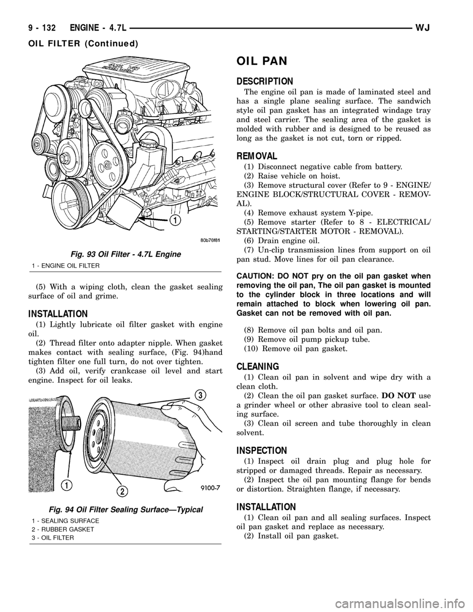
(3) Rotate the oil filter counterclockwise (Fig. 93)to
remove it from the cylinder block oil filter boss.
(4) When filter separates from cylinder block oil
filter boss, tip gasket end upward to minimize oil
spill. Remove filter from vehicle.
NOTE: Make sure filter gasket was removed with fil-
ter.
Fig. 91 Engine Oil Container Standard Notations
Fig. 92 Engine Oil Dipstick 4.7L Engine
1 - TRANSMISSION DIPSTICK
2 - ENGINE OIL DIPSTICK
3 - ENGINE OIL FILL CAP
WJENGINE - 4.7L 9 - 131
OIL (Continued)
Page 1375 of 2199
(5) With a wiping cloth, clean the gasket sealing
surface of oil and grime.
INSTALLATION
(1) Lightly lubricate oil filter gasket with engine
oil.
(2) Thread filter onto adapter nipple. When gasket
makes contact with sealing surface, (Fig. 94)hand
tighten filter one full turn, do not over tighten.
(3) Add oil, verify crankcase oil level and start
engine. Inspect for oil leaks.
OIL PAN
DESCRIPTION
The engine oil pan is made of laminated steel and
has a single plane sealing surface. The sandwich
style oil pan gasket has an integrated windage tray
and steel carrier. The sealing area of the gasket is
molded with rubber and is designed to be reused as
long as the gasket is not cut, torn or ripped.
REMOVAL
(1) Disconnect negative cable from battery.
(2) Raise vehicle on hoist.
(3) Remove structural cover (Refer to 9 - ENGINE/
ENGINE BLOCK/STRUCTURAL COVER - REMOV-
AL).
(4) Remove exhaust system Y-pipe.
(5) Remove starter (Refer to 8 - ELECTRICAL/
STARTING/STARTER MOTOR - REMOVAL).
(6) Drain engine oil.
(7) Un-clip transmission lines from support on oil
pan stud. Move lines for oil pan clearance.
CAUTION: DO NOT pry on the oil pan gasket when
removing the oil pan, The oil pan gasket is mounted
to the cylinder block in three locations and will
remain attached to block when lowering oil pan.
Gasket can not be removed with oil pan.
(8) Remove oil pan bolts and oil pan.
(9) Remove oil pump pickup tube.
(10) Remove oil pan gasket.
CLEANING
(1) Clean oil pan in solvent and wipe dry with a
clean cloth.
(2) Clean the oil pan gasket surface.DO NOTuse
a grinder wheel or other abrasive tool to clean seal-
ing surface.
(3) Clean oil screen and tube thoroughly in clean
solvent.
INSPECTION
(1) Inspect oil drain plug and plug hole for
stripped or damaged threads. Repair as necessary.
(2) Inspect the oil pan mounting flange for bends
or distortion. Straighten flange, if necessary.
INSTALLATION
(1) Clean oil pan and all sealing surfaces. Inspect
oil pan gasket and replace as necessary.
(2) Install oil pan gasket.
Fig. 93 Oil Filter - 4.7L Engine
1 - ENGINE OIL FILTER
Fig. 94 Oil Filter Sealing SurfaceÐTypical
1 - SEALING SURFACE
2 - RUBBER GASKET
3 - OIL FILTER
9 - 132 ENGINE - 4.7LWJ
OIL FILTER (Continued)
Page 1390 of 2199
TIMING BELT/CHAIN AND
SPROCKETS
REMOVAL
(1) Disconnect negative cable from battery.
(2) Drain cooling system (Refer to 7 - COOLING -
STANDARD PROCEDURE).
(3) Remove right and left cylinder head covers
(Refer to 9 - ENGINE/CYLINDER HEAD/CYLIN-
DER HEAD COVER(S) - REMOVAL).
(4) Remove radiator fan (Refer to 7 - COOLING/
ENGINE/RADIATOR FAN - REMOVAL).
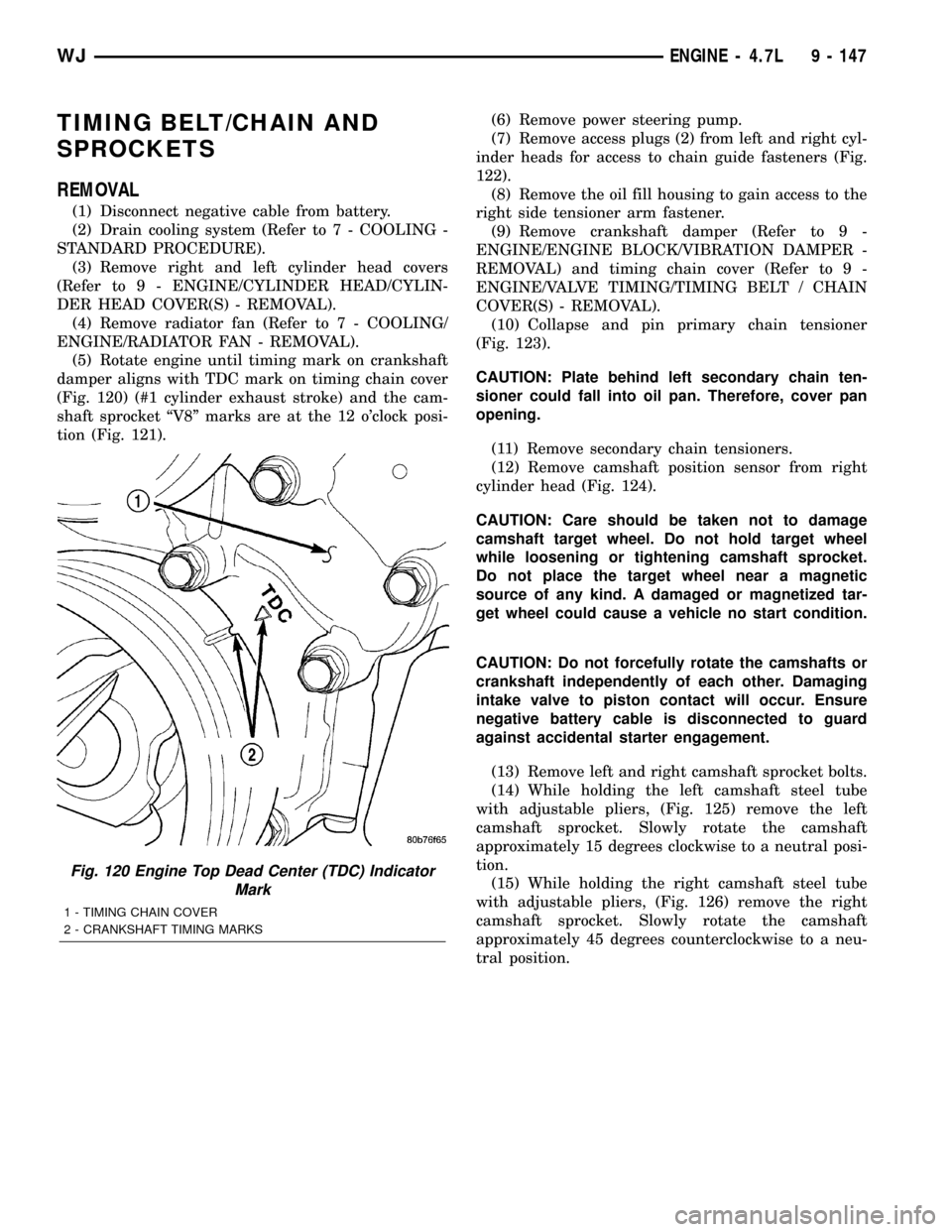
(5) Rotate engine until timing mark on crankshaft
damper aligns with TDC mark on timing chain cover
(Fig. 120) (#1 cylinder exhaust stroke) and the cam-
shaft sprocket ªV8º marks are at the 12 o'clock posi-
tion (Fig. 121).(6) Remove power steering pump.
(7) Remove access plugs (2) from left and right cyl-
inder heads for access to chain guide fasteners (Fig.
122).
(8) Remove the oil fill housing to gain access to the
right side tensioner arm fastener.
(9) Remove crankshaft damper (Refer to 9 -
ENGINE/ENGINE BLOCK/VIBRATION DAMPER -
REMOVAL) and timing chain cover (Refer to 9 -
ENGINE/VALVE TIMING/TIMING BELT / CHAIN
COVER(S) - REMOVAL).
(10) Collapse and pin primary chain tensioner
(Fig. 123).
CAUTION: Plate behind left secondary chain ten-
sioner could fall into oil pan. Therefore, cover pan
opening.
(11) Remove secondary chain tensioners.
(12) Remove camshaft position sensor from right
cylinder head (Fig. 124).
CAUTION: Care should be taken not to damage
camshaft target wheel. Do not hold target wheel
while loosening or tightening camshaft sprocket.
Do not place the target wheel near a magnetic
source of any kind. A damaged or magnetized tar-
get wheel could cause a vehicle no start condition.
CAUTION: Do not forcefully rotate the camshafts or
crankshaft independently of each other. Damaging
intake valve to piston contact will occur. Ensure
negative battery cable is disconnected to guard
against accidental starter engagement.
(13) Remove left and right camshaft sprocket bolts.
(14) While holding the left camshaft steel tube
with adjustable pliers, (Fig. 125) remove the left
camshaft sprocket. Slowly rotate the camshaft
approximately 15 degrees clockwise to a neutral posi-
tion.
(15) While holding the right camshaft steel tube
with adjustable pliers, (Fig. 126) remove the right
camshaft sprocket. Slowly rotate the camshaft
approximately 45 degrees counterclockwise to a neu-
tral position.
Fig. 120 Engine Top Dead Center (TDC) Indicator
Mark
1 - TIMING CHAIN COVER
2 - CRANKSHAFT TIMING MARKS
WJENGINE - 4.7L 9 - 147
Page 1393 of 2199
body. Install Special Tool 8514 lock pin into hole on
front of tensioner. Slowly open vise to transfer piston
spring force to lock pin (Fig. 128).
(2) Position primary chain tensioner over oil pump
and insert bolts into lower two holes on tensioner
bracket. Tighten bolts to 28 N´m (250 in. lbs.).
CAUTION: Overtightening the tensioner arm torxT
bolt can cause severe damage to the cylinder head.
Tighten torxTbolt to specified torque only.
(3) Install right side chain tensioner arm. Apply
MopartLock N, Seal to torxtbolt, tighten bolt to 17
N´m (150 in. lbs.).
NOTE: The silver bolts retain the guides to the cyl-
inder heads and the black bolts retain the guides to
the engine block.(4) Install the left side chain guide. Tighten the
bolts to 28 N´m (250 in. lbs.).
CAUTION: Overtightening the tensioner arm torxT
bolt can cause severe damage to the cylinder head.
Tighten torxTbolt to specified torque only.
(5) Install left side chain tensioner arm. Apply
MopartLock N, Seal to torxtbolt, tighten bolt to 17
N´m (150 in. lbs.).
(6) Install the right side chain guide. Tighten the
bolts to 28 N´m (250 in. lbs.).
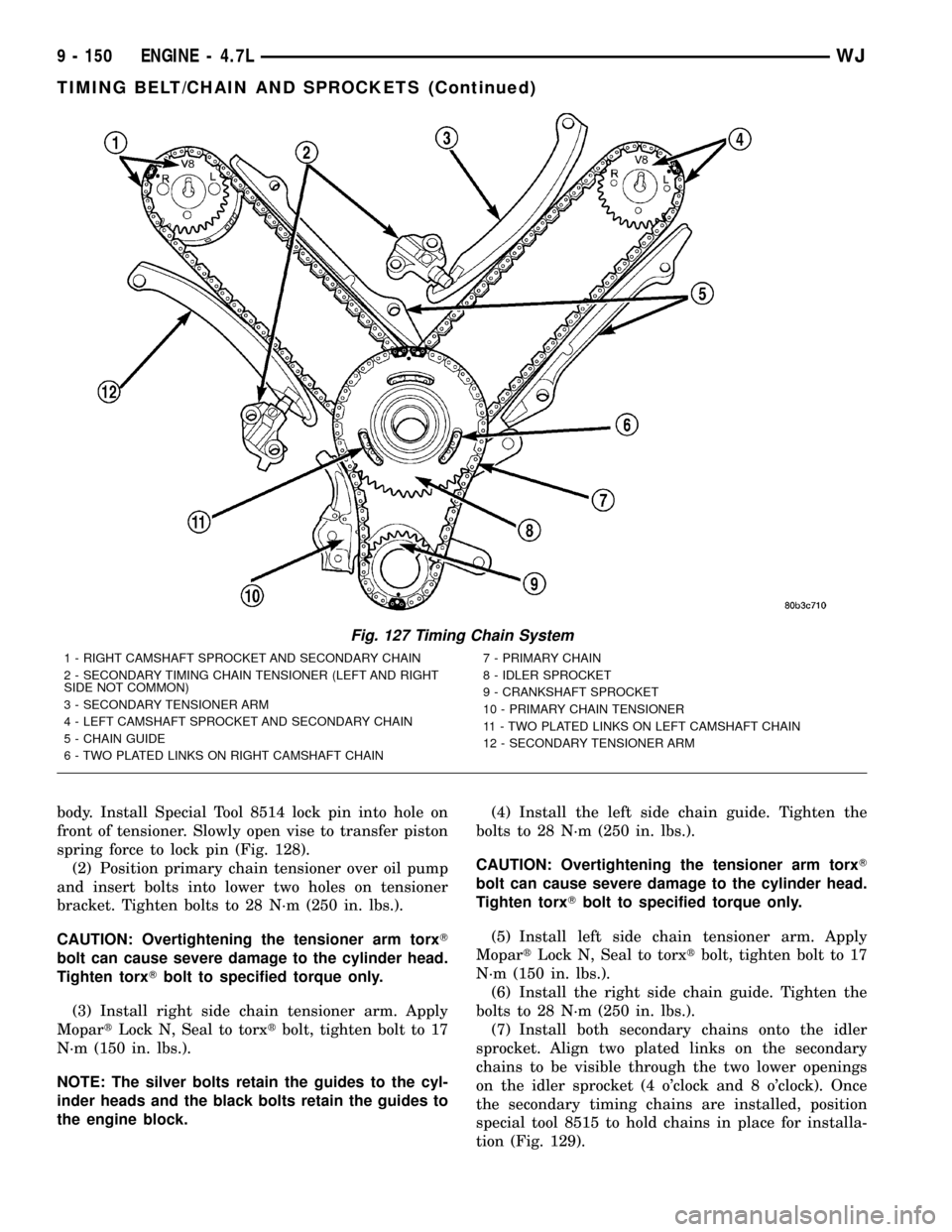
(7) Install both secondary chains onto the idler
sprocket. Align two plated links on the secondary
chains to be visible through the two lower openings
on the idler sprocket (4 o'clock and 8 o'clock). Once
the secondary timing chains are installed, position
special tool 8515 to hold chains in place for installa-
tion (Fig. 129).
Fig. 127 Timing Chain System
1 - RIGHT CAMSHAFT SPROCKET AND SECONDARY CHAIN
2 - SECONDARY TIMING CHAIN TENSIONER (LEFT AND RIGHT
SIDE NOT COMMON)
3 - SECONDARY TENSIONER ARM
4 - LEFT CAMSHAFT SPROCKET AND SECONDARY CHAIN
5 - CHAIN GUIDE
6 - TWO PLATED LINKS ON RIGHT CAMSHAFT CHAIN7 - PRIMARY CHAIN
8 - IDLER SPROCKET
9 - CRANKSHAFT SPROCKET
10 - PRIMARY CHAIN TENSIONER
11 - TWO PLATED LINKS ON LEFT CAMSHAFT CHAIN
12 - SECONDARY TENSIONER ARM
9 - 150 ENGINE - 4.7LWJ
TIMING BELT/CHAIN AND SPROCKETS (Continued)