Page 217 of 312

CONTROLS AND EQUIPMENT
1- 36 The windscreen wiper switch, dependent upon
model, has three operating positions.
1. Intermittent wiper operation.
(Not all models)
2. Low speed operation.
3. High speed operation.
NOTE: To prevent damage to the wiper system,
do not attempt to wipe away heavy accu-mulations of snow or ice.
Accumulated snow and ice should be
removed manually. If there is only a lightlayer of snow or ice, operate the heater inthe defrost mode to melt the snow or icebefore using the wiper. SB230A1-E
WINDSCREEN WIPER/WASHER SWITCH
SB220E1-E HEADLIGHT FLASH The headlights may be flashed by pulling the turn signal switch lever towards the steeringwheel. The headlights will be extinguishedwhen the switch is released.
SB220D1-E HIGH AND LOW BEAM To turn on the headlight high beams, push the lever forward (away from you). For low beams,pull the lever back (toward you). The appropri-ate headlight beam indicator light will come onat the same time.
B340E01FC-D
B350A01O-D
(1)
(2)
(3)
B350B01O-EAT
Windscreen Washer Operation
To use the windscreen washer, pull the wiper/
washer lever toward the steering wheel. When the washer lever is operated, the wipers auto-matically make two passes across thewindscreen. The washer continues to operateuntil the lever is released.
NOTE:
o Do not operate the washer more than 15 seconds at a time or when the fluidreservoir is empty.
o In icy or freezing weather, be sure the wiper blades are not frozen to the glassprior to operating the wipers.
o In areas where water freezes in winter, use windscreen washer antifreeze. B350B01O-DAG
Page 218 of 312

1- 37
CONTROLS AND EQUIPMENTSB240A1-E
HAZARD WARNING SYSTEM
The hazard warning system should be used
whenever it becomes necessary to stop the car in a hazardous location. The hazard warn-ing system is operated by depressing theswitch at which time all turn signal lights willflash simultaneously and the turn signal warn-ing lights located within the instrument clusterwill flash simultaneously.
The hazard warning system may be turned off
by depressing the switch again.
B350C01FC-DAT Adjustable Intermittent Wiper Operation To use the intermittent wiper feature, place
the wiper switch in the "INT" position. With the switch in this position, the interval betweenwipes can be varied from approximately 1 to18 seconds by turning the interval adjusterbarrel.
Mist Wiper Operation If a single wipe is desired in mist, push the windscreen wiper and washer control leverupwards. B350A01O-AAT
Tail Gate Wiper And Washer Switch
1. :The washer fluid will be sprayed onto
the rear window and the wiper oper- ates while the rear window wiper barrelis placed in this position.
2.OFF
3.INT :To use the intermittent wiper feature, place the rear window wiper barrel in the "INT" position.
4.ON :When the point indicates "ON", the rear window wiper operates continu-ously.
B350B02O-DAG
B350C01O-DAG
B350D01O-DAG
HFC2078-D
Page 219 of 312

CONTROLS AND EQUIPMENT
1- 38 NOTE: The engine must be running for the heated rear window to operate.
SB250A1-E HEATED REAR WINDOW To operate the heated rear window depress the switch shown. The heated rear windowwill automatically turn off after 20 minutes orwhen the ignition is turned off. The system may be turned off manually by depressing the switch again. CAUTION: The inside of the rear windscreen shouldnever be cleaned with a hard or sharp imple-ment since damage to the heating elementmay occur. The glass should only be cleanedwith a soft cloth or chamois leather with theuse only of a mild detergent or proprietaryglass cleaner where necessary. Only hori-zontal movement of the cloth should bemade when cleaning the glass and careshould be exercised to ensure that the heat-ing elements are not damaged by rings orjewellery whilst the glass is being cleaned. B360A01Y-GAT
REAR FOG LIGHT SWITCH
To turn on the rear fog lights, push the switch.
They will come on when the headlight switchis in the second position and the key is in the"ON" position.
HFC2080-D
B360B01FC-1
B360B01FC-EAT FRONT FOG LIGHT SWITCH (Not all models) To turn on the front fog lights, push the switch in the "ON" position. They will come on whenthe headlight switch is in the first or secondposition.
B360A01FC-1
Page 220 of 312

1- 39
CONTROLS AND EQUIPMENTSB290A02-F CIGAR LIGHTER For the cigar lighter to work, the key must be in the "ACC" or the "ON" position.To use the cigar lighter, push the lighter all theway into its socket. When the element isheated, the lighter will pop out into the "ready"position. Do not hold the cigar lighter at the depressed position which may result in damage to thevehicle wiring or an electrical fire. If it is necessary to replace the cigarette lighter, use only a genuine Hyundai replace-ment part. CAUTION: Do not use electric accessories or equip- ment other than the Hyundai genuine partsin the socket. The front ashtray may be opened by pulling itup by its top edge. To remove the ashtray toempty or clean it, pull the cover up all the wayout. The ashtray light will only illuminate whenthe external lights are on.
B430A01FC-GAT FRONT ASHTRAY
There are three control buttons for the digital clock. Their functions are: HOUR - Push "H" to advance the hour indicat-
ed. MIN - Push "M" to advance the minute indicat-
ed.RESET - Push "R" to reset minutes to ":00" to
facilitate resetting the clock to the correct time. When this is done: Pressing "R" between 10 : 30 and 11 : 29 changes the readout to 11 : 00. Pressing "R" between 11 : 30 and 12 : 29 changes the readout to 12 : 00.
B400A01A-AAT DIGITAL CLOCK
B420A01FC-DHFC2091HFC2056-D
Page 221 of 312

CONTROLS AND EQUIPMENT
1- 40
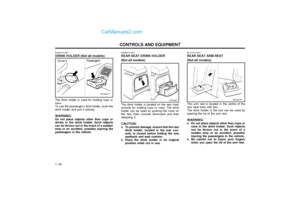
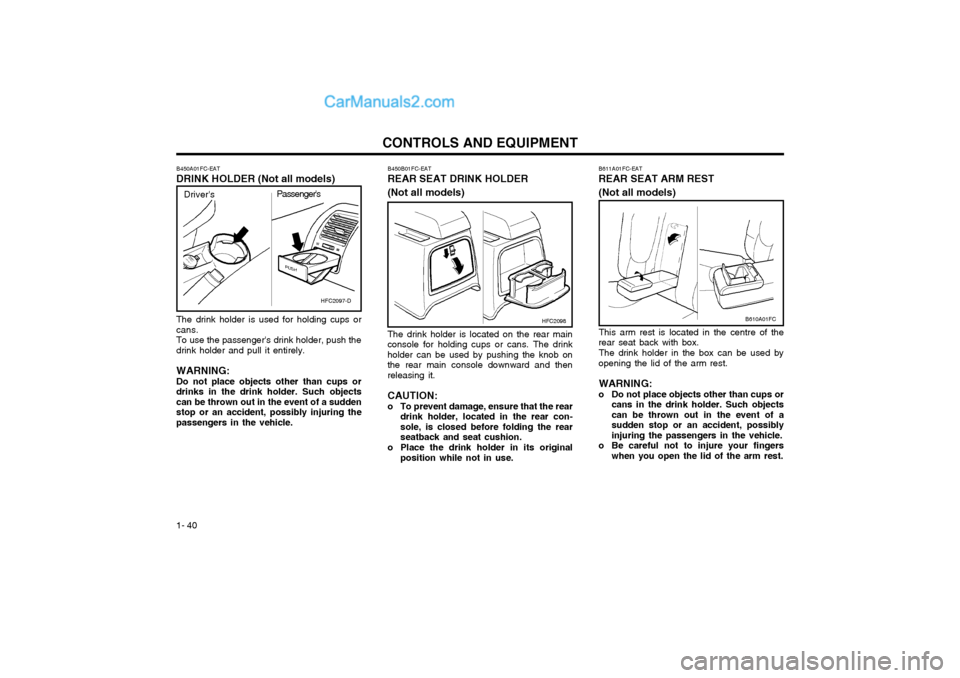
The drink holder is used for holding cups or cans.To use the passenger's drink holder, push thedrink holder and pull it entirely. WARNING: Do not place objects other than cups or drinks in the drink holder. Such objectscan be thrown out in the event of a suddenstop or an accident, possibly injuring thepassengers in the vehicle.
B450A01FC-EAT DRINK HOLDER (Not all models)
B450B01FC-EAT
REAR SEAT DRINK HOLDER (Not all models)
The drink holder is located on the rear main
console for holding cups or cans. The drink holder can be used by pushing the knob onthe rear main console downward and thenreleasing it.
CAUTION:
o To prevent damage, ensure that the rear drink holder, located in the rear con-sole, is closed before folding the rearseatback and seat cushion.
o Place the drink holder in its original position while not in use.
HFC2097-D
Driver's Passenger's
HFC2098
B611A01FC-EAT REAR SEAT ARM REST (Not all models)
This arm rest is located in the centre of the
rear seat back with box.
The drink holder in the box can be used by
opening the lid of the arm rest.
WARNING:
o Do not place objects other than cups or cans in the drink holder. Such objects can be thrown out in the event of asudden stop or an accident, possiblyinjuring the passengers in the vehicle.
o Be careful not to injure your fingers when you open the lid of the arm rest.
B610A01FC
Page 222 of 312

1- 41
CONTROLS AND EQUIPMENTSB330A1-E SUNROOF (Not all models)
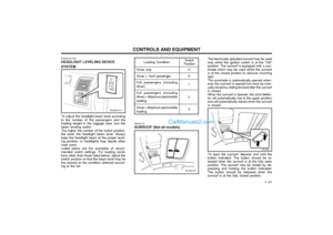
To adjust the headlight beam level according
to the number of the passengers and the loading weight in the luggage area, turn thebeam leveling switch.
The higher the number of the switch position,
the lower the headlight beam level. Alwayskeep the headlight beam at the proper level-ing position, or headlights may dazzle otherroad users.
Listed below are the examples of recom-
mended switch settings. For loading condi-tions other than those listed below, adjust theswitch position so that the beam level may bethe nearest as the condition obtained accord-ing to the list.
Switch
PositionLoading Condition
Driver only Driver + front passengerFull passengers (including
driver)
Full passengers (including
driver) + Maximum permissible loading
Driver + Maximum permissible
loading 0 0 1 2 3
B340G01FC-EAT HEADLIGHT LEVELING DEVICE SYSTEM
The electrically operated sunroof may be used
only whilst the ignition switch is at the "ON" position. The sunroof is equipped with a sun-shade which may be used whilst the sunroofis at the closed position to obscure incominglight.
The sunshade is automatically opened when-
ever the sunroof is opened but must be man-ually closed by sliding forward after the sunroofis closed.
When the sunroof is opened, the wind deflec-
tor will automatically rise to the upper positionand will automatically retract when the sunroofis closed. To open the sunroof, depress and hold the button indicated. The button should be re-leased when the sunroof is at the fully openposition. The sunroof may be closed by de-pressing and holding the button indicated.The button should be released when thesunroof is at the fully closed position.
HFC2021
B470A01FC
B340G01FC-1
Page 223 of 312

CONTROLS AND EQUIPMENT
1- 42
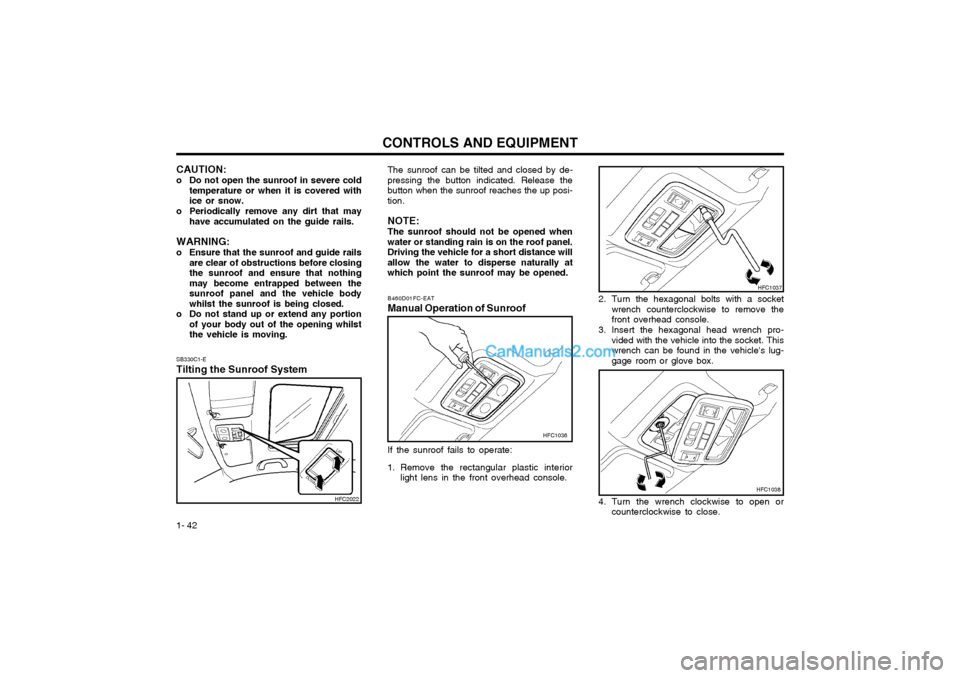
SB330C1-E Tilting the Sunroof System The sunroof can be tilted and closed by de-
pressing the button indicated. Release the button when the sunroof reaches the up posi-tion.
NOTE: The sunroof should not be opened when
water or standing rain is on the roof panel. Driving the vehicle for a short distance willallow the water to disperse naturally atwhich point the sunroof may be opened.
2. Turn the hexagonal bolts with a socketwrench counterclockwise to remove thefront overhead console.
3. Insert the hexagonal head wrench pro- vided with the vehicle into the socket. Thiswrench can be found in the vehicle's lug-gage room or glove box.
B460D01FC-EAT
Manual Operation of Sunroof
HFC1036
If the sunroof fails to operate:
1. Remove the rectangular plastic interior light lens in the front overhead console.
HFC1037
4. Turn the wrench clockwise to open or counterclockwise to close.
CAUTION:
o Do not open the sunroof in severe cold
temperature or when it is covered with ice or snow.
o Periodically remove any dirt that may have accumulated on the guide rails.
WARNING:
o Ensure that the sunroof and guide rails are clear of obstructions before closing the sunroof and ensure that nothingmay become entrapped between thesunroof panel and the vehicle bodywhilst the sunroof is being closed.
o Do not stand up or extend any portion of your body out of the opening whilstthe vehicle is moving.
HFC2022HFC1038
Page 224 of 312

1- 43
CONTROLS AND EQUIPMENTThe interior courtesy light has a button of three positions. The three positions are:
oDR In the "DR" position, the interior courtesy light comes on when any door is opened regard-less of the ignition key position. The light goesout when the door is closed.
oON In the "ON" position, the light stays on at all times.
o OFF In the "OFF" position, the light stays off at all times even though a door is open.
SB340B1-E Interior Light
B490A01E
With Sunroof
Without Sunroof
B490B01E
B491A02F-EAT
SPECTACLE CASE (Not all models)
HXDOM241
The spectacle case is located on the front
overhead console. Push the end of the cover to open the spec-
tacle case.
WARNING: Do not open the spectacle case whilst the
vehicle is moving. The rear view mirror of the vehicle can be blocked by an openspectacle case.
B480A01E-EAT INTERIOR LIGHT Map Light The two map lights are located at each side of the interior light. The lights may be operated by depressing the switch to turn on the light and pressing againto turn off the light. This light produces a spotbeam for convenient use as a map light atnight or as a personal light for the driver or thepassenger.
B480A01EB480B01E
With Sunroof Without Sunroof