2003 HONDA CIVIC limit
[x] Cancel search: limitPage 831 of 1139

\Body Electrical
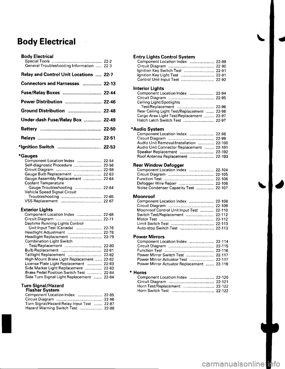
Body ElectricalSpecialToolsGeneral Troubleshooting tntorrnaiion.'......
Relay and Control Unit Locations .....
Connectors and Harnesses
Fuse/Relay Boxes ...............................
Power Distribution .............................
Ground Distribution ...........................
Under-dash Fuse/Relay Box ..............
Battery ..............
Relays ................
*lgnition Switch ..............
*Gauges
Component Location Index .......................Self-diagnostic Procedure ..........................Circuit DiagramGauge Bulb Replacement ..........................Gauge Assembly ReplacementCoolant Temperature
Gauge Troubleshooting .... ....................Vehicle Speed Signal CircuitTroubleshootingVSS Replacement
Exterior LightsComponent Location Index .......................Circuit DiagramDaytime Running Lights ControiUnit Input Test (Canada) ........................Headlight Ad,ustment .................. .. .....Headlighr Replacement ..............................Combination Light SwitchTest/ReplacementBulb ReplacementTaillight Replacement ..........................High Mount Brake Light Replacement ......License Plate Light Replacement ..............Side Marker Light Replacement ................Brake Pedal Position Switch Test ..............Side Turn Signal Light Replacement ........
Turn Signal/HazardFlasher SystemComponent Location Index .......................Circuit DiagramTurn Signal/Hazard Relay lnputTest ........Hazard Warning Switch Test
22,3
22-7
22-13
22-44
22-46
22-4A
22-49
22-50
22-51
22-53
22-5422-5622-5422 6322-64
22-64
22-6522 61
22-6822--71
22-7 622-7422-79
22-AO22-4122-8222-4222-4322-4322-4422-84
22-8�522 A622-8722-88
22-10422-105
22-10622-107
Entry Lights control systemComponent Location Index ....................... 22-89Circuit Diagram ......... 22 90lgnition Key Switch Test .....................,...... 22-9'llgnition Key Light Test ............................... 22-91Control Unit Input Test ..........,.................... 22 92
Interior LightsComponent Location Index ....................... 22-94Circuit Diagram ......... 22-95Ceiling LighVSpotlightsTesVReplacement ................................... 22-96Rear Ceiling Light TesVReplacem ent ........ 22-96Cargo Area Light Test/Replacem ent ......... 22-97Hatch Latch Switch Test ..,..,....................... 22-97
*Audio SystemComponent Location Index ....................... 22-98Circuit Diagram ......... 22,99Audio Unit Removal/lnstallation ............... 22-1OOAudio Unit Connector Replacement ......... 22-101Speaker Replacement ................................ 22-102Roof Antenna Rep1acement ....................-.. 22-103
Rear Window DefoggerComponent Location Index ...........Circuit Diasram .. ....... .. ..... ....... ...:::::.::.::.Function TestDefogger Wire Repair .................................Noise Condenser CapacityTest ................
MoonroofComponent Location Index ....................... 22-1OBCircuit Diagram ......... 22-109Moonroof Control Unit Input Test ............. 22-'l10Switch TesVReplacement ........,.....,........... 22-1 12Motor Test ................. 22-112Limit Swilch Test ...... 22-'l'13Auto-stop Switch Test ................................ 22-1 13
Power MirrorsComponent Location Index ....................... 22-114Circuit Diagram ......... 22-115Function Test ............. 22-116Power Mirror Switch Test .......................... 22-ll7Power Mirror Actuator Test ....................... 22-117Power Mirror Actuator Replacement ........ 22-11A
* HornsComponent Location Index ....................... 22-120Circuit Diagram ......... 22-121Horn TesVReplacement ...........................-. 22-122Horn Switch Test .,.... 22-122
\
Page 939 of 1139

Moonroof
Component Location Index
MOONROOF CONTROL UNITInput Test, page 22-'l10
MOONROOF SWITCHf e$, page 22-112Replacement, page 22-1 12
Test. page22-112Replacement, page 20-41
MOONROOF LIMIT SWITCHTest, page 22-113
\|.
MOONROOF AUTO-STOP SWITCHTest, page 22'113MOONROOF OPEN RELAY
lwire colors: GRN/YEL, GRN, ILRED/YEL, BLK and YEUGRN ITest, page 22-51MOONROOF CLOSE RELAY
lwire colorsr GRN/BLK, GRN, ILGRN/WHT, BLK and YEL/GRN ITest, page 22-51
22-108
Page 944 of 1139

l.
2.
Limit Switch Test
Remove the headliner (see page 20-54).
Disconnect the 4P connector from the moonroof
limit switch.
Check for continuily between the terminals in each
switch position according to the table.
NOTE: Turn the motor by hand with the wrench.
Terminal
Position134
TILTo-o-
OPEN
CLOSE
lf the continuity is not as specified, replace the
moonroof limit switch.
1.
2.
Auto-stop Switch Test
Remove the headliner (see page 20-54).
Disconnect the 2P connector from the moonroof
auto-stop switch.
Check for continuity between the terminals in each
switch position according to the table.
NOTE:. Turn the motor by hand with the wrench,. The auto-stop position is about 145 mm (5.75 in.)
from fully closed.
Position
Terminal12
Botwoen AUTO-STOPand CLOSE
Between OPEN andAUTO.STOP
lf the continuity is not as specified, repair or replace
the auto-stop switch.
22-113
Page 992 of 1139

Transmitter Test
NOTE:. lf the doors unlockorlockwiththetransmitter, but
the LED on the transmitter does not come on, the LED
is faulty. Replace the transmitter,. lf anydoor isopen, you cannotlockthedoorwiththe
transmrtter.. lf you unlocked the doors with the transmitter, but do
not open any of the doors within 30 seconds, the
doors relock automatically.. The doors do not lock or unlock with the transmitter if
the ignition key is inserted in the ignition switch.
1. Press the lock or unlock button five or six times to
reset the transmitter.
. lf the locks work, the transmitter is OK.. lf the locks don't work, go to step 2.
2. Open the transmitter and check for water damage.
. lf you find any water damage, replace the
transmrtter.. lf there is no waterdamage, go to step 3.
3. Replace the transmitter battery (A) with a new one,
and try to lock and unlock the doors with the
transmitter by pressing the lock or unlock button
five or six times.
. lf the doors lock and unlock, the transmifter is OK.. lf the doors don't lock and unlock, go to step 4.
Reprogram the transmitter, then try to lock and
unlock the doors.
. lf thedoors lockand unlock.thetransmitter is OK.. lf the doors don'tlockand unlock, replacethe
transmitter.
4.
Transmitter Programming
Storing transmitter codes:
The codes of up to three transmitters can be stored in
the keyless receiver unit memory. (lf a fourth code is
stored. the code which was input first will be erased.)
NOTE: lt is important to maintain the time limits
between the steps. Make sure the doors and the hatch
are closed.
1. Turn the ignition switch ON (lli.
2. Within 1 to 4 sec., push the transmitter lock or
unlock button with the transmitter aimed at the
receiver in the multiplex control unit behind the
driver's side of the dash.
3. Within 1 to 4 sec., turn the ignition switch OFF.
4. Within 1 to 4 sec., turn the ignition switch ON (ll).
5. Within 'l to 4 sec., push the transmitter lock or
unlock button with the transmitter aimed at the
receiver in the multiplex control unit behind the
driver's side of the dash.
6. Within 1 to 4 sec., turn the ignition switch OFF.
7. Within 4 sec., turn the ignition switch ON (ll).
8. Within 1 to 4 sec., push the transmitter lock or
unlock button with the transmifter aimed at the
receiver in the mupltiplex control unit behind the
driver's side of the dash.
9. Within 1 to 4 sec., turn the ignition switch OFF,
'10. Within 4 sec., turn the ignition switch ON (ll).
11. Within 1 to 4 sec., push the transmitter lock or
unlock button with the transmitter aimed at the
receiver in the multiplex control unit behind the
driver's side of the dash.
12. Confirm you can hearthe sound ofthe door lock
actuators. Within 1 to 4 sec., push the transmitter
lock or unlock button again,
13, Within 10 sec., aim the transmitters (up to two
additional ones) whose codes you want to store at
the receiver, and press the transmitter lock or
unlock buttons.
Confirm that you can hear the sound of the door
lock actuators after each transmitter code is stored.
14. Turn the ignition switch OFF, and pull out the key.
'15. Confirm proper operation ofthe transmitter.
22-161
Page 1038 of 1139

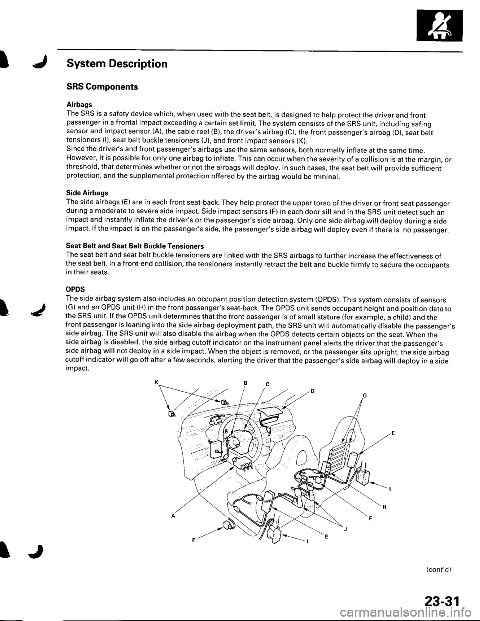
ISystem Description
SRS Components
Airbags
The SRS is a safety device which, when used with the seat belt, is designed to help protect the driver and frontpassenger in a frontal impact exceeding a certain set limit. The system consists ofthe SRS unit, including safingsensor and impact sensor (A), the cable reel (B), the driver's airbag (C), the front passenger,s airbag (D). seat belttensioners (l), seat belt buckle tensioners (J), and front impact sensors (K).
Since the driver's and front passenger's airbags use the same sensors, both normally inflate at the same ttme.However, it is possible for only one airbag to inflate. This can occur when the severity of a collision is at the margin, orthreshold, that determines whether or not the airbags will deploy. In such cases, the seat belt will provide sufficientprotection, and the supplemental protection offered by the airbag would be mininal.
Side Airbags
The side airbags (E) are in each front seat-back. They help protect the upper torso of the driver or front seat passenger
during a moderate to severe side impact. Side impact sensors (F) in each door sill and in the SRS unit detect such animpact and instantly inflate the driver's or the passenger's side airbag. Only one side airbag will deploy during a sideimpacl. lf the impact is on the passenger's side, the passenger's side airbag will deploy even if there is no passenger.
Seat Belt and Seat Belt Buckle Tensioners
The seat belt and seat belt buckle tensioners are linked with the SRS airbags to further increase the effectiveness ofthe seat belt. ln a front-end collision, the tensioners instantly retract the belt and buckle firmly to secure the occupantsin their seats.
OPDS
The side airbag system also includes an occupant position detection system (OpDS). This system consists of sensors(G)and an OPDS unit (H) in the front passenger's seat-back. The OPDS unit sends occupant heighl and position data tothe SRS unit. lf the OPDS unit determines that the front passenger is of small stature (for example, a child) and thefront passenger is leaning into the side airbag deployment path, the SRS unit will automatically disable the passenger'sside airbag. The SRS unit will also disable the airbag when the OPDS detects certain obiects on the seat. When theside airbag is disabled, the side airbag cutoff indicator on the instrument panel alerts the driver that the passenger'sside airbag will not deploy in a side impact. When the object is removed, or the passenger sits upright, the side airbagcutoff indicator will go off after a few seconds, alerting the driver that the passenger's side airbag will deploy in a sideimDact.
(cont'd)
I
23-31
Page 1137 of 1139

)
Low Fuel lndicatorTest.....................11-158Moonroof Drain Channel SliderReplacement......................................... 20'44
Moonroof FrameRep1acement,,,,,,,,,,.,.,.,.,.,.,.,,,,,,............ 20 42
MoonroolGlassAdiustment ........................................... 20-37Rep1acement......................................... 20 37
Moonroot Limit SwitchAdjustment ........................................-.- 20 46Test ...................................................... 22 113
Moonrool MotorReplacement....-.................................... 2D-41
Oil Pressure SwitchTest ................-.-........-................................ 8-4Replacement.........-................................. 8-16
Oil Pump, EngineOverhau1 ................................................... 8-8
Oil, EngineReplacement...-................-.-...................... 8-5
OPDS UnitReplacement....................................... 23- 124
Outside Mirror HoldersBeplacement......................................... 20-15
Outside Power Mirror ActuatorsTest ...................................................... 22-117Bepf acement..-.................................... 22-1 14
Outside Power Mirror SwitchTest ..-................................................... 22-111
Outsid€ Power MirrorsReplacement............................ ... .. . . . 20-15Component Location lndex .............. 22- 114Circuit Diagram .................................. 22-115Test -..................................................... 22-116
Lower ArmsRemoval/1nsta11ation............................ 18 19
Lubrication SystemComponent Location Index..................... 8-3Test............................................................ 8 4
M
M/TAssemblyRemoval.......... 13-4 Test...................... 22-1 12lnstallation............. 13-8
.........21,35
Disassembly ......................................... 13-14Resassembly .. ... ................. 13-46
M/TChange Leverlnspection ............................................. 13-19Disassembly 8eassemb1y ................... 13-20
M/T Countershaft AssemblyInspection ....................................... 13 31, 33Disassemb1y ......................................... 13-32Resassemb|y ........................................ 13-34
M/T DifferentialComponentLocation Index................. 13-52Adiuslment ........................................... 13-56
M/T Maifthaft Assembly1nspection ... ................................... 13-23, 26Disassembly ......................................... 13 25Resassembly ........................................ 13 28Adjustment ........................................... 13-43
M/T Reverse Shift ForkInspection .................... ........................ l3 19
M/T Shift LevelReplacement......................................... 13-51
Mainshaft BearingsReplacement....,.................................... 13 41
MairtenancelSee section 3)
MILHow to Informatron ............................. 1 1.46
MIL CircuitTroubleshooting .......... .- . . . . ......... 11 97
MirrorsComponentLocation Index................. 20'14
Mode Control MotorReplacement
Moonrool SunshadeRep1acement....................... . . ............. 20 40
Moonroof SwitchTesVRep1acement .............................. 22- l 12
Mooniool Wind Def lectorReplacement.......................-................. 20-38
Moonroof/SunroofComponent Location Index ... 20-35, 22-108Test ........................................................ 20-48Cf rcuit Diagram .................................. 22- 109
MTFInspection/Rep1acement. .......... ........... 13-3
Muhiplex Control SystemComponentLocation lndex ..............22 168Circuit Diagram .................................. 22-1690escription ......................................... 22-17 1Troubleshooting ................................ 22-17 2
Muliiplex Control Unit, Under-dashInput TestEntry Light Control Sysiem ............. 22-92Keyless Entry/Security AlarmSystern .-....................................... 22-155MultiplexControl System .............22 115Wiper/Washer................................. 22'1 41
NoiseTest,,Reduction Condenser
Parking ErakeInspection Adjustment ........... .............. 19-7
Parking Brake CableRep1acement......................................... 19-26
Parking Erake Switch
P
l
Test ...................... 19-10
Test............................... . ...........2135
Moonroof Auto Stop SwitchosTest ...................................................... 22'113
Moon.oot Control Unillnput Test ............................................ 22-110
Moonroof Drein ChannelBeplacement ... . ....... ......................... 20 39
Oil Filte]Replacement............................................. 8-6
Oil Filter Feed PipeReplacement............... . ..-,...,.,,,,,,,,8-7
Oil PanRemoval .............,.,,,,,,,,,,,,.,.,,,.........-....... 7 1 1lnstallation .............................................. 7 -27
Passenger's TraVRemoval/lnstallation ............................ 20-65
PCV ValveBeplacement....................................... 1 1'169Test........................................... l1 169
Piston Rings8ep1acement................................-.-...-.- 7-21
PistonsReplacement...................-....................... 7-181nsta|1ation ...................................... ...1-23
Power R€layTest ...............-.-...................................... 22-51
Power Window Motor, Driver'stesl.....,,,, .,.,,,............
Power Window Motors, Passenger's
Power Window Switch, Masterlnput Test ..........-.........-....................... 22-126Tesr ....... . ............................................ 22 124Replacement....................................... 22-133
N
..............22 101
o
l' ,e
(cont'd)