2003 HONDA CIVIC limit
[x] Cancel search: limitPage 608 of 1139

Front Brake Disc lnspection
Runout
1. Raise the front of the vehicle, and support it with
safety stands in the proper location (see page 1-8).
Remove the front wheels.
2. Remove the brake pads (see page 19-11).
3. Inspect the disc surface for damage and cracks.
Clean the disc thoroughly, and remove all rust
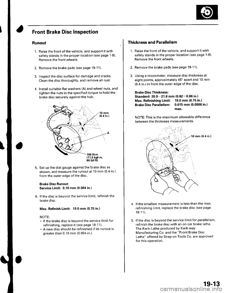
4. lnstall suita ble flat washers (A) andwheel nuts,and
tighten the nuts to the specified torque to hold the
brake disc securely against the hub.
Set up the dial gauge against the brake disc as
shown, and measure the runout at 10 mm (0 4 in.)
from the outer edge of the disc.
Brake Disc Runout:
Service Limit: 0.10 mm (0.00tt in.l
lf the disc is beyond the service limit, refinish the
brake disc.
Max. Retinish Limit: 19.0 mm (0.75 in.)
NOTE:. lf the brakedisc is beyondtheservice limitfor
refinishing, replace it (see page 18-1 1).
. A new disc should be refinished if its runout is
greater than 0.10 mm (0.004 in.).
Thickness and Parallelism
1. Raise the front of the vehicle, and support it with
safety stands in the proper location (see page 1-8).
Remove the front wheels.
2. Remove the brake pads (see page 19-11).
3. Using a micrometer, measure disc thickness at
eight points, approximately 45" apart and 10 mm
{0.4 in.) in from the outer edge of the disc.
Brake Oisc Thickness:
Standard: 20.9 21.8 mm {0.82-0.86 in.}
Max. Refinishing Limit: 19.0 mm 10.75 in.)
Brake Disc Parallelism: 0.015 mm 10.0(X)6 in.)
max.
NOTE: This is the maximum allowable difference
between the thickness measurements
10 mm lo.it in.l
lf the smallest measurement is less than the max.
refinishing limit, replace the brake disc (see page
18-11).
lf the disc is beyond the service limit for parallelism,
refinish the brake disc with an on-car brake lathe.
The Kwik-Lathe produced by Kwik-way
Manufacturing Co. and the "Front Brake Disc
Lathe" offered by Snap-on Tools Co. are approved
for this operation.
4.
': . --'t-'"'-
t,.
19-13
Page 615 of 1139

Conventional Brake Components
Rear Brake Pads Inspection and Replacement
Frequent inhalation of brake pad dust, regardless ofmaterial composition, could be hazardous to your
hea hh.. Avoid breathing dust particles.. Never use an air hose or brush to clean brake
assemblies, Use an OSHA-approved vacuum
cleaner.
Inspection
'1. Raise the rear of the vehicle, and support jt with
safety stands in the proper location (see page 1-8).Remove the rear wheels,
2. Check the thickness of the inner pad (A) andouterpad (B). Do not include the thickness of the brakepad backing plate.
Brake pad thickness:
Standard: 8.5 9.5 mm {0.33-0.37 in.}
Service limit: 1.6 mm (0.06 in.)
B -::--
lf the brake pad thickness is less than the servicelimit, replace allthe pads as a set.
3.
19-20
Replacement
1. Remove the bolt (A) and brake hose {B} from themounting bracket.
Remove the caliper bolts (C), and remove thecaliper (D) from the caliper bracket.
Remove the pad shims (A) and pads (B).3.
A
t{
\
tIA
A
\
r\
))
\
Page 617 of 1139

Conventional Brake Components
Rear Brake Disc Inspection
Runout
1. Raise the rear of the vehicle, and support it with
safety stands in the proper location (see page 1-8).Remove the rear wheels,
2. Remove the brake pads (see page 19-20).
3. Inspect the disc surface for damage and cracks.
Clean the disc thoroughly, and remove all rust,
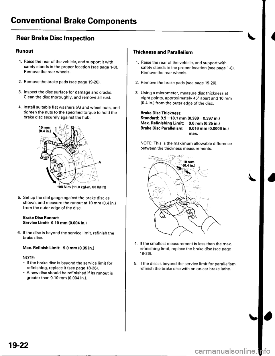
4. lnstall suita ble f lat washers (A) and wheel nuts, andtighten the nuts to the specified torque to hold thebrake disc securely against the hub.
108 N.m (11.0 kgf.m,80lbf.ft)
Set up the dial gauge against the brake disc as
shown. and measure the runout at 10 mm (0.4 in.)
from the outer edge of the disc.
Brake Disc Runout;
Service Limit: 0.10 mm {0.004 in.)
lf the disc is beyond the service limit, refinish thebrake disc.
Max. Refinish Limit: 9.0 mm (0.35 in.)
NOTE:. lf the brake disc is beyondtheservice limitfor
refinishing, replace it (see page 18-26).. A new disc should be refinished if its runout isgreater than 0.10 mm (0.004 in.).
19-22
Thickness and Parallelism
1. Raise the rear of the vehicle, and support with
safety stands in the proper location (see page l-g).Remove the rear wheels.
2. Remove the brake pads {see page 19 20).
3, Using a micrometer, measure disc thickness ateight points, approximately 45'apart and 10 mm
{0.4 in.) from the outer edge of the disc.
Brake Disc Thickness:
Standard: 9.9-10.1 mm (0.389 0.397 in.l
Max. Retinishing Limit: 9.0 mm (0.35 in.)
Brake Disc Parallelism: 0.016 mm 10.0006 in.)
max.
4.lf the smallest measurement is less than the max.
refinishing limit, replace the brake disc (see page
18-26).
lf the disc is beyond the service limit for parallelism,
refinish the brake disc with an on-car brake lathe.
Page 654 of 1139

Body
DoorsComponent Location Index ...........Door Panel Removal/lnstallation .....,..........Door Outer Handle ReplacementDoor Latch ReplacementDoor Glass and RegulatorReplacementDoor Sash Trim Replacement .......................
Door Glass Outer WeatherstripReplacement
Door Weatherstrip Beplacement
Door Glass Adjustment .................................Door Position Adjustment .............................Door Striker Adiustment ................................MirrorsComponent Location Index ...........................Power Mirror Replacement ...........................Mirror Holder Replacement ...........................Rearview Mirror Rep1acement ......................
GlassComponent Location Index ...........................Windshield Replacement
Bear Window Rep1acement ...........................
Ouarter Glass Replacement ..........................MoonroofComponent Location Index ...........................Symptom Troubleshooting Index
Glass Height Adjustment ...............................
Glass ReplacementWind Def lector 8ep1acement ........................Drain Channel Rep1acement ..........................Sunshade Replacement .................................Motor ReplacementFrame and Drain Tube Replacement ............Drain Channel Slider and Cable AssemblyReplacementLimit Switch Adjustment ...............................Closino Force and ODenina Draq Check ......lnterioi TrimComponent Location Index ...........................Trim Removal/lnstallation DoorArea ..........Trim Removal/lnstallation-Rear Side AreaTrim Removal/lnstallation-Cargo Floor AreaTrim Removal/lnstallation-Hatch Area .........Headliner Removal/lnstallation* Carpet Rep1acement .......................................ConsolesConsoles, Front and RearRemova l/lnsta llationFront Console Disassembly/Reassembly .....
20-220,420-620-7
20-920 t0
20- 10
20-1120-1120-1220 13
20-1420-1520-1520-16
20 1120-1920-2520-29
20,3520-3620-3720-3120-3820 3920-4020-4120,42
20 4420-4620,44
20-4920 50
20-51
DashboardInstrument Panel Removal/lnstallation ........Driver's Dashboard Lower CoverRemovat InstallationDriver's Dashboard Under CoverRemova t Insta llation
Oriver's Pocket Removal/lnstallation ............Shift Lever Trim Removal/lnstallation ..........Center Panel Removal/lnstallation ...............Passenger's Dashboard Lower CoverRemova l/lnsta llat ionx Glove Box Removal/lnstallationDashboard Side VentRemoval/lnstallation .................................. 20-64Beverage Holder Removal/lnstallation ........ 20-64Driver'sTray Removal/lnstallation ............... 20-65Passenger's Tray Removal/lnstallation ........ 20 65* Dashboard Removal/lnstallation .................. 20-66Steerinq Hanqer Beam Reolacement ........... 20-68Seats "
Component Location Index ........................... 20-10* Front Seat Removal/lnstallation ................... 20-11* Front Seat Disassembly/Reassembly-Driver's .................................. 20-73* Front Seat Disassembly/Reassembly-Passenger's ........................... 20-74* Front Seat Cover Replacement ..................... 2O-75Rear Seat Removal/1nsta11ation ..................... 20-80Rear Seat-back Latch Replacement .............. 20-81Rear Seat-backStriker Replacement ............ 20-81
20-59
20-59
Rear Seat-back Cover Replacement ............. 20-82Rear Seat Cushion Cover Replacement ....... 20.84BumpersFront Bumper Removal/lnstallation .............Rear Bumoer Removal/lnstallation ...............HoodAdjustmentHood Seal ReplacementHood Insulator Rep1acement .........................Hatch
20-6020,6020 6120-62
20-63
20-63
20,8520-86
20-4720,8820,89
20-5220-5320-5420-55
20-5720-58
Adjustment ................... 20-90Hatch Suppon Strut Replacement ................ 20-91Hatch WeatherstriD Reo1acement ................. 20-92
Fuel Fill DoorAdiustment ................... 20-93Exterior TrimFront Grille Replacement ..............Cowl Covers Replac"rn""t .. . .....................A pillar Corner Trim Replacement ................Roof lMolding Replacement ...........................Rear License Trim ReplacementHatch Spoiler 8ep1acement ...........................Emblem Rep1acement .........................
20-9420-9520-9620-9720,9820-9920-100
Page 689 of 1139

Moonroof
Component Location Index
WIND DEFLECTORReplacement, page 20-38
GLASSHeight Adjustment, page 20 37Replacement, paqe 20-37Closino Force and Ooenino DraoCheck; page 20-48 "
DRAIN CHANNELReplacement, page 20-39
,5
?a<&,
@
..t'- ?.@-@c
_a
@
/,BR^CKEI
COVER
LIMIT SWITCH(AUTO.STOP SWITCH)Adjustment, page 20-46ER
I
CABLE TUBEREAR BRACKETE@
E STOP
.a'
MOONROOFCONTROL UNIT
FRAMEReplacement, page 20-42
CABLE ASSEMBLYBeplacement, page 20-44
*\
)REAR DRAIN VAI-VE
_-""-\q
Replacement, page 20'41
gJ -.- REAR DRA'N TUBE
20-35
Page 690 of 1139

Moonroof
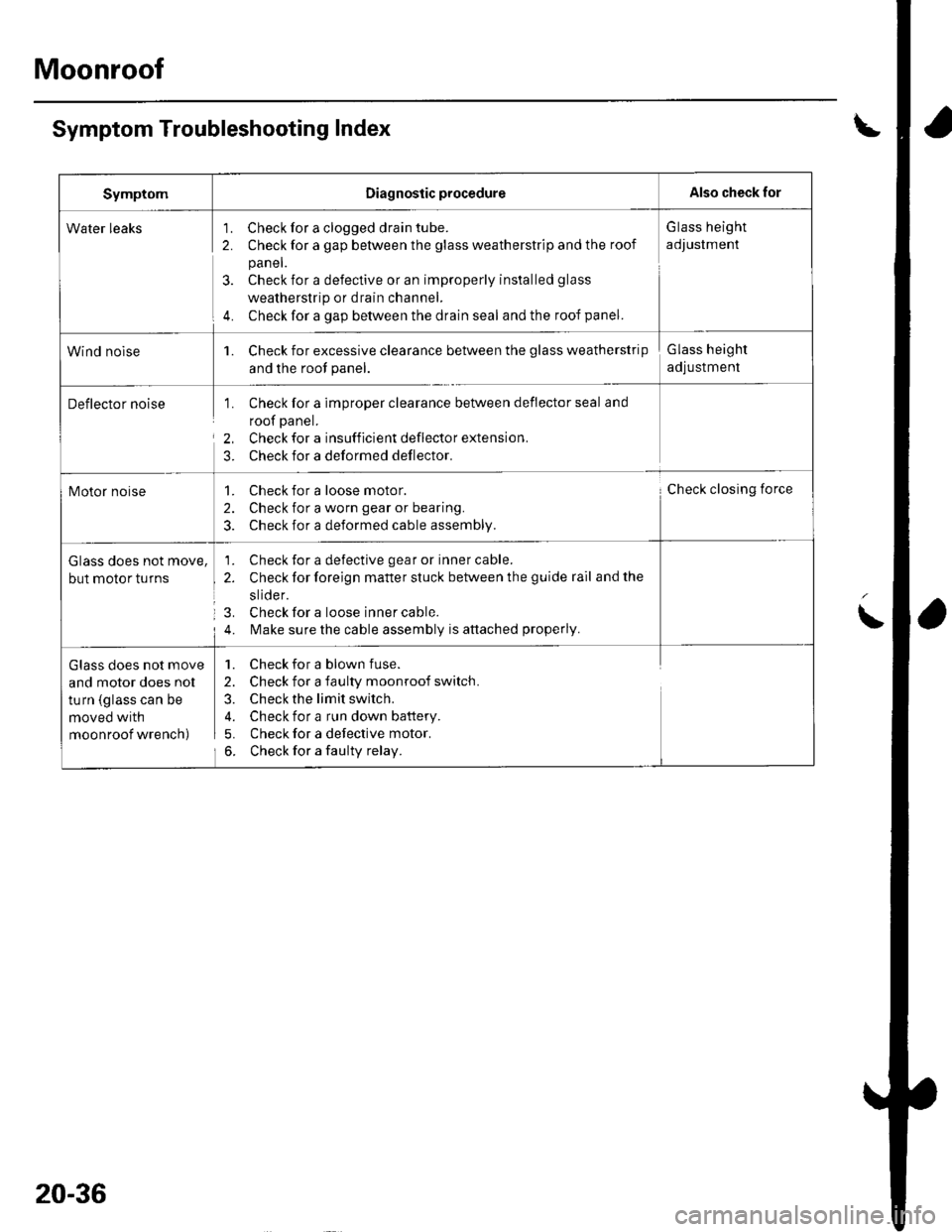
Symptom Troubleshooting Index
SymptomDiagnostic procedureAlso check for
Water leaks'1. Check for a clogged drain tube.
2. Check for a gap between the glass weatherstrip and the roof
panel.
3. Check for a defective or an improperly installed glass
weatherstrip or drain channel.
4. Check for a gap between the drain seal and the roof panel.
G lass height
adJustment
Wind nolse1. Check for excessive clearance between the glass weatherstrip
and the root panel.
Glass height
adjustment
Deflector noise1. Check for a imDrooer clearance between deflector seal and
roof panel.
2, Check for a insufficient deflector extension.
3. Check for a deformed deflector.
Motor noise1. Check for a loose motor.
2. Check for a worn gear or bearing.
3. Check for a deformed cable assembly.
Check closing force
Glass does not move,
but motor turns
1. Check for a defective gear or inner cable.
2. Check for foreign matter stuck between the guide rail and the
slide r.
3. Check for a loose inner cable.
4. l\,4ake sure the cable assembly is attached properly.
Glass does not move
and motor does nol
turn (glass can be
moved with
moonroof wrench)
1. Check for a blown fuse.
2. Check for a faulty moonroof switch.
3. Check the limit switch.
4. Check for a run down battery.
5. Check for a defective motor.
6. Check for a faulty relay.
20-36
Page 700 of 1139

Moonroof
Limit Switch Adjustment
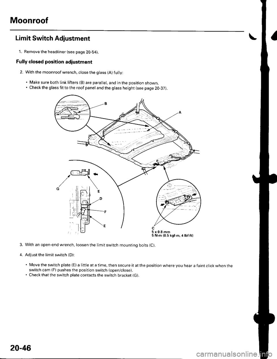
1. Remove the headliner (see page 20-54).
Fully closed position adiustment
2. With the moonroof wrench, close the glass (A) fully:
. Make sure both link lifters (B) are parallel, and in the position shown.. Check the g lass fit to the roof panel and the glass height (see page 20-37).
5x0.8mm5 N.m {0.5 kgf.m,4lbf.ft)
3. With an open-end wrench, loosen the limit switch mounting bolts (C).
4. Adjust the limit switch (D):
' Move the switch plate (E) a little at a time, then secure it atthe position where you hear a faint click when theswitch cam (F) pushes the position switch (open/close).. Check that the switch plate contacts the switch bracket (G).
20-46
Page 819 of 1139

Heating and Air Gonditioning
1.
Compressor Clutch Check
Check the armature plate for discoloration, peeling,
or other damage. lf there is damage, replace the
clutch set (see page 21-49),
Check the rotor pulley bearing play and drag by
rotating the rotor pulley by hand. Beplace the
clutch set with a new one if it is noisy or has
excessive play/drag (see page 21-49).
Measure the clearance between the rotor pulley (A)
and the armature plate (B) all the way around. lf the
clearance is not within specified limits, remove the
armature plate (see page 21-49) and add or remove
shims as needed to increase or decrease clearance.
Clearance: 0.510.15 mm {0.02010.006 in.)
NOTE: The shims are available in four thicknesses:
0.1 mm.0.2 mm,0.4 mm, and 0.5 mm.
21-48
a
4. Release the field coil con nector f rom the holder,
then disconnect it. Check the thermal protector for
continuity. lf there is no continuity, replace the
thermal protector (see page 21-51).
NOTE: The thermal Drotector will have no
continuity above 252to270"F \122lo 132'C). When
the temperature drops below 241 to 219'F (116 to
104'C), the thermal protector will have continuity.
Check resistance of the field coil. lf resistance is not
within specifications, replace the field coil
(see page 21-49).
Field Coil Resistance: 3.05 3.35ohmsat68"F
t20"c)
,\.