2003 HONDA CIVIC Ignition switch
[x] Cancel search: Ignition switchPage 40 of 1139
Starter Circuit Troubleshooting
NOTE:. Airtemperature must be between 59'and 100'F (15'
and 38'C) during this procedure.
. After this test, or any subsequent repair, reset the
engine controle module (ECM) to clear any diagnostlc
trouble codes (DTCS) {see page 11-4).. The battery must be in good condition and fully
charged.. lf you disconnect the baftery, do the ECM idle learn
procedure (see page 11-139).
Recommended Procedure:. Use a starter system tester.. Connect and operate the equipment in accordance
with the manuf acturer's instructions.
Alternate Procedure
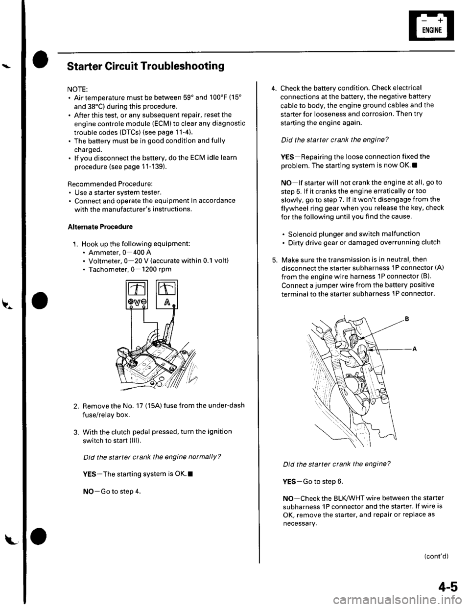
1. Hook up the following equipment:. Ammeter, 0 400 A. Voltmeter, 0 20 V (accurate within 0.1 volt). Tachometer,0 1200 rpm
2.Remove the No. 17 (15A) fuse from the under-dash
fuse/relay box.
With the clutch pedal pressed, turn the ignition
switch to start (lll).
Did the starter crank the engine normally?
YES-The starting system is OK.I
NO-Go to step 4.
3.
L
4-5
4. Check the battery condition. Check electrical
connections at the battery, the negative baftery
cable to body, the engine ground cables and the
starter for looseness and corrosion. Then try
starting the engine again.
Did the statter crank the engine?
YES Repairing the loose connection fixed the
problem. The starting system is now OK.!
NO lf starterwill notcranktheengine atall, goto
step 5. lf it cranks the engine erratically or too
slowly, go to step 7. lf it won't disengage from the
flywheel ring gear when you release the key, check
for the following until you find the cause.
. Solenoid plunger and switch malfunction. Dirty drive gear or damaged overrunning clutch
5. Make sure the transmission is in neutral, then
disconnect the starter subharness 1P connector (A)
from the engine wire harness 'lP connector (B).
Connect a jumper wire from the battery positive
terminal to the starter subharness 'l P connector.
Did the starter crank the engine?
YES-Go to step 6.
NO Check the BLK,ANHT wire between the starter
subharness 1P connector and the starter. lf wire is
OK, remove the starter, and repair or replace as
necessary.
(cont'd)
Page 41 of 1139
Starting System
Starter Circuit Troubleshooting
(cont'dl
6. Check the following items in the order listed untilyou find the open circuit.
. Check the BLIVWHT wire and connectors
between the under-dash fuse/relay box and theignition switch, and between the under-dash
fuse/relay box and the starter.. Check the ignition switch {see page 22-53).. Check the clutch interlock switch and connector.. Check the starter cut relay (see page 22-51).. Check LT GRN wire between the starter cut relayl
under-dash fuse/relay box and the clutch
interlock switch.. Check the BLK wire between the clutch interlock
switch and G501.
7, Check the cranking voltage and current draw.
ls ctanking voltage greatet than or equal to 8.7 V
and current draw less than or equal to 230 A?
YES-Go to step 8.
NO Replace the starter. or remove and
disassemble it, and check these items until you find
the cause.
. Starter armature dragging. Shorted armatu re winding. Excessive drag in engine
8. Check the engine speed while cranking the engine.
ls the engine speed above 100 tpm?
YES Go to step 9.
NO-Replace the starter, or remove and
disassemble it, and check for the following untilyou find the cause.
. Excessively worn starter brushes. Open circuit in commutator brushes. Open circuit in starter armature commutator
segments. Dirty or damaged helical splines or drive gear. Faulty drive gear clutch
9. Remove the starter, and inspect its drive gear andthe flywheel ring gear for damage. Replace anydamaged pans.I
4-6
Clutch Interlock Switch Test
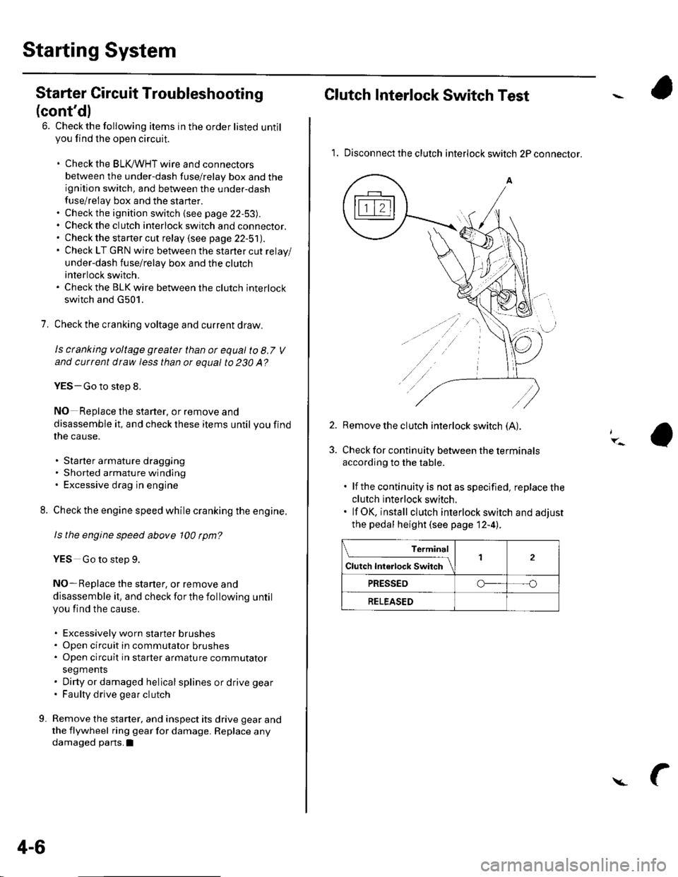
1. Disconnect the clutch interlock switch 2P connector.
2. Remove the clutch interlock switch (A).
Check for continuity between the terminals
according to the table.
. lf the continuity is not as specified, replace the
clutch interlock switch.. lf OK, install clutch interlock switch and adjust
the pedal height (see page 12-4l..
Terminal
Cl","f ri"t.tf ."tS""*Jrl2
PRESSEDo--- --o
RELEASED
Page 52 of 1139
lgnition Timing Inspection
1.
4.
5.
Connect the Honda PGM Tester to the data link
connector (DTC), and check for DTC'S. lf a DTC is
present, diagnose and repair the cause before
inspecting the ignition timing.
Startthe engine. Hold the engine at 3,000 rpm with
no load (in Neutral) until the radiator fan comes on,
then let it idle.
Check the idle speed (see page 11-138).
Follow the tester's prompts in the "SCS" menu
{see the tester operator's manual),
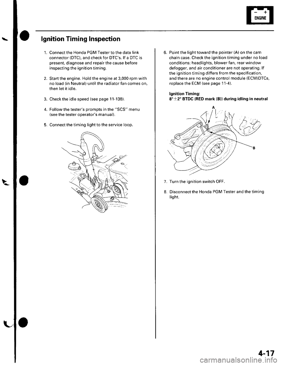
Connect the timing light to the service loop.
o
6. Point the light toward the pointer (A) on the cam
chain case. Check the ignition timing under no load
conditions: headlights, blower fan. rear window
defogger, and air conditioner are not operaling. lf
the ignition timing differs from the specification,
and there are no engine control module {ECM)DTcs,
replace the ECM (see page 11-4)
lgnition Timing:
8"+2" BTDC {RED mark {B)) during idling in neutral
A
7. Turn the ignition switch OFF.
Disconnectthe Honda PGM Tester and thetiming
light.
4-17
Page 57 of 1139
Gharging System
Charging Circuit Troubleshooting
lf the charging system indicator does not come on or
does not go off, or the battery is dead or low, test these
items in the order listed below:
Battery (see page 22-50)
Charging system indicator
Alternator and regulator circuit
Alternator control system
Charging System Indicator Test
1. Turn the ignition switch ON {ll).
Does the chatging system indicator come on?
YES Go to step 2.
NO Go to step 3.
2. Start the engine.
Does the charging system indicator go off?
YES-Charging system indicator circuit is OK. Go
to the Alternator and Regulator circuit Test. t
NO-Go to step 3.
3. Turn the ignition switch OFF.
4. Troubleshoot the multiplex control system (see
page 22 172).
ls the multiplex control system OK?
YES Go to step 5.
NO Check the multiplex control system as
indicated by the diagnostic trouble code (DTC) (see
step 8 on page 22-172).1
5. Disconnect the engine wire harness 6P connector
from the starter sub harness 6P connector.
4-22
\"4
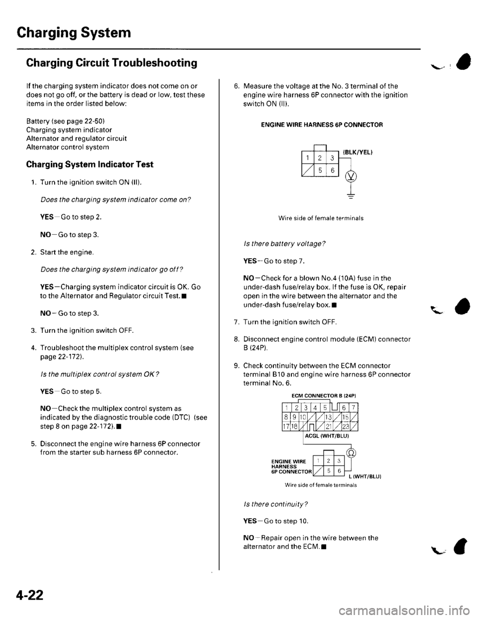
6. Measure the voltage at the No. 3 terminal of the
engine wire harness 6P connector with the ignition
switch ON { ll).
ENGINE WIRE HARNESS 6P CONNECTOR
IBLK/YEL}
Wire side of female terminals
ls there battery voltage?
YES-Go to step 7.
NO-Check for a blown No.4 {10A) fuse in the
under-dash fuse/relay box. lf the fuse is OK, repair
open in the wire between the alternator and the
under-dash fuse/relay box. I
Turn the ignition switch OFF.
Disconnect engine control module (ECM) connector
B (24P).
Check continuity between the ECM connector
terminal B'10 and engine wire harness 6P connector
terminal No. 6.
?
7.
8.
9.
ACGL {WHT/BLU)
ENGINE WIBEHARNESS6PL (WHT/BLUI
Wire side of femaletermina s
ls there continuity?
YES Go to step 10.
NO-Repair open in the wire between the
alternator and the ECN4.I
ECM CONNECTOB A (24P)
Page 59 of 1139
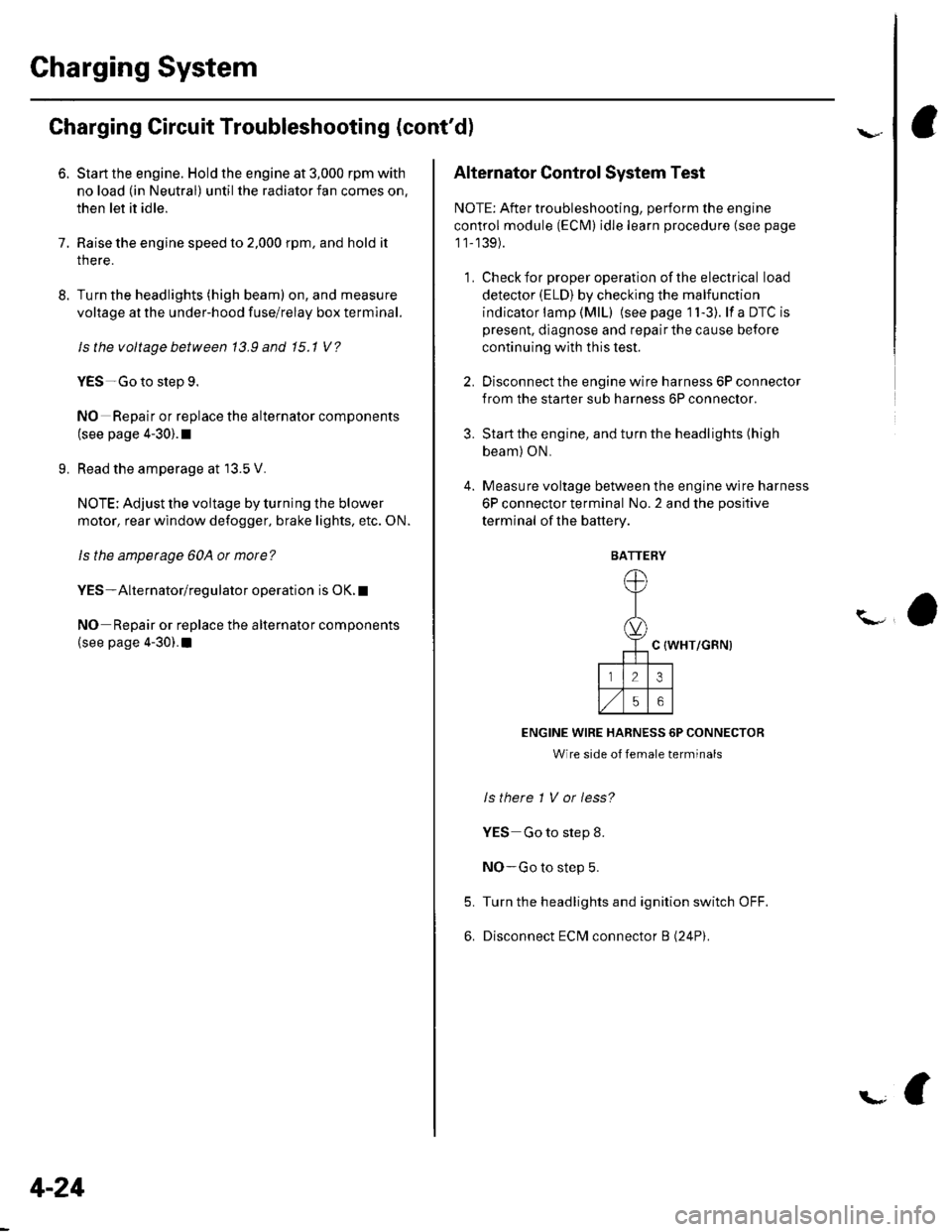
Gharging System
Charging Circuit Troubleshooting (cont'd)
6. Start the engine. Hold the engine at 3,000 rpm with
no load (in Neutral) until the radiator fan comes on,
then let it idle.
7. Raise the engine speed to 2,000 rpm, and hold it
there.
8. Turn the headlights (high beam) on, and measure
voltage at the under-hood fuse/relay box terminal.
ls the voltage between 13.9 and 15.1 v?
YES-Go to step 9.
NO Repair or replace the alternator components
(see page 4-30).1
9. Read the amperage at '13.5 V.
NOTE: Adjust the voltage by turning the blower
motor, rear window defogger, brake lights. etc. ON.
ls the amperage 604 ot morc?
YES-Alternator/regulator operation is OK. I
NO Repair or replace the alternator components(see page 4-30).1
4-24
\,
Alternator Control System Test
NOTE: After troubleshooting, perform the engine
control module (ECM) idle learn procedure (see page
11-139).
1 . Check for proper operation of the electrical load
detector (ELD) by checking the malfunction
indicator lamp (MlL) (see page 1 l-3). lf a DTC is
present, diagnose and repair the cause before
continuing with this test.
2. Disconnect the engine wire harness 6P connector
from the starter sub harness 6P connector.
3. Start the engine, and turn the headlights (high
beam) ON,
4. Measure voltage between the engine wire harness
6P connector terminal No. 2 and the positive
terminal of lhe battery.
C {WHT/GRN)
ENGINE WIRE HARNESS 6P CONNECTOR
Wire side of female terminals
ls there 1 V or less?
YES Go to step 8.
NO-Go to step 5.
Turn the headlights and ignition switch OFF.
Disconnect ECM connector B (24P).
5.
6.
BATTERY
Page 60 of 1139

\
L
7, Check for continuity between ECM connector
terminal 818 and body ground.
ECM CONNECTOR B {24PI
123 t4 t561
8910,/1,/35
11ont,/2123
ACGC {WHT/GRN}
o
Wire side ot female terminals
9.
ls there continuity?
YES-Repair short to ground in the wire between
the alternator and the ECM.I
NO-Check that the terminals are firmly seated at
the ECM connector B. lf OK, substitute a known-
good ECM, and recheck (see page 11-6).
lf prescribed voltage is now available. replace the
original ECM,I
Turn the headlights and ignition switch OFF.
Disconnect ECM connector B (24P).
10. Check for continuity between ECM connector
terminal 818 and engine wire harness 6P connector
terminal No.2.
ACGC (WHT/GRN)
ECM CONNECTOR B l2,lPI
12314l5lll67
8910t.)15
11on2123
oC (WHT/GRN)
23
56
ENGINE WIRE HARNESS 6P CONNECTOR
Wire side oI lemale terminals
ls therc continuity?
YES Repair or replace the starter subharness or
the alternator (see page 4-30).I
NO Repair open in the wire between the
alternator and the ECM.I
4-25
Page 95 of 1139

40. Install the air cleaner housinq.
6x1.0mm12 N m (1.2 kgf.m,8.7 lbt.ft)
Install the air cleaner housing cover (A) and
connect the intake air temperature (lAT) sensor
connector (B),
42. Installthe breather hose (C) and vacuum hose 1D).
41.
43. Installthe intake manifold cover.
6x1.0mm12Nm11.2kgf.m.8.7 tbf.ft)
Installthe battery. Clean the battery posts and
cable terminals with sandpaper, then assemble
them and apply grease to prevent corrosion.
Check that the transmission shifts into gear
smoothly.
Inspect for fuel leaks. Turn the ignition switch ON(ll) {do not operate the starter) so that the fuel pump
runs for about 2 seconds and pressurizes the fuel
line. Repeat this operation two or three times, then
check for fuel leakage at any point in the fuel line.
Refillthe engine with engine oil (see page 8-5).
Refill the transmission with fluid (see page 13-3).
Refill the radiator with engine coolant, and bleed
air from the cooling system with the heater valve
open (see page 10-6).
Perform the engine control module (ECM) idle learnprocedure (see page 11-139).
Inspect the idle speed (see page 1 1-138).
Inspect the ignition timing (see page 4-17).
Check the wheel alignment {see page 18-4).
Enter the anti-theft code for the radio, then enter
the customer's radio station presets.
Set the clock.
YE
44.
41.
]tE
46.
48.
49.
52.
53.
54.
50.
51.
55.
5-15
Page 101 of 1139

Cylinder Head
Engine Compression Inspection
1. Warm up the engine to normal operating
temperature (cooling fan comes on).
2. Turn the ignition switch OFF.
3. Remove the intake manifold cover (see step 1 onpage 6-22).
4, Disconnect all four injector connectors.
5. Start the engine, and let it run until it stalls.
6. Remove the iour ignition coils (see page 4-18).
7. Remove the four spark plugs.
8. Attach the compression gauge to the spark plug
note.
6-6
V,
\
9.
10.
Open the throttle fully, then crank the engine with
the starter motor and measure the compression.
Compression Pressure
Above 930 kpa (9.5 kgf/cm', 135 psi)
Measure the compression on the remaining
cylinders,
Maximum vadation
Within 200 kPa (2.0 kgf/cm', 28 psi)
lf the compression is not within specifications,
check these items, then remeasure the
compressron.
. Damaged orworn valves and seats. Damaged cylinder head gasket. Damaged or worn piston rings. Damaged orworn piston and cylinder bore
11.
\-