2003 HONDA CIVIC under-dash
[x] Cancel search: under-dashPage 1003 of 1139
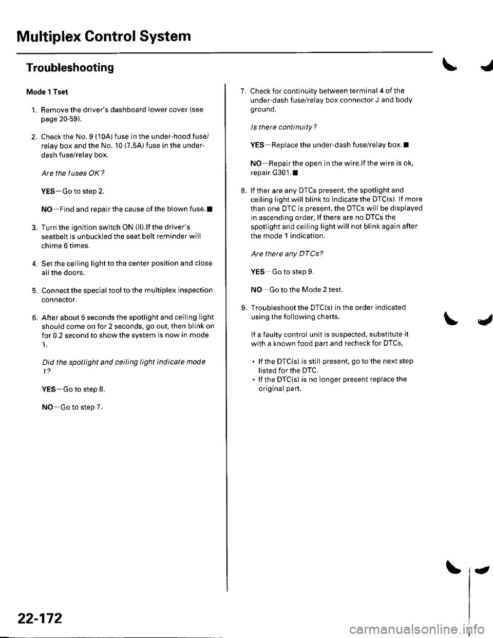
Multiplex Control System
Troubleshooting
Mode 1 Tset
1. Remove the driver's dashboard lower cover {see
page 20-59).
2. Check the No. 9 ( 10A) fuse in the under-hood fuse/
relay box and the No. 10 (7.5A) fuse in the under-
dash fuse/relay box.
Are the fuses OK?
YES-Go to step 2.
NO-Find and repairthe cause ofthe blown fuse.!
3. Turn the ignition switch ON (ll).lf the driver's
seatbelt is unbuckled the seat belt reminder will
chime 6 times.
4. Set the ceiling light to the center position and close
allthe doors.
5. Connect the specialtoolto the multiplex inspection
conneclor.
6. After about 5 seconds the spotlight and ceiling light
should come on for 2 seconds, go out, then blink on
for 0.2 second to show the system is now in mode
1.
Did the spotlight and ceiling light indicate mode
1?
YES-Go to step 8.
NO Go to step 7.
22-172
-
7. Check for continuity between terminal 4ofthe
under-dash fuse/relay box connector J and body
ground.
ls there continuity?
YES Replace the under-dash fuse/relay box.l
NO - Repair the open in the wire.lf the wire is ok,
repair G301.1
8. lf ther are any DTCS present, the spotlight and
ceiling light will blink to indicate the DTC(S). lf more
than one DTC is present, the DTCS will be displayed
in ascending order, lf there are no DTCS the
spotlight and ceiling light will not blink again after
the mode 1 indication.
Are there any DTCg?
YES Go to step 9.
NO Go to the Mode 2 test.
9. Troubleshoot the DTC(S) in the order indicated
using the following charts.
lf a faulty control unit is suspected, substitute it
with a known food part and recheck for DTCS,
. lf the DTC(s) isstill present. go to the next step
listed for the DTC.. lf the DTC(S) is no longer present replace the
original part.
Page 1004 of 1139
I
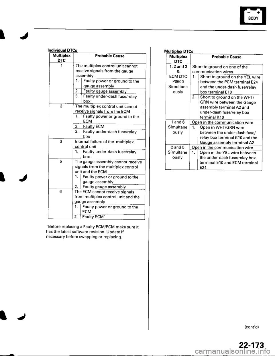
Individual
Multiplex
DTC
Probable Cause
The multiplex control unit cannot
receive signals from the gauge
assemDty.'lFaulty power or ground to thegauge assembly
2.Faulty gauge assemblv
3.Faulty under-dash f use/relay
box
The multiplex control unit cannot
receive signals from the ECM
1Faulty power or ground to the
ECM
2.Faulty ECM?Faulty under-dash fuse/relay
box
JInternal failure of the multiplex
control unit
1Faulty under-dash fuse/relay
box
5The gauge assembly cannot receive
signals from the multiplex control
unit and the ECM
Faulty power or ground to thegauge assembtv
Faulty qauge assemblv
6The ECM cannot receive signals
from multiplex control unit and thegauge assembty
1Faulty power or ground to the
ECM
Faulty ECM'
I
'Before replacing a Faulty ECM/PCM make sure ithas the latest software revision. UDdate if
necessary before swapping or replacing.
DTCs
Multiplex
DTC
Probable Cause
1,2 and 3
&
ECM DTC
P0600
Simultane
ously
Short to ground on one of the
communication wires.
Short to ground on the YEL wire
between the PCM terminal E24
and the under-dash fuse/relay
box terminal E10
2.Short to ground on the WHT/
GRN wire between the Gauge
assembly terminal A2 and
under-dash fuse/relay box
terminal K10
1and6
Simultane
ous ly
Open in the communication wire
IOpen in WHT/GRN wire
between the under-dash fuse/
relay box terminal K10 and the
Gauqe assemblV terminal 42
2and5
Simultane
ously
Open in the communication wire
1Open in the YEL wire between
the under-dash fuse/relay box
terminal E10 and ECM terminal
(cont'd)
22-173
Page 1006 of 1139
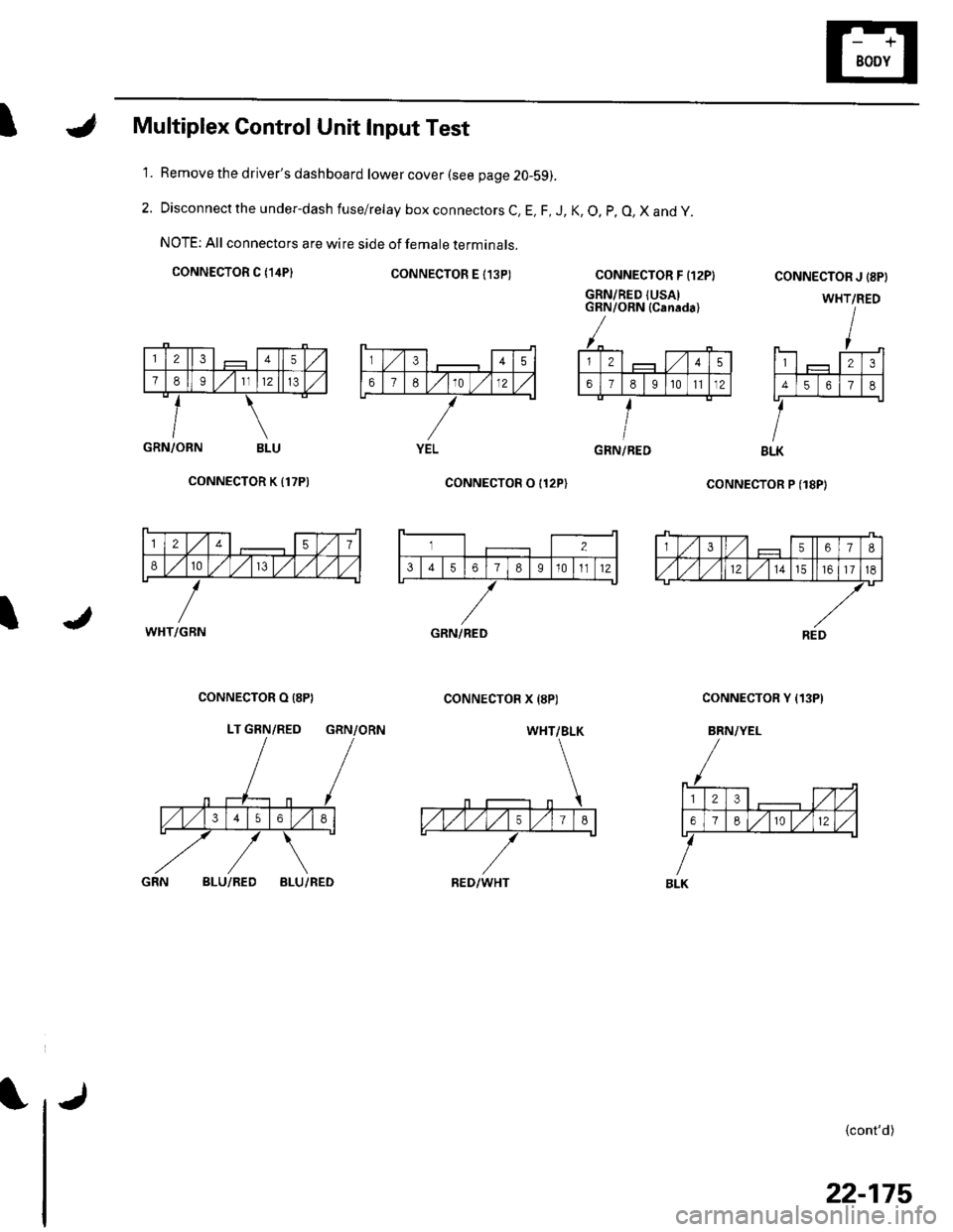
IMultiplex Control Unit Input Test
Remove the driver's dashboard lower cover (see page 20-59).
Disconnect the under-dash fuse/relay box connectors C, E, F, J, K, O, p, O, X and y.
NOTE: All connectors are wire side of female terminals.
CONNECTOR C {14P}CONNECTOR E I13P)
1.
2.
CONNECTOR F {12P}
GRN/RED {USAIGRN/ORN (Canada)
coNNECTOR P (18P)
CONNECTOR J {8PI
WHT/RED
123
4561
BLK
{cont'd)
GRN/ORN BLU
CONNECTOR K {17P)
I
CONNECTOR O I12P)
CONNECTOR X {8P)CONNECTOR O (8P}
LT GRN/RED GRN/ORN
CONNECTOR Y {13P)
BRN/YEL
BLU/REDBLU/RED
345
67E10 )./12
YELGRN/RED
12457
810/V,/ l,/
WHT/GBN
3567I
,/1,/l,/121517
REDGRN/RED
WHT/BLK
RED/WHT
23,/1,/
618r012
BLK
22-175
Page 1080 of 1139
![HONDA CIVIC 2003 7.G Workshop Manual I
g]
3
1 1. Check resistance between the No. 2 terminal of the
floor wire harness 3P connector and body ground.
There should be an open circuit. or at least 1 fvl Q ,
FLOOR WIRE HARNESS 3P CONNECTOR
W HONDA CIVIC 2003 7.G Workshop Manual I
g]
3
1 1. Check resistance between the No. 2 terminal of the
floor wire harness 3P connector and body ground.
There should be an open circuit. or at least 1 fvl Q ,
FLOOR WIRE HARNESS 3P CONNECTOR
W](/manual-img/13/5744/w960_5744-1079.png)
I
g]
3
1 1. Check resistance between the No. 2 terminal of the
floor wire harness 3P connector and body ground.
There should be an open circuit. or at least 1 fvl Q ,
FLOOR WIRE HARNESS 3P CONNECTOR
Wire side ot temale terminals
ls the resistance as specified?
YES-Go to step 12.
NO Short to ground in the floor wire harness or
multiplex control unit. Replace the faulty harness or
part.I
Check resistance between the No. 3 terminal of the
floor wire harness 3P connector and body ground.
There should be an open circuit, or at least 1 M Q.
FLOOR WIRE HARNESS 3P CONNECTOR
LT GRN
Wire side of female terminals
ls the resistance as specified?
YES Go to step 13.
NO-Short to ground in the floor wire
replace the floor wire harness.I
12.
13. Check resistance between the No. 8 terminal of
SRS unit connector C (8P) and the No. 3 terminal of
the floor wire harness 3P connector. There should
be0 1Q.
FLOORWIRE HARNESS SRS UNITCONNECTORC I8P}3P CONNECTOB
Wire side of female terminals
ls the resistance as specitied?
YES Go to step 14.
NO Open in the floor wire harness; replace the
floor wire harness.l
Check resistance between the No. 4 terminal of
SRS unit connector C (8P) and the No. 2 terminal of
the floor wire harness 3P connector. There should
be0-1 0.
14.
FLOOR WIRE HARNESS3P CONNECTORSRS UNIT CONNECTOR C IsPI
Wire side of female terminals
ls the resistance as specified?
YES Replace the SRS unit (see page 23-122).1
NO Open in the floor wire harness or multiplex
control unit, or poor connection at the floor wire
harness, the under-dash fuse/relay box, and the
multiplex control unit. Check the connection at the
floor wire harness, the under-dash fuse/relay box,
and the multiplex control unit. lf the connection is
OK, replace the faulty harness or part.l
harness;
23-73
Page 1103 of 1139
sRs
DTG Troubleshooting (cont'd)
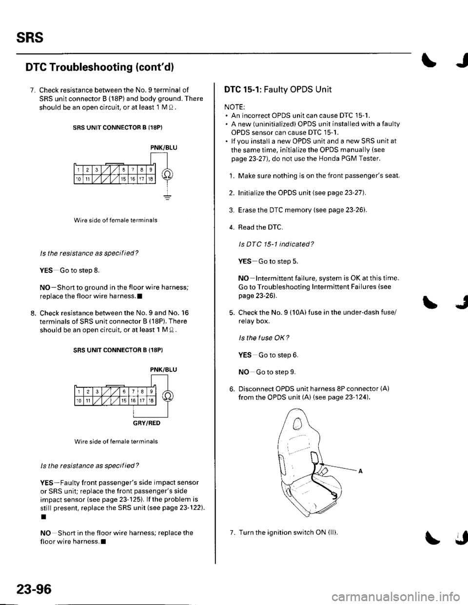
7. Check resistance between the No. 9 terminal of
SRS unit connector B (18P) and body ground. There
should be an ooen circuit, or at least 1 N4 Q.
SRS UNIT CONNECTOR B {18PI
Wire side of female terminals
ls the tesistance as specilied?
YES Go to step 8.
NO-Short to ground in the floor wire harness;
replace the floor wire harness.l
Check resistance between the No.9 and No. 16
terminals of SRS unit connector B (18P). There
should be an open circuit, or at least 1 M O .
SRS UNIT CONNECTOR B (18P)
PNK/BLU
_-r'18 sl /itltlis-l \
236
10tl
GRY/RED
Wire side ot female terminals
ls the resistance as specified?
YES-Faulty front passenger's side impact sensor
or SRS unit; replace the front passenger's side
impact sensor {see page 23-125). lf the problem is
still present, replace the SRS unit (see page 23-122).
I
NO Short in the floor wire harness; replace the
floor wire harness.l
PNK/BLU
23-96
7. Turn the ignition switch ON (ll).
DTC 15-1: Faulty OPDS Unit
NOTE:. An incorrect OPDS unit can cause DTC 15-1.. A new (uninitialized) OPDS unit installed with a faulty
OPDS sensor can cause DTC 15-1.. lf you install a new OPDS unit and a new SRS unit at
the same time, initialize the OPDS manually (see
page 23-27), do not use the Honda PGM Tester.
1. Make sure nothing is on the front passenger's seat.
2. Initialize the OPDS unit (see page 23-27).
3. Erase the DTC memory (see page 23-26]'.
4. Read the DTC.
Is DTC 15-1 indicated?
YES Go to step 5.
NO Intermittent failure, system is OK at this time.
Go to Troubleshooting Intermittent Failures (see
page 23-26).
Check the No. 9 (10A) fuse in the under-dash fuse/
relay Dox,
ls the tuse OK?
YES Go to step 6.
NO Go to step 9.
Disconnect OPDS unit harness 8P connector (A)
from the OPDS unit (A) (see page 23-124).
Page 1104 of 1139
)
)
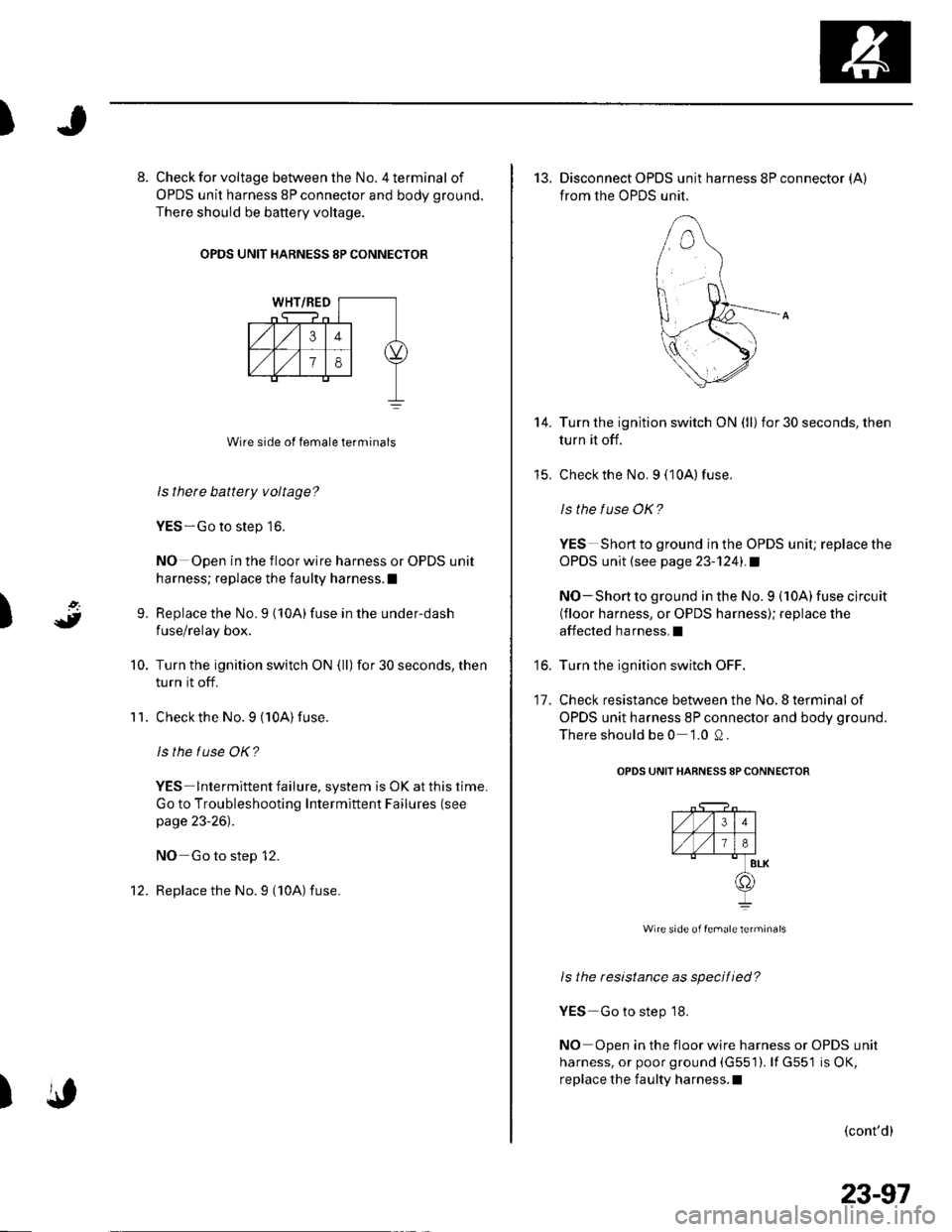
8. Check for voltage between the No. 4 terminal of
OPDS unit harness 8P connector and body ground.
There should be battery voltage.
OPDS UNIT HARNESS 8P CONNECTOR
Wire side of female terminals
ls there battery voltage?
YES-Go to step 16.
NO Open in the floor wire harness or OPDS unit
harness; replace the faulty harness.I
Replace the No.9 (10A)fuse in the under-dash
fuse/relay box.
Turn the ignition switch ON (ll) for 30 seconds, then
turn it off.
Check the No. 9 (10A)fuse.
ls the tuse OK?
YES lntermittent failure, system is OK at this time.
Go to Troubleshooting Intermiftent Failures (see
page 23-26).
NO Go to step 12.
Replace the No. 9 ('l0A) fuse.
9.
10.
11.
)
14.
to.
11.
13. Disconnect OPDS unit harness 8P connector (A)
from the OPDS unit.
Turn the ignition switch ON (ll) for 30 seconds, then
turn it off.
Check the No. 9 (10A) fuse.
ls the f use OK?
YES Short to ground in the OPDS unit; replace the
OPDS unit (see page 23-1241.1
NO-Short to ground in the No. 9 (10A) fuse circuit(floor harness, or OPDS harness); replace the
affected harness.I
Turn the ignition switch OFF.
Check resistance between the No.8 terminal of
OPDS unit harness 8P connector and body ground.
There should be 0 '1.0 Q .
OPDS UNIT HARNESS sPCONNECTOR
l4V-'l^l
TVjEl#BLK
@I
Wire side of female terminals
ls the resistance as specified?
YES Go to step 18.
NO Open in the floor wire harness or OPDS unit
harness, or poor ground (G551). lf G551 is OK,
replace the faulty harness.I
(cont'd)
23-97
Page 1107 of 1139
sRs
DTC Troubleshooting (cont'd)
7. Check the No. 10 (7.5A)fuse in the under-dash
fuse/relay box.
ls the f use OK?
YES Go to step 8.
NO Replace the fuse, then turn the ignition switch
ON (ll). lf the fuse blows again, check for a short in
the No. 10 {7.5A) fuse circuit (ECM wire harness.
floor harness, or OPDS harness).1
8. Disconnect the OPDS unit harness 8P connector (A)
from the OPDS unit (see page 23-124).
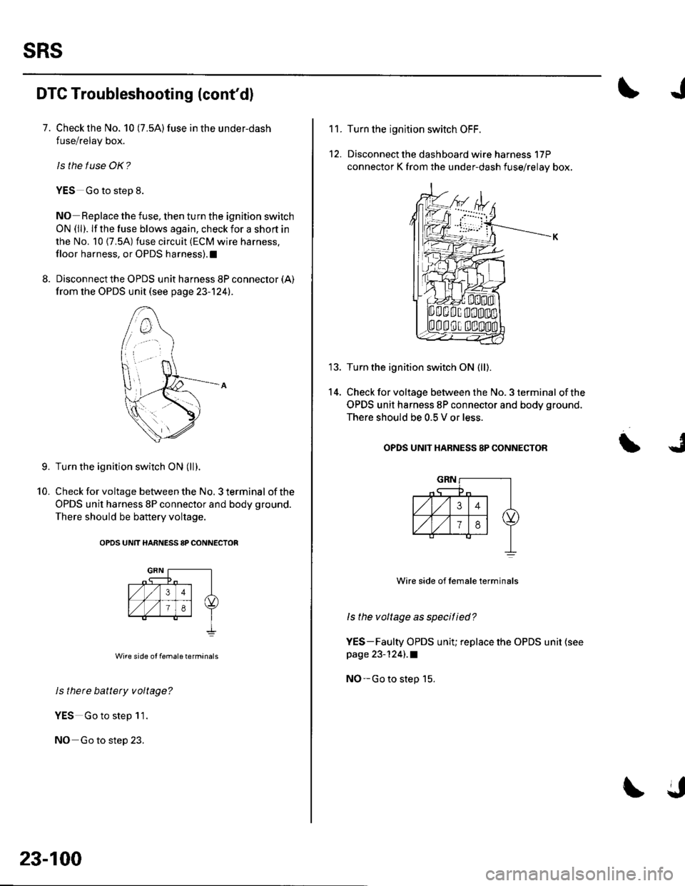
Turn the ignition switch ON (ll).
Check for voltage between the No. 3 terminal of the
OPDS unit harness 8P connector and body ground.
There should be battery voltage.
OPDS UNtT HARNESS 8P CONNECTOR
Wire side of female terminals
ls there battety voltage?
YES Go to step 11.
NO Go to step 23.
9.
10.
23-100
11.
12.
14.
Turn the ignltion switch OFF.
Disconnect the dashboard wire harness 17P
connector K from the under-dash fuse/relay box,
Turn the ignition switch ON (ll).
Check for voltage between the No. 3 terminal of the
OPDS unit harness 8P connector and body ground.
There should be 0.5 V or less.
OPDS UNIT HABNESS 8P CONNECTOR
Wire side of lemale terminals
ls the voltage as specitied?
YES-Faulty OPDS unit; replace the OPDS unit (see
page 23-124) .a
NO-Go to step 15.
Page 1113 of 1139
sRs
6.
SRS Indicator Circuit Troubleshooting (cont'dl
7.
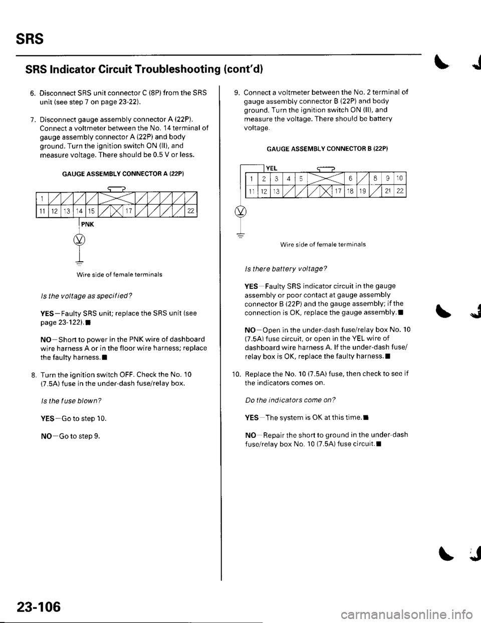
Disconnect SRS unit connector C (8P) from the SRS
unit {see step 7 on page 23-22).
Disconnect gauge assembly connector A (22P).
Connect a voltmeter between the No, l4terminal of
gauge assembly connector A (22P) and body
ground. Turn the ignition switch ON (ll), and
measure voltage. There should be 0.5 V or less.
GAUGE ASSEMBLY CONNECTOR A {22P)
Wire side of female terminals
ls the voltage as specitied?
YES-Faulty SRS unit; replace the SRS unit (see
page 23-'l22l.a
NO-Short to power in the PNK wire of dashboard
wire harness A or in the floor wire harness; replace
the faulty harness.l
L Turn the ignition switch OFF. Check the No. 10
{7.5A)fuse in the under-dash fuse/relay box.
ls the tuse blown?
YES-Go to step 10.
NO Go to step 9.
23-106
J
9. Connect a voltmeter between the No.2 terminal of
gauge assembly connector B (22P) and body
ground. Turn the ignition switch ON (ll), and
measure the voltage. There should be battery
voltaqe.
GAUGE ASSEMBLY CONNECTOR B (22P}
YEL
12345X68910
ll12,/ ,/,/x11o2122
Wire side of female terminals
ls therc battery voltage?
YES Faulty SRS indicator circuit in the gauge
assembly or poor contact at gauge assembly
connector B (22P) and the gauge assembly; if the
connection is OK, replace the gauge assembly.l
NO Open in the under-dash fuse/relay box No. 10
(7.5A) fuse circuit, or open in the YEL wire of
dashboard wire harness A. lf the under-dash fuse/
relay box is OK, replace lhe faulty harness.l
Replace the No. 10 (7.5A) fuse, then check to see if
the indicators comes on.
Do the indicators come on?
YES The system is OK at thls time.l
NO Repair the short to ground in the under-dash
fuse/relay box No. 10 (7.5A)fuse circuit.l
10.