Page 85 of 1139
18.
19.
Remove the drive belt (see page 4-26).
Remove the lvC line mounting bolt.
20. Remove the radiator cap.
21. Raise the hoist to full height.
22. Remove the front tires/wheels.
23. Remove the splash shield.
o@
24. Loosen the drain plug in the radiatorto drain the
engine coolant (see page 10-6).
25. Drain the transmission fluid (see page 13'3).
26. Drain the engine oil {see page 8-5).
27. Disconnect the stabilizer links (see page 18-18).
28. Disconnect the suspension lower arm ball joints
(see step 3 on page 18-19).
29. Remove the driveshafts {see page 16-3). Coat all
precision finished surfaces with clean engine oil.
Tie plastic bags over the driveshaft ends.
30. Disconnect the air fuel ratio {4,/F) sensor connector
(A) and secondary heated oxygen sensor
(secondary HO2S) connector (B), then remove the
three way catalytic converter {TWC) assembly {C).
31. Remove the lower hose.
(cont'd)
5-5
Page 118 of 1139

Gylinder Head Removal
NOTE:. Use fender covers to avoid damaging painted
surfaces.
To avoid damage, unplug the wiring connectors
carefully whlle holding the connector portion.
To avoid damaging the cylinder head, wait until the
engine coolant temperature drops below 100'F (38"C)
betore loosening the cylinder head bolts.
Mark all wiring and hoses to avoid misconnection.
Also, be sure that they do not contact other wiring or
hoses, or interfere with other parts.
'1.
2.
3.
Drain the engine coolant (see page 10-6).
Remove the drive belt (see page 4-26).
Remove the intake manifold {see page 9-3).
Remove the air cleaner housing (see step 7 on page
5-2t.
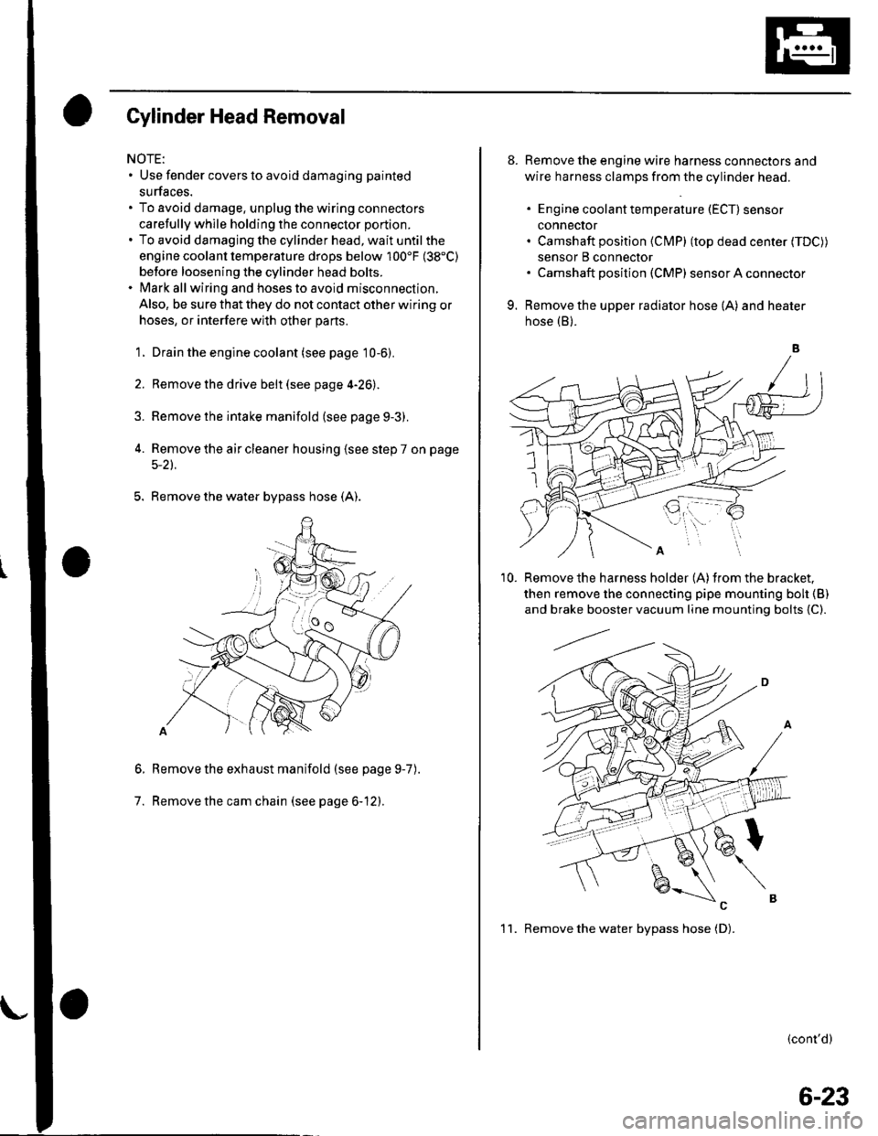
5. Remove the water bypass hose (A).
Remove the exhaust manifold (see page 9-7
Remove the cam chain (see page 6-12).
6.
7.
).
8. Remove the engine wire harness connectors and
wire harness clamps from the cylinder head.
. Engine coolant temperature (ECT) sensor
conneclor. Camshaft position (Cl\4P) (top dead center (TDC))
sensor B connector. Camshaft posilion (CMP) sensor A connector
9. Remove the upper radiator hose (A) and heater
hose (B).
'10. Remove the harness holder (A)from the bracket,
then remove the connecting pipe mounting boh {B)
and brake booster vacuum line mounting bolts {C).
(cont'd)
1 1. Remove the water bvpass hose (D).
6-23
Page 149 of 1139
1.
OilPan Removal
Drain the engine oil (see page 8-5).
lf the engine is still in the vehicle, remove the
subframe.
-1 Attach the chain hoist to the engine (see step
35 on page 5-6).-2 Disconnectthe suspension lower arm balljoints (see step 3 on page 18-19).-3 Remove the rear mounl mounting bolts (see
step 39 on page 5-7).-4 Remove the front mount mounting bolt (see
step 40 on page 5-7).-5 Use a marker to make alignment marks on the
reference lines that align with the centers of
the rear subframe mounting bolts. Remove the
front subframe (see step 43 on page 5-8).
Remove the bolts/nuts securing the oil pan.
Drive an oil pan seal cutter between the oil pan and
cylinder block.
5. Cut the oil panseal bystrikingthesideofthecutter
to slide the cutter along the oil pan.
6. Remove the oil pan.
7-11
Page 169 of 1139
Component Location Index
OIL PUMPCHAIN TENSIONER
DRAIN BOLT
OIL PANRemoval, page 7 11Installataon, page 7-27
OIL PUMPOverhaLrl, page 8-8
HL]
BAFFLE PLATE
OIL FILTER FEED PIPEReplacement, page 8-7
OIL FILTERReplacement, page 8-6
OIL CONTROLORIFICE
WASHER
OIL PRESSURE SWITCHSwitch Test, page 8 4Oil Pressure test, page 8'4Replacement, page 8 16
-&\JrI
--t N\ksrarr lN-?cKEr dczt$)
#1
\OIL PUMPCHAIN GUIDE
8-3
Page 171 of 1139
Engine Oil Replacement
Warm up the engine.
Remove the drain bolt (A), and drain the engine oil.
nA
44 N.m {i1.5 kgf.m,33 lbf.ft)Do not overtighten.
Reinstall the drain bolt with a new washer (B).
Refillwith the recommended oil (see page 3-2).
Capacity
4.0 0 (4.2 US qt) at oilchange.
4.2 014.4 US qt) at oilchange including filter.
5.3 015.6 US $) after engine overhaul.
Run the engine for more than 3 minutes. then check
for oil leakage.
1.
2.
3.
5.
8-5
Page 195 of 1139
1.
2.
Water Pump Inspection
Remove the drive belt (see page 4-26),
Turn the water pump pulley counterclockwise.
Check that it turns freely.
Check for signs of seal leakage. A small amount of"weeping" from the bleed holes (A) is normal.
Water Pump Replacement
1. Remove the drive belt (see page 4-26).
2. Drain the engine coolant {see page 10-6).
3. Remove the crankshaft pulley (see page 6-11).
4. Remove the six bolts securing the water pump,
then remove the water pump (A).
6x1.0mm12 N m {1.2 kgt m,8.7 rbf.ft)
Inspect and clean the O-ring groove and mating
surface with the water passage.
Installthe water pump with new O rings in the
reverse order of removal.
7. Clean up any spilled engine coolant.
8. Installthe crankshaft pulley (see page 6-12).
L Refill the radiator with engine coolant, and bleed
air from the cooling system with the heater valve
open {see page 10-6}.
10-5
Page 196 of 1139
Cooling System
1 . Look at the coolant level in the reserve tank. Make
sure it is between the MAX mark (A) and MIN mark(B),
Goolant Check
lf the coolant level in the reserve tank is at or below
the MIN mark, add coolant to bring it up to the l\4AX
mark, and inspect the cooling system for leaks.
10-6
\-
Coolant Replacement
1.
\
Start the engine. Set the heater temperature control
dial to maximum heat. then turn off the ignition
switch. Make sure the engine and radiator are cool
to the touch.
Remove the radiator cap.
Remove the splash shield (see step 23 on page 5-5).
Loosen the drain plug (A), and drain the coolant.
Remove the reserve tank drain cap (A), and drain
the coolant.
\
Page 197 of 1139

1.
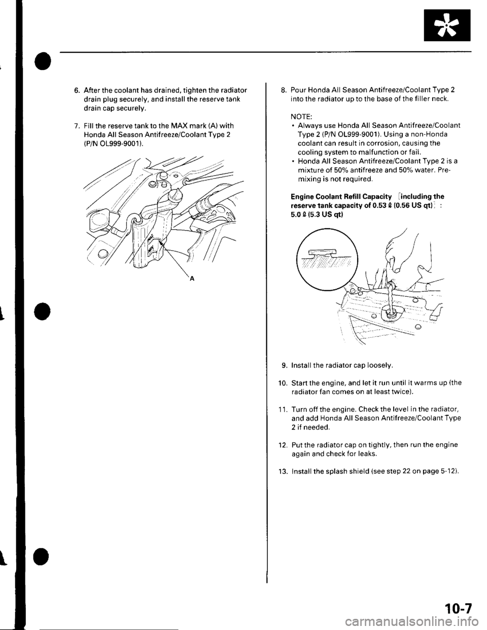
After the coolant has drained, tighten the radiator
drain plug securely. and installthe reserve tank
drain cap securely.
Fill the reserve tank to the MAX mark (A) with
Honda All Season Antifreeze/Coolant Tvpe 2
(P/N O1999-9001).
8. Pour Honda All Season Antifreeze/Coolant Type 2
into the radiator up to the base of the filler neck.
NOTE:. Always use Honda All Season Antifreeze/Coolant
Type 2 {P/N 01999-9001). Using a non-Honda
coolant can result in corrosion, causing the
cooling system to malfunction or fail.. Honda All Season Antifreeze/Coolant Type 2 is a
mixture of 50% antifreeze and 507o water. Pre-
mixing is not required.
Engine Coolant Refill Capacity including the
reserve tank capacity of 0.53 4 (0.56 US gtl :
5.0 0 (s.3 US qt)
Installthe radiator cap loosely.
Start the engine, and let it run until it warms up (the
radiator fan comes on at least twice).
Turn off the engine. Check the level in the radiator,
and add Honda All Season Antifreeze/Coolant Type
2 if needed.
Put the radiator cap on tightly, then run the engine
again and check for leaks.
lnstall the splash shield (see step 22 on page 5-12).
10.
11.
L
tJ.
10-7