2003 HONDA CIVIC power steering
[x] Cancel search: power steeringPage 24 of 1139

cont'
ItemMeasuremeniOualificationSpecilicationSTEERINGTypeElectric, Power assisted rack and pinion
Overall ratio15.1Turns,lock to-lock
Steering wheel diameter360 mm (14.2 in)SUSPENSIONTypeIndependent srrul with stabiliTer. coil springRearDouble wishboneShock absorberFrontTelescopic, hydraulic. nitrogen gas-frlled
RearTelescopic, hydraulic, nitrogen gas,filledWHEEL
ALIGNMENT
CamberFront0"00'
Bear0.45'�
CasterFront1'33'�TotaltoeFront0 mm (0 in.)
RearIn 2 mm (1/16 in.)BRAKESType of service brakeFrontPowerassisted self-adjusling ventilated disc
BearPower-assisted self-adjusting solid discType of parking brakeMechanical actuating, rear wheelsPad friction surface areaFront45 cm'(7.0 sq in.)x2
Rear28 cm'(4.3 sq in.) x 2TIRESSize offront and reartiresPl95/60 815 88VSize o{ spare tireT125r0 D15 95MAIR
CONDITIONING
CompressorTypeScroll
Number of
cylinders
Capacity85.7 m015.23 cu in.)/rev.
Maximum speed12,000 rpm
Lubricant capacity130 m0 {4 1/3 floz)
LubricanttypeSP-10 (P/N 38897'P13-A01AH or38899-P13 A01)CondenserTypeCorrugated finEvaporatorTvpeCorrugated fin
BlowerTypeSirocco fan
Motor type220 Wl12 V
Speed control4 Speeo
Maximum capacity480 m" 116.900 cu ft)/hTemperature controlAirmixtype
Compressor clutchTvpeDry, single plate, poly-V belt drive
Electricalpower
cons!mptron at
68"F (20.C)
42 W maximum at 12 V
RefrigerantTypeHFC 134a (R-134a)
Capacity500 550 g (17.6 19.4 oz)
Design Specifications
C
aL
2-12
../ a
Page 33 of 1139

L
A
I
Do the items in parts A, B, C, D, E, F, and G as required for mileage/time interval listed.
Feplace engine oil(see pageS 5). Capacity withoutlilter change:4.0 q (4.2 US qt,3.5lmp qt)
Replace engjne oil filter (see page I 6). Capacity with filter change: 4.2 0 14.4 US qt, 3.7 lmp qt)Insoect front and rear brakes,. Check pads and discsforwearlthickness), damage, andcracks.. Check calipers for damage, leaks, and tightness of mount bolts.Lubricate door locks, latches and hinges with Honda white lithium grease.Rotate tires, if the vehicle has been driven the distance listed. Follow the pattern shown in the Owner's Manual-Check tire inflaron aoocondition,Inspecttie rod ends, steering gearbox, and boots (see page 17,5).. Check rack grease and steering linkage.. Check boots for damage and leaking grease.. Checklluid linefordamage and leaks.Inspect suspensron components. Check bolts for tightness.. Check condition of ball joint boots for deterioration and damage.Inspect driveshaft boots. Check boots for cracks and boot bands for tightness (see page 16-3).
Check parking brake adjustment. Should be fully applied within 7 to 9 clicks.Insp€ct brake hoses and lioes. (including ABS). Check the master cylinder, proportioning control valve, and ABS modulator for damageand leakage (see page 19-24).Check all fluid levels and condition ot lluids; check for leaks. lf necessary, add MTF (see page 13 3), engine coolant, brake fluid, andwindshield washer f luid.Inspect exhaust system*. Check catalytic converter heat shield, exhaust pipe and muffler for damage, leaks, and tightness (see page 9 8).Inspect fuel lines and connections*. Check for loose connections, cracks and deterioration; retighten loose connections and replacedamaged pans (seo page 11'146).Check alllights. Checkfunction otallinterior and exterior lights, andthe position ofthe headlights (see page 22-68).Inspect the v€hicle underbody. Check the paint for damage, scratches, stone chippin0, and dents.
L
D
E
F
H
InsDect and adiust drive belt.. Look tor cracks and damage, and inspect auto tensioner {needs no adjustment).Reolace dust and oollen filter.
Replace air cleaner element every 15,000 miles 124,000 km) in dustv condition {independent ol timei otherwise use Normal Conditionsscredule (see page 11-162).
lReplaceaircleanerelementevery30,000miles(48,000km)(independento{timei(seepagell-162).
Replace brake fluid every 3 years (independent oJ mileagei.
Replacethe dust and pollen Iilter every 15,000 miles ifvehicle is driven mostlywhere air has high concentration olsootfrom industryanddiesel powered vehiclesj also replace the dust and pollen filter anytime aarflow is less than ussal (see pags 21-39).
According to state and federal regulations, failure to do the maintenance items marked with asterisk (*) will not void customer's emissionswarranties. However, Honda recommends that all maintenance services be done at the recommended interval to ensure long-term reliability,
3-7
Page 229 of 1139
![HONDA CIVIC 2003 7.G Workshop Manual Fuel and Emissions Systems
System Descriptions (contdl
ECM lnputs and Outputs at Connector E (31P}
L
u
1iMoFPR
2sr-{]zs3LG34SG3
6$1025HTC
1M RLY
8AFSHTCR
I
14FTP15ELD
16EPSLD
18ACC20Z/VBS21VSV
22BKSW HONDA CIVIC 2003 7.G Workshop Manual Fuel and Emissions Systems
System Descriptions (contdl
ECM lnputs and Outputs at Connector E (31P}
L
u
1iMoFPR
2sr-{]zs3LG34SG3
6$1025HTC
1M RLY
8AFSHTCR
I
14FTP15ELD
16EPSLD
18ACC20Z/VBS21VSV
22BKSW](/manual-img/13/5744/w960_5744-228.png)
Fuel and Emissions Systems
System Descriptions (cont'dl
ECM lnputs and Outputs at Connector E (31P}
L
u
1iMoFPR
2sr-{]zs3LG34SG3
6$1025HTC
1M RLY
8AFSHTCR
I
14FTP15ELD
16EPSLD
18ACC20Z/VBS21VSV
22BKSW23K-LINE24SEFMJ26NEP
21rMoCD
29scs30WEN31MIL
Wire side of female terminals
NOTE: Standard battery voltage is '12 V.
TerminalnumberWire colorferminal nameDescription Signal
GRNI/ELIMO FPR (IMMOBILIZERFLJEL PUMP RELAYIDrives PGM Fl main relay 20Vfor2 seconds after turning ignition switch ON{ll). then batterv voltaoe2WHT/REDSHO2S (SECONDARYHEATED OXYGEN SENSOR(SECONDARY HO2S),SENSOR 2r
Detects secondary HO2S{sensor 2) signalWith throttle Jully opened from idle with fullywarmed up engine: above 0.6VWith throttle quickly closed: below 0.4 V
3BRN/YELLG3 (LOGIC GROUND)cround forthe ECM/PCMcontrolcircuitLess than 1.0 V at all times
4PNKSG3 {SENSOR GBOUND)Sensor oroundLess than 1.0 V at all times5YEUELUVCC3 {SENSOR VOLTAGE)Provides sensor voltageWith ignition switch ON (ll): about 5 VWith ionition switch OFF: about 0 V6BLKATr'HTSO25HTC (SECONDARYHEATED OXYGEN SENSOR(SECONDARY H02S)HEATER CONTROL)
Drives secondary HO2SheaterWith ignition switch ON (ll): baftery voltageWilh fullv warmed up engine running: dul,controlled
1REDA/ELMRLY (PGM.FI MAINRELAY}Drives PGM-Flmain relay 1Power source forthe DTCWith ignition switch ON (ll): about 0 VWith ignition switch OFF: battery voltage
IORNAFSHTCR {AIR FUEL BATIO(Iy'F)SENSOR HEATERCONTROL RELAY)
Drives air fuel ratio sensorheater relayWith ignition swirch ON {ll): 0 V
IYEUBLKIGl (IGNITION SIGNAL)Detecrs ignition signalWith ignition switch ON (ll): battery voltageWith iqnition switch OFF: about 0 V't4LT GRNFIP lFUEL TANKPRESSURE (FTP) SENSOR)Detects FTP sensor signalWith ignition switch ON (ll) and fuel fill cap open:about 2.5 VGRN/REDELD (ELECTRICAL LOADDETECTOF)Detects ELD signalWith ignition swjtch ON itt):aOoutO.t V l-gV(deDendino on electrical load)LT GRN/8LKEPSLD (ELECIRICALPOWEB STEEBING LOADDETECT)
Detects Power steering loadsrgnalAt idle with steering wheel in straight aheadposition: about 0 VAt idle with steering wheelatfull lock: momentary
'18REDACC (Ay'C CLUTCH RELAY)Drives P,/C clutch relayWith compressor ON: about 0 VWith comoressor OFF: batterv voltaoe
11-22
\-
Page 239 of 1139

Fuel and Emissions Systems
(
{
System Descriptions (cont'd)
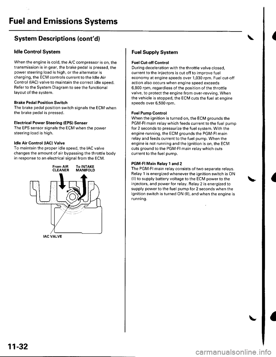
ldle Control System
When the engine is cold, the Ay'C compressor is on, the
transmission is in gear, the brake pedal is pressed. thepower steering load is high, or the alternator is
charging, the ECIM controls current to the ldle Air
Control (lAC) valve to maintain the correct idle speed.
Refer to the System Diagram to see the functional
layout of the system.
Brake Pedal Position Switch
The brake pedal position switch signals the ECM when
the brake pedal is oressed.
Electrical Power Steering (EPS) Senser
The EPS sensor signals the ECM when the power
steering load is high.
ldle Air Control llACl Valve
To maintain the proper idle speed, the IAC valve
changes the amount of air bypassing the throttle body
in response to an electrical signal from the ECM.
From AIR To INTAKECLEANER MANIFOLD
IAC VALVE
11-32
Fuel Supply System
Fuel Cut-off Control
During deceleration with the throttle valve closed,
current to the injectors is cut off to improve fuel
economy at engine speeds over 1,030 rpm. Fuel cut-off
action also occurs when engine speed exceeds
6,900 rpm, regardless of the position of the throttle
valve, to protect the engine from over-rewing. When
the vehicle is stopped. the ECM cuts the fuel at engine
speeds over 6,500 rpm.
Fuel Pump Control
When the ignition is turned on, the ECM grounds the
PGM-Fl main relay which feeds current to the fuel pump
for 2 seconds to pressurize the fuel system, With the
engine running. the ECM grounds the PGM-Fl main
relay and feeds current to the fuel pump. When the
engine is not running and the ignition is on, the ECI\4
cuts ground to the PGM-Fl main relay which cuts
current to the fuel pump.
PGM-FI Main Relay 1 and 2
The PGM-Fl main relay consists of two separate relays.
Relay 1 is energized whenever the ignition switch is ON(ll) to supply battery voltage to the ECM power to the
injectors, and power for relay, Relay 2 is energized to
supply power to the fuel pump for 2 seconds when the
ignition switch is turned ON (ll), and when the engine is
runnrng.
Page 342 of 1139

15. Check for continuity between body ground and
ECIM connector terminal 813.
ECM CONNECTOR B I24P}
Wire side of female terminals
ls there continuity?
YES Repair short in the wire between the ECM
(813) and the alternator.l
NO Update the ECM if it does not have the latest
software, or substitute a known-good ECM, then
recheck lsee page 1 1-6). lf the symptom/indication
goes away with a known-good ECM, replace the
original ECM.I
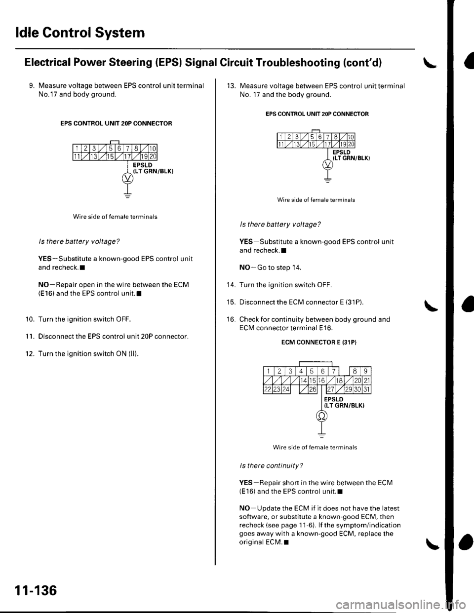
Electrical Power Steering (EPSI
Signal Circuit Troubleshooting
Turn the ignition switch ON (ll).
l\4easure voltage between ECM connector
terminals 424 and E16.
1.
2.
3.
4.
5.
Wire side of female terminals
ls there battery voltage?
YES Go to step 6.
NO Go to step 3.
Start the engine.
Turn the steering wheel lo the full lock position.
l\4easure voltage between ECM connector
terminals A24 and E16.
ls there momentaty battery voltage?
YES The EPS signal is OK.t
NO Go to step 10.
6. Turn the ignition switch OFF.
7. Disconnect the EPS control unit 20P connector.
8. Turn the ignition switch ON (ll).
(cont'd)
11-135
Page 343 of 1139

ldle Control System
Electrical Power Steering (EPSI Signal Circuit Troubleshooting (cont'd)
9. Measure voltage between EPS control unitterminal
No.l7 and body ground.
EPS CONTROL UNIT 2OP CONNECTOR
Wire side of female terminals
ls there battety voltage?
YES-Substitute a known-good EPS control unit
and recheck.I
NO- Repair open in the wire between the ECM(E 16) and the EPS control unit.l
Turn the ignition switch OFF.
Disconnect the EPS control unit 20P connector.
Turn the ignition switch ON (ll).
10.
I '�I.
12.
11-136
'13. l\4easure voltage between EPS control unitterminal
No. 17 and the body ground.
EPS CONTROL UNIT 2OP CONNECTOR
Wire side of female terminals
ls there battery voltage?
YES Substitute a known-good EPS control unit
and recheck.l
NO-Go to step 14,
Turn the ignition switch OFF.
Disconnectthe ECM connector E {31P).
Check for continuity between body ground and
ECI\4 connector terminal E16.
ECM CONNECTOR E {31PI
14.
t5_
16.
12345617l 189
56./182A21
2223zi ./29 30ol
EPSLD{LT GRN/BLK)
a,
Wire side ot Iemale terminals
lsthere continuity?
YES Repair short in the wire between the ECN4(E 16) and the EPS control unit.l
NO Update the ECM if it does not have the latest
software, or substitute a known-good ECM, then
recheck (see page 11-6). lf the symptom/indicationgoes away with a known-good ECM, replace the
original ECM.I
Page 493 of 1139

Steering
Steering
Special Tools ............. 17-2
Comoonent Location Index ......................................... 17-3
Steering Wheel Rotational Play Check .....................". 17-4
Power Assist Check .................. .......... 17-4
Steering Linkage and Gearbox Inspection ................. 17-5
Steering Wheel Removal .........................,................... 17-6
Steering Wheel Disassembly/Reassembly ................ 17-7
Steering Wheel Installation ............... 17-8
Steering Column Removal and Installation ...........'... 17-9
Steering Column Inspection .............. 17-11
Steering Lock Replacement .......................................'. 17-'12
Rack Guide Adiustment ....."........'..'.. 17-13
Electrical Power Steering (EPS)17-15
Page 496 of 1139

Steering
Steering Wheel Rotational Play
Check
1. Turn the front wheels to the straight ahead position.
2. Measure how far you can turn the steering wheel
left and right without moving the front wheels.
. lf the play is within the limit, the gearbox and
linkage are OK.. lf the playexceedsthe limit, adjustthe rack guide
{see page '17-13). lf the play is still excessive after
rack guide adjustment, inspect the steering
linkage and gearbox {see page 17-5).
BOTATIONAL PLAY: 0 10 mm (0-0.39 in.l
+:
17-4
Power Assist Check
Start the engine, and let it idle.
Attach a commercially available spring scale to the
steering wheel. With the engine idling and the
vehicle on a clean, dry floor, pull the scale as
shown, and read it as soon as the tires begin to turn.
\
1.
3. lf the scale reads no morethan 29 N (3.0 kgf,6.6 lbf),
the power assist is OK. lf it reads more, check these
items:
. Front tire pressure. Steering linkage (see page 17-5). Rack gulde adjustment (see page 17-13). EPS system (see page 17-18)