2003 HONDA CIVIC belt
[x] Cancel search: beltPage 1003 of 1139
Multiplex Control System
Troubleshooting
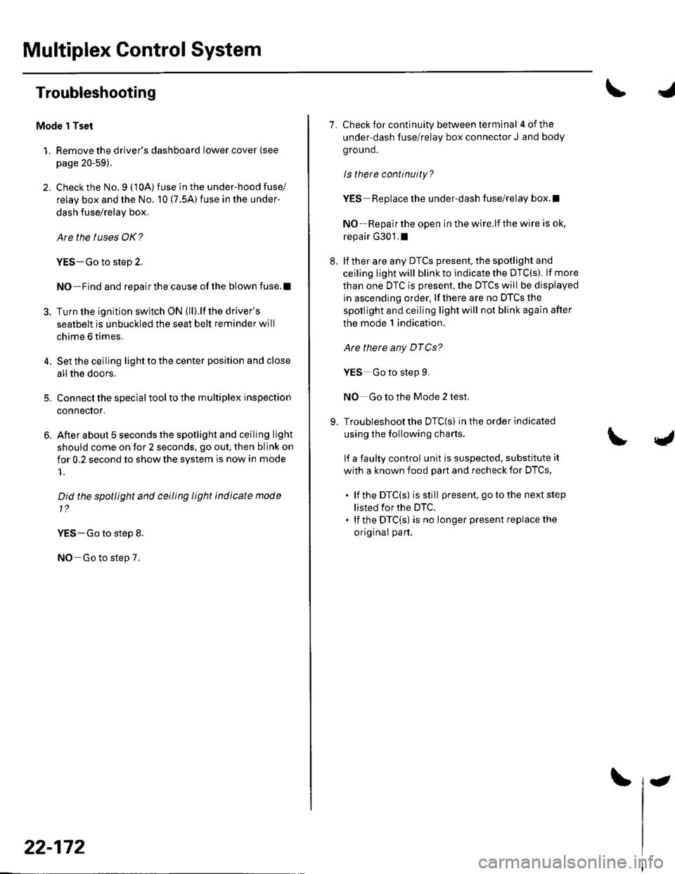
Mode 1 Tset
1. Remove the driver's dashboard lower cover {see
page 20-59).
2. Check the No. 9 ( 10A) fuse in the under-hood fuse/
relay box and the No. 10 (7.5A) fuse in the under-
dash fuse/relay box.
Are the fuses OK?
YES-Go to step 2.
NO-Find and repairthe cause ofthe blown fuse.!
3. Turn the ignition switch ON (ll).lf the driver's
seatbelt is unbuckled the seat belt reminder will
chime 6 times.
4. Set the ceiling light to the center position and close
allthe doors.
5. Connect the specialtoolto the multiplex inspection
conneclor.
6. After about 5 seconds the spotlight and ceiling light
should come on for 2 seconds, go out, then blink on
for 0.2 second to show the system is now in mode
1.
Did the spotlight and ceiling light indicate mode
1?
YES-Go to step 8.
NO Go to step 7.
22-172
-
7. Check for continuity between terminal 4ofthe
under-dash fuse/relay box connector J and body
ground.
ls there continuity?
YES Replace the under-dash fuse/relay box.l
NO - Repair the open in the wire.lf the wire is ok,
repair G301.1
8. lf ther are any DTCS present, the spotlight and
ceiling light will blink to indicate the DTC(S). lf more
than one DTC is present, the DTCS will be displayed
in ascending order, lf there are no DTCS the
spotlight and ceiling light will not blink again after
the mode 1 indication.
Are there any DTCg?
YES Go to step 9.
NO Go to the Mode 2 test.
9. Troubleshoot the DTC(S) in the order indicated
using the following charts.
lf a faulty control unit is suspected, substitute it
with a known food part and recheck for DTCS,
. lf the DTC(s) isstill present. go to the next step
listed for the DTC.. lf the DTC(S) is no longer present replace the
original part.
Page 1007 of 1139
Multiplex Control System
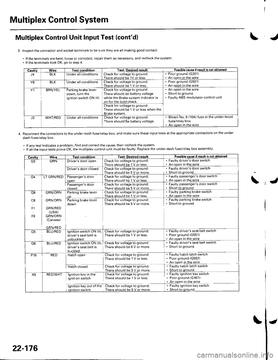
Multiplex Control Unit lnput Test (cont'd)
3. Inspect the connector and socket terminals to be sure they are all making good contact
.lftheterminalsarebent,looseorcorroded,repairthemasnecessary,andrecheckthesystem. llthe terminals look OK, go to step 4.
4. Reconnectthe connectorstothe under dash fuserelay box, and make surethese inputtests atthe appropriate connectors on lhe under-
dash fuse/relav box.
. lf any test indicates a problem, {ind and correct the cause, then recheck the system. lf allthe input tests prove OK, the multiplex control unit must be faulty. Replace the under_dash fuse/relay box assembly
CavitvWireTest conditionTest: Desired .esult r Possible cause if resullE qS!q!!e!!ed
J4BLK[J nder all conditionsCheck {or voltage 1o ground:Therc sholl.l he 1V or lessPoor ground (G20'l)An ooen in the wire
Y6BLKlJnder all conditionsCheck for voltage to ground:There should bc 1 V or less.Poor ground 1G501)An ooen in the wire
Y1BFNryELParking brake leverdown, turn theigntion switch ON (ll)
Check for voltage to ground:There should be battery voltagewhile the Brake system indicator ison forthe buld check.
An open in the wireShortto groundFaulty ABS modulatorcontrol unit
Check for voltage to ground:There should be 1V or less when the
J2WHT/REDUnder allconditionsCheck for voltage to groundiThere should be baftery voltage.Blown No.9 (10A)fuse in the under'hoodfuse/relay boxAn oncn in rhc wire
CavitvTest conditionTesi: Oesired resultPossible cause ifresult is notobtained
o3GRNDriver's door openCheck for voltage to ground:There should be 1 V or less-Faulty driver's door switchAn ooen in the wire
Driver's door closedCheck for voltage to ground:There should be 5 V or more.Faulty driver's door switchShort to qround
O4LT GRN/REDPassenger's doorCheck .for voltage 10 ground:There should be 1 V or less.Faulty passenger's door switchAn ooen inthewire
Passenger's doorCheck for voltage to ground:There should be 5 V or more.Faulty passenger's door switchShort to oround
osI]l.l
4.,
F1
F8
GRN/ORN
GRN/ORN
GRN/RED(USA)GRN/ORN(Canada)
Parking brake leverCheck for voltage to groLrnd:There shorl.l be 1 V or less.Faulty parking brake switch. An ooen in thewireCheck for voltage to ground:There should be 5 V or more.
. Faulty parking brake switchShortto ground
o5BLU/REDlgnition switch ON (ll),
driver's seat belt isCheck for voltage to ground:There should be 1V or less.Faulty driver's seat belt switchPoorground (G551)An oDen in the wire
Q6BLU/REDlgnition switch ON (ll)
driver's seat belt isbuckled.
Check {or voltage to ground:There should be 6 V or more.Faulty driver's seat belt switchShortto ground
P18RED
H",=
Check for voltage to ground:There sho0ld be 1V or less-
f -9*:li:'^:**:':s*:*
Faulty hatch latch swrtchPoor ground (G552)An open in the wireFaulty hatch latch switch
X5lgnirion key in the Check for voliage to gtound:ignit on switch Thpre should be I V or lcss
lgnrtron kev our o{ the Check for vollage to ground:
. Faulty ignition key switch. Poor ground (G401). An open in the wire
I : [11y.'::i':::1"' **6
\
22-176
Page 1009 of 1139
I
I
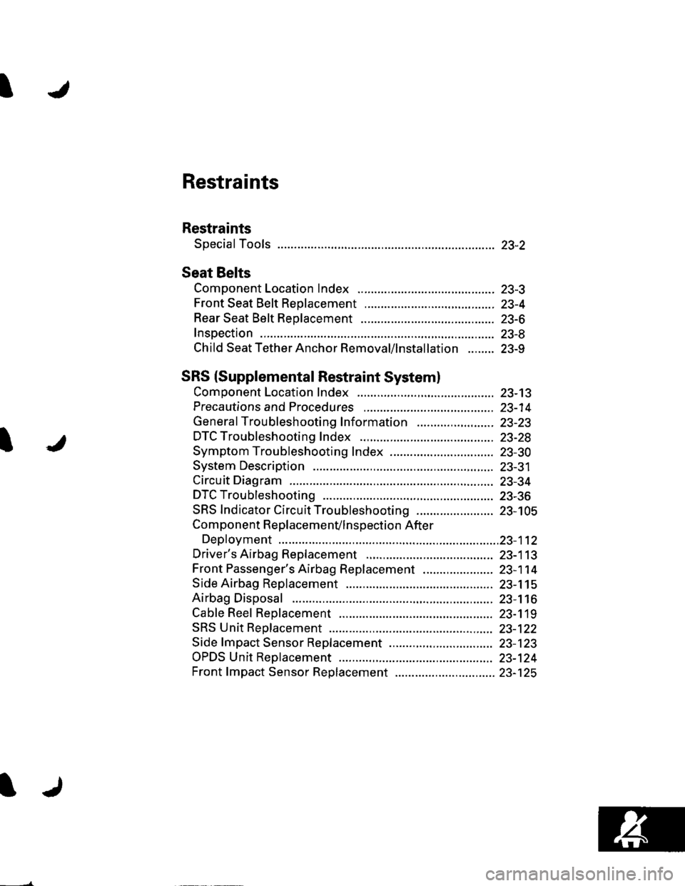
Restraints
Restraints
Special Tools ............. 23-2
Seat Belts
Component Location Index ......................................... 23-3
Front Seat Belt Replacement ....................................... 23-4
Rear Seat Belt Replacement ........................................ 23-6
Inspection .................. 23-8
Child Seat Tether Anchor Removal/lnstallation ........ 23-9
SRS (Supplemental Restraint Systeml
Component Location Index ......................................... 23-13
Precautions and Procedures ,,.,......... 23-14
General Troubleshooting Information ....................... 23-23
DTC Troubleshooting Index .............. 23-28
Symptom Troubleshooting Index ............................... 23-30
System Description ................. ........... 23-31
Circuit Diagram ......... 23-34
DTC Troubleshooting ............... .......... 23-36
SRS Indicator Circuit Troubleshooting ....................... 23-105
Component R e place me n(/ln s pect io n After
Deployment ..............23-112
Driver's Airbag Replacement ............ 23-113
Front Passenger's Airbag Replacement ..................... 23-1 14
Side Airbag Replacement .................. 23-115
Airbag Disposal ....................... ........... 23-116
Cable Reel Replacement .................... 23-119
SRS Unit Repfacement ....................... 23-122
Side fmpact Sensor Replacement ..........,.................... 23-123
OPDS Unit Replacement .................... 23-124
Front fmpact Sensor Replacement .............................. 23-125
Page 1011 of 1139
Seat Belts
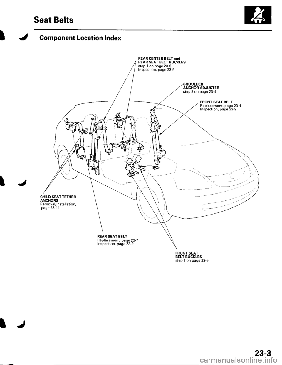
IComponent Location Index
CHILD SEATTETHERANCHORSRemoval/lnstallation,page 23-11
REAR CENTER BELT andREAR SEAT BELT BUCKLESstep 1 on page 23-8Inspection, page 23 9
SHOULDERANCHOR ADJUSTERstep 8 on page 23-4
FRONT SEAT BELTReplacement, page 23-4Inspection, page 23 9
I
REAR SEAT BELTBeplacement, page 23.7Inspection, page 23-9
FRONT SEATBELT BUCKLESstep 1 on page 23'6
23-3
Page 1012 of 1139
Seat Belts
Front Seat Belt Replacement
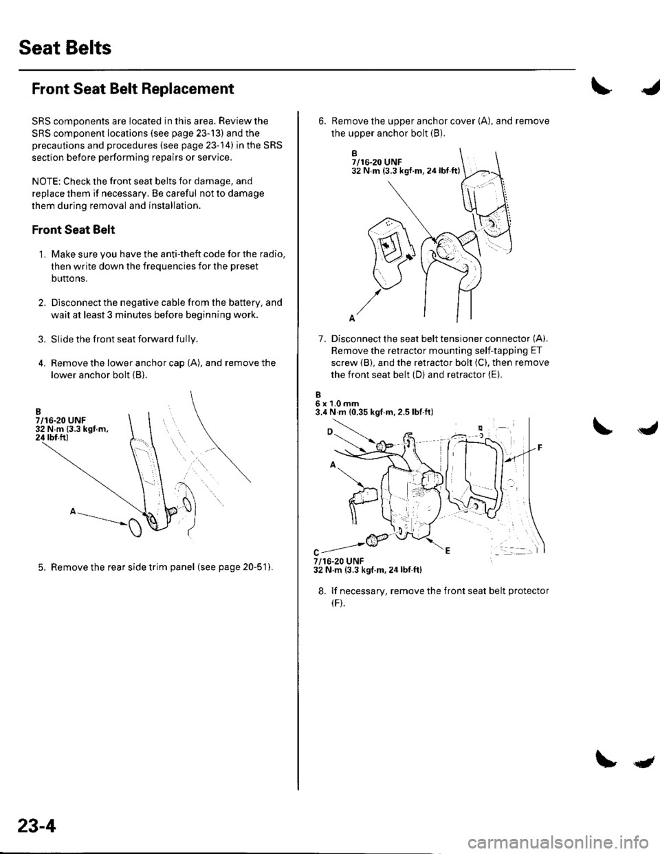
SRS comDonents are located in this area. Review the
SRS component locations (see page 23-13) and the
precautions and procedures (see page 23-14) in the SRS
section before performing repairs or service,
NOTE: Check the front seat belts for damage, and
replace them if necessary. Be careful not to damage
them during removal and installation.
Front Seat Belt
Make sure you have the anti-theft code for the radio,
then write down the frequencies for the preset
buttons.
Disconnect the negative cable from the battery, and
wait at least 3 minutes before beginning work.
Slide the front seat forward fully.
Remove the lower anchor cap (A), and remove the
lower anchor bolt (B).
3.
1.
5. Remove the rear side trim panel (seepage20-51).
23-4
qt
B7/16-20 UNF32 N m (3.3 kgf.m,24lbt.ft)
7. Disconnect the seat belt tensioner connector (A).
Remove the retractor mounting self-tapping ET
screw {B), and the retractor bolt (C), then remove
the front seat belt (D) and retractor (E).
6x1.0mm3.4 N m {0.35 kgf.m,2.5 lbf.ft)
6. Remove the upper anchor cover {A), and remove
the upper anchor bolt (B).
7/16-20 UNF32 N.m (3.3 kgf m,2ir lbf.ft)
8. lf necessary, remove the
(F).
front seat belt protecto
Page 1013 of 1139
9.
10.
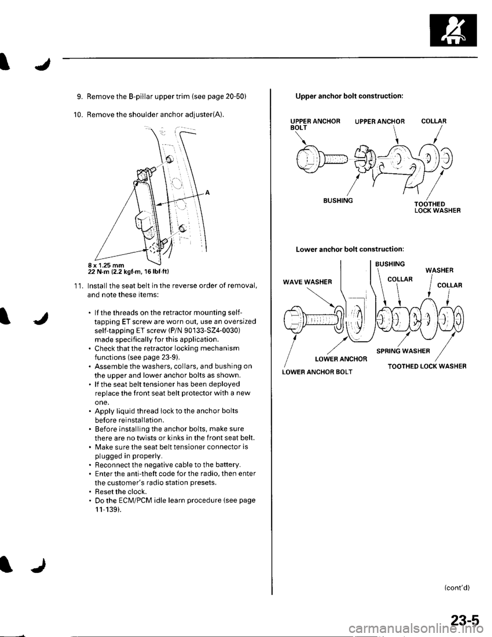
Remove the B-pillar upper trim {see page 20-50)
Remove the shoulder anchor adjuster{A).
22 N.m (2.2 kgf.m, 16lbf.ftl
Installthe seat belt in the reverse order of removal,
and note these items:
. lf thethreads on the retractor mounting self-
tapping ET screw are worn out, use an oversized
self-tapping ET screw (P/N 90133-SZ4-0030)
made specifically for this application.. Check that the retractor locking mechanism
functions (see page 23-9).. Assemble the washers, collars, and bushing on
the upper and lower anchor bolts as shown.. lf the seat belt tensioner has been deployed
replace the front seat belt protector with a new
one.. Apply liquid thread lock to the anchor bolts
before reinstallation.. Before installing the anchor bolts, make sure
there are no twists or kinks in the front seat belt.. Make sure the seat belt tensioner connector is
plugged in properly.
. Reconnect the negative cable to the battery.. Enter the anti-theft code for the radio, then enter
the customer's radio station presets.
. Reset the clock.. Do the ECM/PCM idle learn procedure {see page
11,139).
11.
8 x 1.25 mm
UPPER ANCHORBOLT
BUSHING
Upper anchor bolt construction:
UPPER ANCHOR
Lower anchor bolt construction:
COLLAR
TOOTHEDLOCK WASHER
LOWER ANCHOR BOLTTOOTHED LOCK WASHER
{cont'd)
WASHER
23-5
Page 1014 of 1139
Seat Belts
Front Seat Belt Replacement (cont'd)
Seat Belt Buckle
1. Make sure you have the anti-theft code for the radio,
then write down the frequencies for the preset
buttons.
2. Disconnect the negative cable from the battery ,and wait at least 3 minutes before beginning work.
3. Remove the front seat (see page 20-7'1).
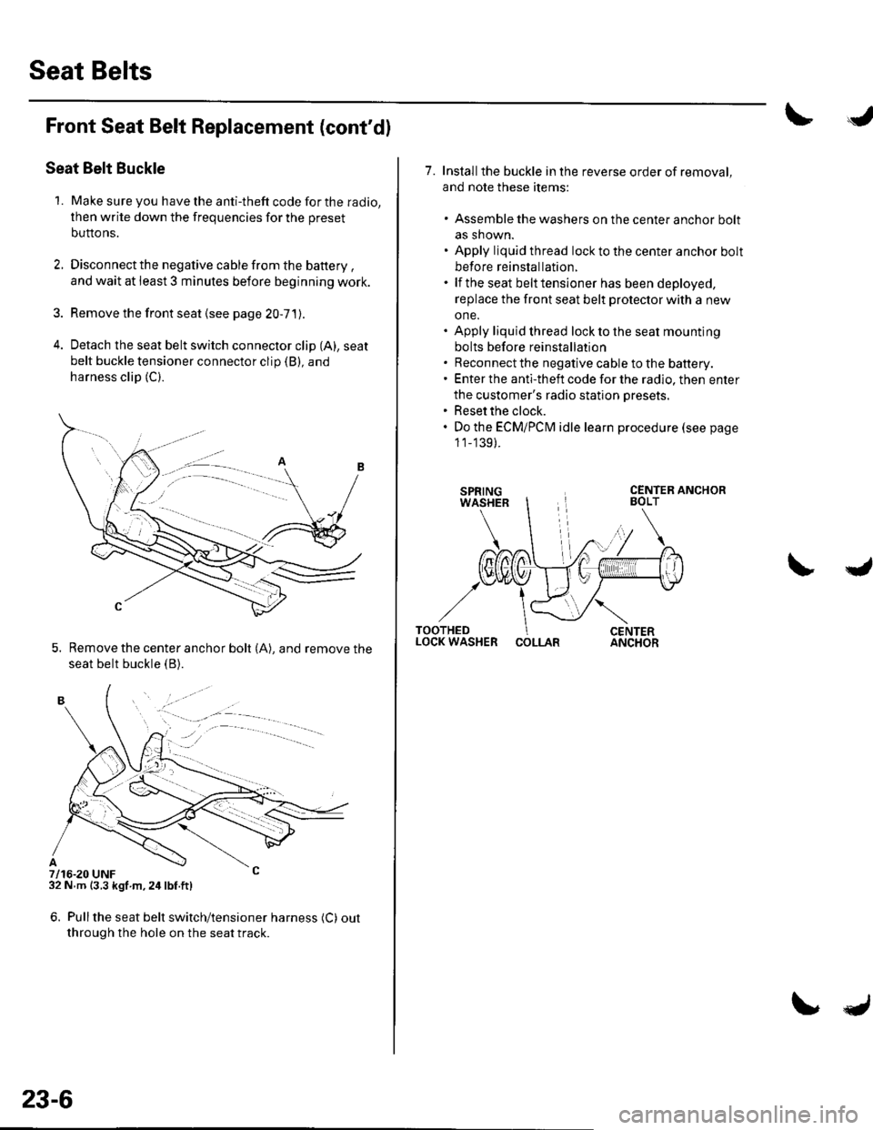
4. Detach the seat belt switch connector clip (A), seat
belt buckle tensioner connector clip (B), and
harness clip (C).
5. Remove the center anchor bolt (A), and remove the
seat belt buckle {B).
7/16-20 UNF32 N m {3.3 kgf m,24lbf.ft)
6. Pullthe seat belt switch/tensioner harness (C) out
through the hole on the seat track.
. -.. :.a--
23-6
7. Installthe buckle in the reverse order of removal,
and note these items:
. Assemble the washers on the center anchor bolt
as shown.. Apply liquid thread lock to the center anchor bolt
before reinstallation.. lf the seat belt tensioner has been deployed,
replace the front seat belt protector with a new
one.. Apply liquid thread lock to the seat mounting
bolts before reinstallation. Reconnect the negative cable to the battery.. Enter the anti-theft code for the radio, then enter
the customer's radio station presets.. Reset the clock.. Do the ECMiPCM idle learn procedure (see page
1 1_139).
COLLAR
Page 1015 of 1139
I
I
Rear Seat Belt Replacement
NOTE: Check the rear seat belts for damage, and
replace them if necessary. Be careful not to damage
them during removal and installation.
Rear Seat Belt
1. Remove the rear seat cushion (see page 20 80).
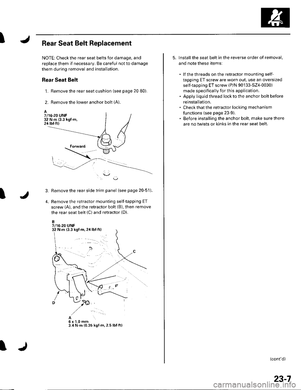
2. Remove the lower anchor bolt {A}.
l.\J,
Remove the rear side trim panel (see page 20-51).
Remove the retractor mounting self-tapping ET
screw (A), and the retractor bolt (B), then remove
the rear seat belt (C) and retractor {D).
B7/16-20 UNF
3,
4.
A6x1.0mm3.4 N.m {0.35 kgl m,2.5 lbf.ftl
A7/16-20 UNF32 N.m (3.3 kgf.m,24 tbf.ftl
N m {3.3 kgf.m,2ir lbf.ft)
5. Installthe seat belt in the reverse order of removal,
and note these items:
. lf the threads on the retractor mounting self-
tapping ET screw are worn out, use an oversized
self-tapping ET screw (P/N 90133-524-0030)
made specifically for this application.. Apply liquid thread lock to the anchor bolt before
reinstallation.' Check that the retractor locking mechanism
functions {see page 23-9).. Before installing the anchor bolt, make sure there
are no twists or kinks in the rear seat belt.
(cont'd)
23-7