2003 HONDA CIVIC belt
[x] Cancel search: beltPage 735 of 1139

IRear Seat-back Latch Replacement
1.Remove the seat-back (see page 20-80).
Remove the seat-back cover (see page 20-82).
Remove the seat-back pad {A) from the seat-back
frame (B). On right seat-back with center shoulder
belt, pass the center belt (C) through the hole in the
seat-back pad.
Remove the bolts, then remove the seat-back latch
(A) from the seat-back frame (B), and release the
pivot pin {C) of the latch lever (D) from the seat'
back f rame.
Fastener Locations
lnstallthe latch in the reverse order of removal, and
make sure the seat-back locks and unlocks properly.
\
Rear Seat-back Striker Replacement
NOTE: Take care not to scratch the interior trim.
1. Remove the rear side trim panel (see page 20-5'l).
2. Remove the bolts, then remove the seat-back
striker (A).
Fastener Locations
) : Bolt, 2
F
,-;1
8 x 1.25 mm22 N m 12.2 kgl rn,16 tbf.ft)
3. lnstallthe striker in the reverse order of removal,
and move the striker (A) up or down until it is
centered in the seat-back latch {B).
20-81
Page 736 of 1139

Seats
Rear Seat-back Cover Replacement
NOTE:. Take care not to tear the seams or damage the seat
covers.. Put on gloves to protect your hands.
'1. Remove the seat-back (see page 20-80).
Remove the headrest.
Pull up the latch cover (A) to telease the clips. then
remove it.
Fastener Locations
) : Clip, 4
1W
4.Pull up the outside edge of the latch lever cover (A)
to release the clips, and release the cover from thepivot pins (B) ofthe latch lever {C) while pulljng the
latch lever.
Fastener Locations
D : Clip, 2
i
*rJ
20-82
5. On right seat-backi Using a Torx T30 bit, remove
the bolts, then remove the belt holder trim (A), and
remove the trim from the center belt (B).
Fastener
) : Bolt,
A*-\./-
Locations6x1.0mm9.8Nm(1.0 kgf.m,7.2 lbf.ft)
Release the hook (A), and unzip the seat-back cover(B). The right seat-back is shown. the left seat-back
is similar.
\
Page 737 of 1139

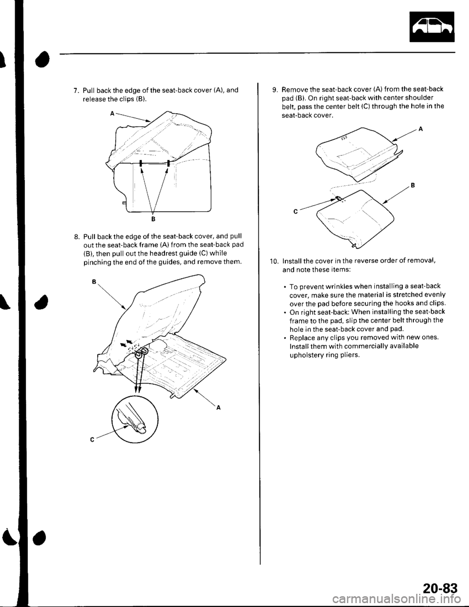
7. Pull back the edge of the seat-back cover (A), and
release the clips {B).
Pull back the edge of the seat-back cover, and pull
out the seat-back frame {A) from the seat-back pad
{B), then pull out the headrest guide (C) while
pinching the end of the guides, and remove them.
9. Remove the seat-back cover (A)from the seat-back
pad (B). On right seat-back with center shoulder
belt, pass the center belt (C) through the hole in the
seat-bacl( cover.
lnstallthe cover in the reverse order of removal,
and note these items:
. To prevent wrinkles when installing a seat-back
cover, make sure the material is stretched evenly
over the pad before securing the hooks and clips
. On right seat-back: When installing the seat-back
frame to the pad, slip the center belt through the
hole in the seat-back cover and pad.
. Replace any clips you removed with new ones.
Install them with commercially available
upholstery ring pliers.
10,
20-83
Page 865 of 1139

Connectors and Harnesses
Connector to Harness lndex (cont'd)
Floor Wire Harness (Front sidel
Connec-tor or TerminalI Refuavftres Location connects to Nol6sDriver's seat belt switchDriver's side airbag inflatorDriver's side impact sensorLeft side seat belt buckle tensionerMemory erase signal (MES) connectorParking brake switchPassenger's seat belt switchPassenger's side airbag inflatorPassenger's side impact sensorRight side seat belt buckle tensionerSRS unit connector BSRS unit connector CUnder-dash fuse/relay boxconnector P {see page 22-45)Under-dash fuse/relay boxconnector O (see page 22,45)c402
c403
c453
c508
c509
c512
11l013121995374202111
'r8
22
23
2
14
1
6
3 I Under driver's seat2 i Under driver's seat2 I Left side offloor4 Under driver's seat2 Under dash fuse/relay box1 1 Middle offloor3 Under passenger's seat2 Under passenger's seat2 Right side offloor4 Under passenger's seat18 I Under middle of dash8 Under middle of dash18 Underdash fuse/relay box
8
]
Under dash fuse/relay box
10
I
Under middle of dash
4 Under middle of dash
6 Under middle of dash
4 Under middle of dash
6 Under middle ofdash
8
I
Under middle of dash
10 Under middle of dash
4 ] Unaer middle of aasn
Dashboard wire harness B{see page 22 30)Dashboard wire harness B(see page 22-30)ECM wire harness (see page22-321Dashboard wire harness A(see page 22-26)Dashboard wire harness A\see page 22-26)Dashboard wire harness A{see page 22-26)Engine compartment wireharness (see page 22 18)OPDS unit harness (see page22-421G551IL,nder passenger's seatBody ground via floor wire
22-34
Page 867 of 1139

Gonnectors and Harnesses
a
Floor Wire Harness {Rear side}(cont'dl
Cargo areaDriver's door switchEVAP emission bypass solenoid valveEVAP emission control canister ventshut valveFuel pump/sending unitFuel tank pressure sensorLeft back-up lightLeft rear ABS wheel sensorLeft rear side marker lightLeft rear speakerLeft rear turn signal lightLeft side seat belt tensionerLeft taillighVbrake lightNoise condenser (rear windowdefogger)Noise condenser (rear window wiper)Passenger's door switchRear window wiper intermiftentcontrolunitRight back-up lightRight taillighvbrake tightRight rear turn signal lightBight rear ABS wheel sensorRight rear side marker lightRight rear speakerRight side seat belt tensioner
c554
Fueltank
FueltankFueltankLeft taillightLeft rear offloorBehind left side of rear bumperLeft quarter panelLefttaillightLeft B-pillarLeft taillightRight quarter panel
Right quarter panelRight B pillarRight q uarter panel
Right tai ightRight taillightRight taillightRight side of cargo area
side of cargo areaLeft B pillarFueltank
Right quaner panel
6224
I32512642A527'13
181011
222021151912117
I
2122
5322222232
232222212
12
2120
Behind right side of rear bumperRight quaner panelRight B-pillarRight quaner panelHatch wire harness (see page22 39)Hatch wire harness (see page
rear seal bdcl Bodv ground vta
Right side of cargo area Body ground via floor wire
Connector to Harness Index (cont'dl
22-36
Page 879 of 1139

Ground Distribution
Ground to Components Index
GroundComponent or circuit qrounded
Batterv, Transmission housinq
E ngine
G 101ECM (PG is BLK; LG is BRN/YEL)
BLK: IAC valve, lgnition coils, Vehicle speed sensor, VTEC solenoid valve
BRNA/EL: Camshaft oosition (CMP) sensor. CKP sensor, TDC sensor. VTEC oil pressure switch
G 15'�]EPS control unit
G201ELD unit. Multiplex control inspection connector, Multiplex control unit, Power window relay, Rear
window washer motor, Right front parking light, Right front side marker light, Right front turn signal
light, Turn signal/hazard relay, Washer fluid level sensor (Canada) , Windshield washer motor,
Windshield wiDer motor
G202ABS modulator-control unit
G301
G401
Blower motor relay, Brake fluid level switch, Condensor fan motor, Cruise control actuator, Left front
parking light, Left front side marker light, Left front turn signal light, Radiator fan motor, Radiator fan
swrtcn
Combination liqht switch, lqnitlon kev srvitch, Wiper/wasfrer sr,virch
G402Left and riqht airbaq sensors, SRS unit
G 451Data link connector (DLC)
G501Clutch interlock switchm Clutch pedal position switch (for cruise control), Cruise control main switch,
Cruise control unit, Daytime running lights control unit (Canada), Driver's door lock knob switch,
Driver's door lock switch, Driver's power window motor, Heater control panel, Left power mirror
defogger (Canada), left side turn signal light, Moonroof control unit, Monroof open and close relays,
Moonroof position sensor '1, Moonroof seitch, Power mirror switch, Power transistor, Power window
master switch. SDotliqhts
G502Accessory power socket, Gauge assembly, Keyless receiver unit, lvlultiplex control unit, Right power
mirror defogger {Canada)
G503Audio unit
G551Driver's seat belt switch, Fuel gauge sending unit, Fuel pump, Memory erase signal (IMES) connector,
OPDS unit. Rioht seat belt switch
G552High mount brake light, License plate lights, Rear window defogger, Rear window defogger noise
condenser. Rear window wioer motor, Hatch latch switch
Back-up lights, Brake lights, Rear side marker lights, Rear turn signal lights, Rear window wiper noise
condenser, Rear window wiper intermittent control unit, Taillights
22-48
Page 887 of 1139

Gauges
Self-diagnostic Procedure
The gauge assembly has a self-diagnosis function.. The Beeper Drive Circuit Check. The Indicator Drive Circuit ChecL. The LCD Segments Check. The Gauges Drive Circuit Check (Speedometer, Tachometer, Fuel gauge, Coolant temperature gauge). The Communication Line Check (the coolanttemperature signal line between the gauge and ECM)
NOTE: Indicators are also controlled via the communication line.
Entering the self-diagnosis f unction:
Before doing the self-diagnosis function, check the No. 9 (10A) fuse in the under-hood fuse/relay box and No. 10 {7.5A)fuse in the under'dash fuse/relay box.
1. Push and hold the trip/reset button.
2. Turn the lighting switch ON.
3. Turn the ignition switch ON (ll).
4. Within 5 sec., turn the lighting switch OFF, then ON and OFF again.5. Within 5 sec., release the trip/reset button, then push and release the button four times reDeatedlv.
NOTE:. While in the self-diagnosis mode, the dash lights brightness controller operates normally.'Whileintheself-diagnosismode,thetrip/resetbuttonisusedtostartthebeeperdrivecircuitcheckandthegauge
drive cicuit check.. lf the vehicle speed exceeds 1.2 mph 12 km/h) orthe ignition switch is tu rned OFF, the self,diag nosis mode ends.
oN flrl
lgnition
Switch
Lighting
Switch
Trip/Reset
Switch-> Move to selt-diagnosis mode.
5 sec.5 sec.
The Beeper Drive Circuit Check:
When entering the self-diagnosis mode, the beeper sounds five times
The Indicator Drive Circuit Check:
When entering the self-diagnosis mode, the following indicators blink.
Seat belt indicator, Door/hatch indicator, Brake system, Lowfuel indicator, Maintenance required indicator (USA),
Washer fluid level indicator (Canada), Oil pressure light.
v
OFF
22-56
Page 1002 of 1139

ISystem Descriptions
The Multiplex Control System has four internal
functions:. Multiplexing (send multiple signals over sharedwtres). Wake up/sleep (runs at full power only on demand toreduce battery draw). Fail-safe (fixes or ignores faulty signals). Self-diagnosis (Mode 1 for the system, Mode 2 for
input lines)
The system controls the function of these circuits:. Entry lightcontrol (ignition key lightandceiting light). Wiper/washer intermittent wipe and park functions. Keyless/power door lock. Meter assembly, temperature gauge, and indicator
lights. HVAC (compressor and fan control). Key-in reminder. Headlight reminder. Seatbelt reminder
JI
/ar
22-171
Multiplex Communication
To reduce the number of wire harnesses, digital signals
are sent via shared multiplex communication linesrather than sending normal electrical signals throughindividual wires.. The input signals from each switch are converted todigital signals at the central processing unit (CpU).. The digital signalsaresentfromthetransmitting unitto the receiving unit as serial signals.. The transmitted signal is converted to a switch signalat the receiving unit, and it operates the related
component or monitors a swltch.. There are exclusive communicalion lines between
the ECM, the gauge assembly, and the under,dash
fuse/relay box.
Wake-up and Sleep
The multiplex control system has "wake-up" and"sleep" functions to decrease parasitic draw on the
battery when the ignition switch is OFF.. ln the sleep mode, the multiplex control unit stops
functioning (communication and CPU control) when it
is not necessary for the system to operate.. As soon as any operation is requested (for example, adoor is unlocked), the related control unit in the sleep
mode immediately wakes up and begins to function.. When the ignition switch is turned OFF, and the
driver's or front passenger's door is opened, then
closed, there is about a 10 second delay before the
control unit goes from the wake-up mode to the sleepmode.. lf any door is open, the sleep mode will not function.. lf a key is in the ignition switch, the sleep mode will
not function.. When in sleep mode, the draw is reduced from
70 80 mA to less than 10 mA.
Fail-safe
To prevent improper operation, the multiplex controlsystem has a fail-safe function. In the fail-safe mode,
the output signal js fixed when any part of the systemmalfunctions (for example a faulty control unit orcommunication line).
Each control unit has a hardware fail-safe function thatfixes the output signal when there is any CPUmalfunction, and a software fail-safe function thatignores the signal from the malfunctioning control unitand allows the system to operate normally.