Page 44 of 1139

Starter Replacement
1. Make sure you have the anti-theft code for the radio.
then write down the frequencies for the radio's
preset buttons.
2. Disconnect the negative cable from the battery first,
then disconnect the positive cable.
3. Disconnect the knock sensor connector.
4. Remove the bolt (A) securing the harness bracket,
then remove the intake manifold bracket (B).
A6x1,0mm12 N.m {1.2 kgf.m,8.7 tbt.ft)
8 x 1.25 mm22 N,m 12.2 kgt.m,16 rbf.ftl
L't2.
4-9
5. Disconnect the starter cable (A)from the B terminal
on the solenoid, then disconnect the BLK,/WHT wire
{B) from the S terminal.
10 x 1.25 mm44 N.m {a.5 kgf.m,33lblft)
8 x 1.25 mm9Nm10.9 kgf.m,7 lbl ft)
7.
9.
'10.
11.
2
S'-12x12smm6ilNm{6.5 kgl m,47lbfft)
Remove the two bolts holding the starter, then
remove the starter.
lnstall the starter in the reverse order of removal.
Make sure the crimped side of the ring terminal (A)
is facing out.
Connect the positive cable and negative cable to
the batterY.
Start the engine to make sure the starter operates
propeny.
Enter the anti-theft code for the radio, then enter
the customer's radio station presets.
Set the clock.
Perform the engine control module (EcM) idle learn
procedure (see page 1 '1- 139 ).
I
Page 82 of 1139
Engine Assembly
I
Engine Removal
Special Tools Required
Front subframe adapter EOS02C00001 1
NOTE:. Use fender covers to avoid damaging painted
surfaces.. To avoid damage, unplug the wiring connectors
carefully while holding the connector portion.. Mark all wiring and hoses to avoid misconnection.
Also, be sure that they do not contact other wiring orhoses, or interfere with other parts.
1. Secure the hood in the wide open position (support
rod in the lower hole).
2. Make sure you have the anti-theft code for the radio,
then write down the frequencies for the radio'spreset buttons.
3. Disconnect the negative cable from the battery first,then disconnect the positive cable.
4. Remove the battery.
5. Remove the intake manifold cover.
II
5-2
\,
6. Disconnectthe intake airtemperature (lAT) sensorconnector (A), remove the breather hose (B) and
vacuum hose (C), then remove the air cleaner
housing cover/intake air duct assemblv (D).
AC
7. Remove the air cleaner housing.
Page 117 of 1139
Gylinder Head
Cylinder Head Cover Removal
1. Remove the intake manifold cover.
2. Remove the four ignition coils (see page 4-'18).
3. Remove the dipstick (A) and breather hose (B).
6-22
\-
\
4, Remove the cylinder head cover
V:t :;t 1
|
,'.i/
(
(
Page 118 of 1139

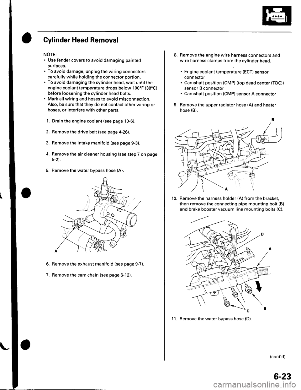
Gylinder Head Removal
NOTE:. Use fender covers to avoid damaging painted
surfaces.
To avoid damage, unplug the wiring connectors
carefully whlle holding the connector portion.
To avoid damaging the cylinder head, wait until the
engine coolant temperature drops below 100'F (38"C)
betore loosening the cylinder head bolts.
Mark all wiring and hoses to avoid misconnection.
Also, be sure that they do not contact other wiring or
hoses, or interfere with other parts.
'1.
2.
3.
Drain the engine coolant (see page 10-6).
Remove the drive belt (see page 4-26).
Remove the intake manifold {see page 9-3).
Remove the air cleaner housing (see step 7 on page
5-2t.
5. Remove the water bypass hose (A).
Remove the exhaust manifold (see page 9-7
Remove the cam chain (see page 6-12).
6.
7.
).
8. Remove the engine wire harness connectors and
wire harness clamps from the cylinder head.
. Engine coolant temperature (ECT) sensor
conneclor. Camshaft position (Cl\4P) (top dead center (TDC))
sensor B connector. Camshaft posilion (CMP) sensor A connector
9. Remove the upper radiator hose (A) and heater
hose (B).
'10. Remove the harness holder (A)from the bracket,
then remove the connecting pipe mounting boh {B)
and brake booster vacuum line mounting bolts {C).
(cont'd)
1 1. Remove the water bvpass hose (D).
6-23
Page 183 of 1139
Engine Mechanical
Intake Manifold and Exhaust System
lntake Manifold Removal and Installation ................. 9-2
Exhaust Manifold Removal and Installation .............. 9-7
Exhaust Pipe and Muffler Replacement ..................... 9-8
r
r-!i!1
Page 184 of 1139
Intake Manifold and Exhaust System
lntake Manifold Removal and Installation
Exploded View:
INTAKE MANIFOLD PLATEReplace if cracked orif mating surface isdamaged.
6x1.0mm12 N.m{1.2 kgf.m,8.7 lbf.ft)
\
I
GASKETReplace.
8 x 1.2522Nm12.2 ksf
\
\8x22
k'e)
t9
w)
k
('!
16
.25 mm'mkgf.m, 1
8 x 1.25 mm22 N.m(2.2 kgf m. 16 lbt.ft)
(
8 x 1,25 mm22 N.m {2.2 kgf.m, 16 lbf ft}
INTAKE MANIFOLDReplace if cracked orif mating surface is
9-2
\-
Page 185 of 1139
Removal:
'1. Remove the intake manifold cover.
2.Remove the evaporative emission (EVAP) canister
hose (A), brake booster vacuum hose (B), and
vacuum hoses {C).
3. Disconnectthe intake airtemperature (lAT) sensor
connector (A), and remove the breather hose (B),
then remove the air cleaner housing cover/intake
air duct assembly (C).
4.Fully open the throttle link and cruise control link
by hand, then remove the throttle cable (A) and
cruise control cable (B) from the links. Loosen the
locknuts {C). and remove the cables from the
bracket.
(cont'd)
(
9-3
Page 186 of 1139
Intake Manifold and Exhaust System
Intake Manifold Removal and Installation (cont'dl
5. Be prepared to catch and clean up spilled coolant.
Remove the water bypass hoses, then plug the
water bypass hoses.
6. Relievefuel pressure (see page 11-'144).
7. Remove the fuel line (seepagell-149).
8. Remove the positive crankcase ventilation (PCV)
hose (A), harness holder mounting bolt (B) and
harness clamp mounting bolt (C).
9-4
\-
(
9.Remove the engine wire harness connectors and
wire harness clamps from the intake manifold.
. Four injector connectors. ldle air control (lAC) valve connector. Throttle position (TP) sensor connector. fvlanifold absolute pressure {lvlAP) sensor
connector. Evaporative emission (EVAP)canister purge
valve connector
Remove the bolt securing the intake manifold and
bracket.
'1 0.
11.Remove allthe intake manifold mounting bolts/
nuts.
Remove the two stud bolts (A), then remove the
intake manifold (B).
1'>