Page 23 of 1139

L
v
2-11
Design Specifications
O
o
o
|temMeasurementOualificationSpecilication
DIMENSIONSOveralllength4,210 mm {165.8 in.)
Overallwidth1,695 mm 166.7 in.)
Overallheight1,440 mm (56.7 in.)
2,570 mm (101.2 in.)
Trackrront1,470 mm (57.9 in.)
Rear'1,470 mm (57.9 in.i
Ground clearance152 mm (5.98 in.)
Seating capacityfour {4)
wEtGt-iT {u.s.A.)Gross Vehicle Weight Rating
(GVWR)
3,660 rbs
WEIGHT
(CANADA)
Gross Vehicle Weight Rating
{GVWR)
1,660 kg
ENGIN ETvpeWater cooled. 4 stroke DOHC V-EC engin(
Cylinder arrangementInline 4'cylinder, transverse
Bore and stroke86 x 86 mm (3.39 x 3.39 in.)
Displacement1,998 cm'(122 cu in.)
Compression ratio9.8
Valve trainChain drive. DOHC VTEC 4 valves per cylinder
Lubrication systemForced, wet sump, with trochoid pumP
Oil pump displacementAt 6,000 engine
rpm
54.3 0 (57.4 US qo/minute
Water pump displacementAt 3,400 engine82 0 (87 US qt)/minute
F!el requiredUNLEADED gasoline with 86 pump octane number or higher
STARTERTvpeGear reduction
Normaloutput
Nominalvoltage12V
Hour rating30 seconds
Direction of rotationClockwise as viewecl from gear end
CLUTCHClutch tvpeSinqle plate dry, diaphragm spring
Clutch friction material surface area174 cm'{26.97 sq in.)
I\,1AN UAL
TRANSMISSION
TvpeSvnchronized, s-speed forward, 1 reverse
Primarv reductionDirect 1:1
Gear ratiolst3.062
2nd1.769
3rd1.212
4th0.921
5th0.738
Reverse3.583
FinalreductionTypeSinole helicalgear
Gear ratio4.164
Page 127 of 1139

Gylinder Head
Valve Inspection
1.Remove the valves (see page 6-31),
Measure the valve in these areas.
lntake Valve Dimensions
A Standard lNewl: 34.85 35.15 mm
B Standard {Newl:
C Standard lNew):
C Service Limit:
B Standard (New):
C Standard (New):
C Service Limit:
Exhaust Valve Dimensions
A Standard (New): 29.85-30.15 mm
{1.372 1.384 in.l
108.7 - 109.5 mm
14.280- 4.311 in.)
5.475 5.485 mm
10.2156-0.2159 in.)
5.445 mm {0.214 in.l
(1.175- 1.187 in.)
108.3 109.1 mm
(4.264- 4.295 in.l
5.450 5.460 mm(0.2146 0.2150 in.)
5.42 mm (0.213 in.)
2.
.<
6-32
t-
Valve Stem-to-Guide Clearance\
Inspection
1.Remove the valves (see page 6-3'1).
Slide the valve out of its guide about 10 mm. then
measure the guide-to-stem clearance with a dial
indicator while rocking the stem in the direction of
normal thrust (wobble method).. lf the measurement exceedsthe service limit,
recheck it using a new valve.. lf the measurement is nowwithin the service
limit, reassemble using a new valve.. lf the measurementwith a newvalve still
exceeds the service limit, go to step 3.
lntake Valve Stem-to-Guide Clearance:
Standard lNew): 0.06 0.11 mm
{0.002 0.004 in.}
Service Limil: 0.16 mm {0.006 in.)
Exhaust Valve Stem-to-Guide Clearance:
Standard lNewl:0.11 -0.16 mm
10.004 0.006 in.)
Service Limit: 0.22 mm 10.009 in.)
Subtract the O.D. of the valve stem. measured with
a micrometer, from the LD. of the valve guide,
measured with an inside micrometer or ball gauge.
Take the measurements in three places along the
valve stem and three places inside the valve guide.
The difference between the largest guide
measurement and the smallest stem measurement
should not exceed the service limit
lntake Valve Stem-to-Guide Clearance:
Standard (New): 0.030 0.055 mm
{0.0012 0.0022 in.)
Service Limit; 0.08 mm (0.003 in.l
Exhaust Valve Stem-to-Guide Clearance:
Standard {Newl: 0.055 0.080 mm(0.0022-0.003r in.l
Service Limit: 0.11 mm (0.004 in.)
(
3.
4,.
I
Page 453 of 1139

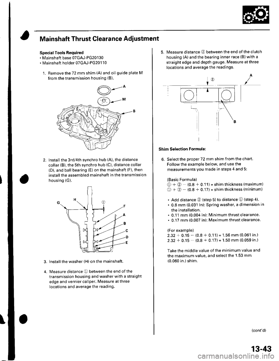
Mainshaft Thrust Clearance Adiustment
Special Tools Required. Mainshaft base 07GAJ-PG20130. Mainshaft holder 07GAJ-PG20110
1. Remove the 72 mm shim (A) and oilguide plate M
from the transmission housing (B).
,5---ov/
Installthe 3rd/4th synchro hub (A), the distance
collar (B), the 5th synchro hub {C). distance collar
(D), and ball bearing (E) on the mainshaft (F), then
installthe assembled mainshaft in the transmission
housing (G).
lnstall the washer (H) on the mainshaft.
Measure distance O between the end of the
transmission housing and washer with a straight
edge and vernier caliper. Measure at three
locations and average the reading.
5.Measure distance @ between the end of the clutch
housing (A) and the bearing inner race (B)with a
straight edge and depth gauge. Measure at three
locations and average the readings.
A
Shim Selection Formula:
6, Select the proper 72 mm shim from the chan.
Follow the example below, and use the
measurements you made in steps 4 and 5:
(Basic Formula)
O+@ (0.8 * 0.11) = shim thickness (maximum)
O + O (0.8 + 0.17) = shim thickness (minimum)
. Add distance O (step 5) to distance O (step 4)
. 0.8 mm (0.031 in): Spring washer, a dimension in
the installation.. 0.11 mm (0.004 in): lvlinimum thrust clearance
. 0.17 mm (0.007 in): Maximum thrust clearance.
(For example)
2.32 + 0.15 - (0.8 + 0.11)= 1.56 mm (0.061 in.)
2.32 + 0.15 - (0.8 + 0.17)= 1.50 mm (0.059 in.)
Take the middle value of the minimum value and
the maximum value, and select the 1.53 mm
(0.060 in.) shim.
{cont'd)
13-/li|
Page 458 of 1139
Manual Transmission
Transmission Reassembly (cont'dl
9. Install the 14 x 20 mm dowel pins (A).
34 N.m(3.5 kgf.m,25 rbf.ft)
Set the tapered cone ring (B) as shown. Place the
transmission housing over the clutch housing,
being careful to line up the shafts.
10.
13-48
11. Lower the transmission housing the rest of the wayas you expand the 72 mm snap ring {C). Release
the snap ring so it seats in the groove of the
countershaft bearing.
12. Check that the 52 mm snap ring is securely seatedin the groove of the countershaft bearing.
Dimension O as instalted: 3.3 6.0 mm
{0.13 0.24 in.l
Apply liquid gasket (P/N 08718-0001) to the threads
of the 32 mm sealing cap {D), and install it on thetransmission housing,
Install the transmission hangers A. and B, and the
8 mm flange bolts finger-tight.
13.
't4.
15.
8 x 1.25 mm27 N.m(2.8 kgf.m.20 rbf.ft)
(t
\A
e././
Tighten the 8 mm flange bolts in a crisscross
Pattern In several steDs.
(