Page 828 of 1139

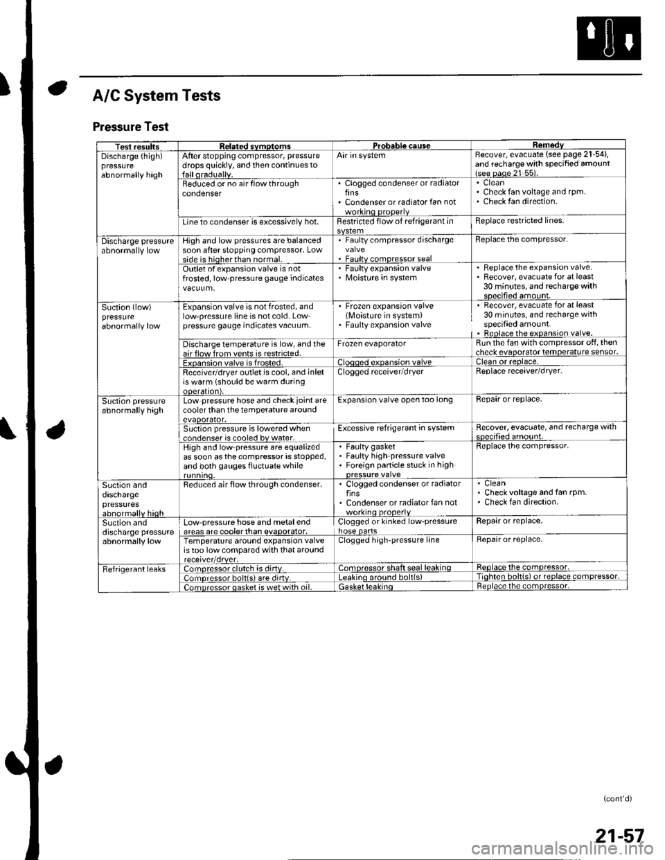
A/C System Tests
Pressure Test
Test resultssvmotom3DGaUSeDischarge (high)pressureabnormally high
After stopping compressor, pressure
drops quickly, and then continues toAir in systemRecover, evacuate (see page 21-54),and recharge with specified amount{see oaoe 21 55).
Beduced or no air flow throughcondenserClogged condenser or radiatorfinsCondenser or radiator fan not
CleanCheck fan voltage and rpm.Check fan direction.
Line to condenser is excessively hot.Restricted flow of refrigerant inReplace restricted lines.
Discharge pressureHigh and low pressures are balancedsoon after stopping compressor, Lowside is hioherthan normal.
. Faulty compressor dischargevalve. Faultv comoressor seal
Beplace the compressor.
Outlet of expansion valve is notfrosted, low pressure gauge indicatesFaulty expansion valveMoisture in system
. Replace the expansion valve.. Recover, evacuate for at least30 minutes, and recharge withsDecified amount.
Suction (low)pressureabnormally low
Expansion valve is not frosted, andlow-pressure line is not cold. Lowpressure gauge indicates vacuum,
' Frozen expansion valve(Moisture in system). Faulty expansion valve
Recover, evacuate for at least30 minutes, and recharge withspecified amount.Beplace the expansion valve.
Discharge temperature is low, and theair flow from vents is restricted.Frozen evaporatorRun the fan with compressor off, thencheck evaooratot temoerature sensor.
Exoansion valve is frosted.ean or reolace,
Receivetdryer outlet is cool, and inletis warm (should be warm duringooeralton),
Clogged receiver/dryerReplace receaver/dryer.
Suction pressureabnormally highLow pressure hose and check joint arecooler than the temperature aroundevaoorator,
Expansion valve open too longBepair or replace.
Suction pressure is lowered when..nrlenser is cooled bv water.Excessive refrigerant in systemRecover, evacuate, and recharge withqnp.ifie.lamo'rnr
High and low pressure are equalizedas soon asthecompressor is stopped,and both gauges fluctuate while
Faulty gasketFaulty high pressure valveForeign panicle stuck in high
Replace the compressor.
Suction anddaschargepressuresabnormallv hioh
Reduced air flow through condenser.. Clogged condenser or radiatorfins' Condenser or radiator fan notworkino orooerlv
CleanCheck voltage and fan rpm.Check fan direction.
Suction anddischarge pressureabnormally low
Low-pressure hose and metalendareas are coolerthan evaoorator,Clogged or kinked low-pressurehose oartsRepair or replace.
Temperature around expansion valveis too low compared with that aroundClogged high-pressure lineRepair or replace,
Fefrigerant leaks:omoressor clulch is dirtv.:omoressor shaft seal leakinqReolace the comDressor,
lomoressor bolt(s) are dirtv.no around bolt(s)Tiohten bolt{s) ot reolace comDressor,
;omDressor oasket is wet with oil.ietnoace the comoressor.
(cont'd)
21-57
Page 829 of 1139

Heating and Air Conditioning
A/C System Tests (cont'd)
1.
Performance Test
Air conditioning refrigerant or lubricant vapor
can irritate your eyes, nose, or throar.
Be carefulwhen connecting service equipment.
Do not breathe refrigerant or vapor.
The performance test will help determine if the air
conditioner system is operating within specifications.
Use only service equipment that is U.L.-listed and is
cenified to meet the requirements of SAE J2210 toremove HFC-134a (R-134alfrom the air conditioning
system.
lf accidental system discharge occurs, ventilate the
work area before resuming service
R-134a service equipment or vehicle air conditioning
systems should not be pressure tested or leak testedwith compressed air.
Additional health and safety information may be
obtained from the refrigerant and lubricant
manufacturers.
Connect a R-134a refrigerant recover/recycling/
charging station to the high-pressure service port
and the low-pressure service port, following the
equipment manufacturer's instructions.
Determine the relative humidity and air
Iemperaru re.
' Compressed air mixed with R-134a forms a
combustible vapor.. The vapor can burn or explode causing serious
Injury.. Never use compressed air to pressure test
R-134a service equipment or vehicle air
conditioning systems.
21-58
4.
Open the glove box. Remove both glove box stops,
then let the glove box hang down (see page 20-63).
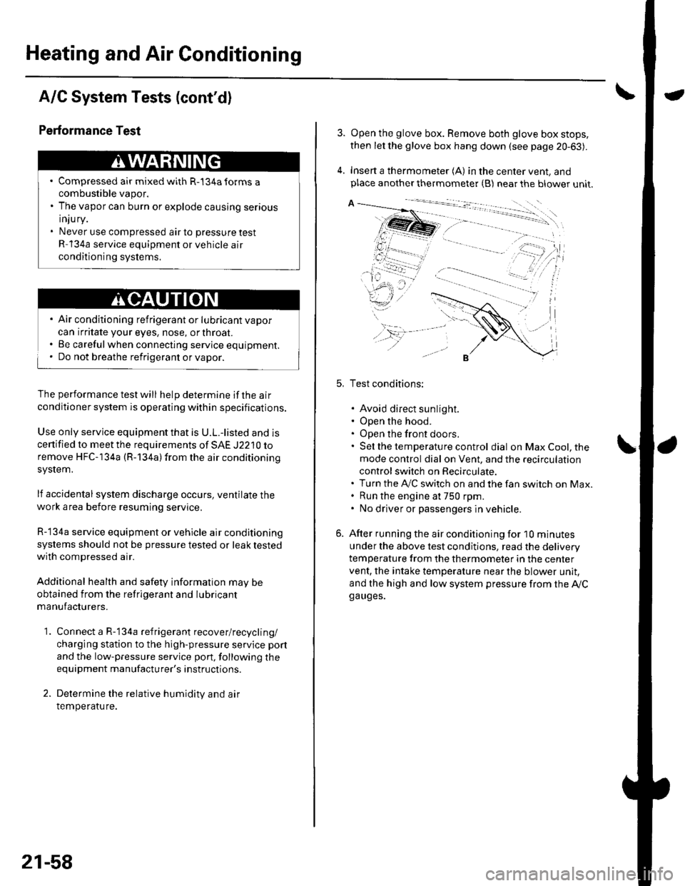
Insert a thermometer (A) in the center vent, andplace another thermometer {B) near the blower unit.
Test conditions:
. Avoid direct sunlight.. Open the hood.. Open the front doors.. Sel the temperature control dial on Max Cool, the
mode control dial on Vent, and the recirculation
control switch on Recirculate.. Turn the A,/C switch on and the fan switch on Max.. Run the engine at 750 rpm.. No driver or passengers in vehicle.
After running the air conditioning for I0 minutes
under the above test conditjons, read the delivery
temperature from the thermometer in the center
vent, the intake temperature near the blower unit,
and the high and low system pressure from the Ay'Cga uges.
Page 880 of 1139

Under-dash Fuse/Relay Box
Removal and Installation
SRS components are located in this area. Review the
SRS component locations {see page 23-13) andprecautions and procedures (see page 23-14) in the SRS
section before performing repairs or service.
Removal
1. Make sure you have the anti-theft code for the radio,
then write down the frequencies for the radio's
preset buttons.
2. Disconnectthe battery negative cable, then
disconnect the positive cable, and wait at least
three minutes.
3. Remove the driver's dashboard lower cover (see
page 20-59).
4. Disconnect the connectors from the fuse side of the
under-dash fuse/relay box.
5. Remove the mounting bolt, and slide the under-
dash fuse/relay box (A) down from the bracket {B).
6. Disconnect the back side from connectors from the
back of the under-dash fuse/relay box, and remove
the fuse/relay box.
NOTE:The SRS connector is a spring-loaded lock
type (see page 23-1 1).
lnstallation
1. Installthe under-dash fuse/relay box in the reverse
order of removal and connect all connectors to the
under-dash fuse/relay box.
2. Installthe driver's dashboard lower cover.
3. Connect both the negative cable and positive cable
to the battery.
4. Enter the anti-theft code for the radio, then enter
the customer's radio station presets.
5. Confirm that all systems work properly,
6. Do the engine control module (ECM) idle learn
procedure (see page 11-139).
22-49
Page 884 of 1139
lgnition Switch
Test
SRS components are located in this area. Review the
SRS component locations (see page 23-13) andprecautions and procedures {see page 23-'l4) in the SRS
section before performing repairs or service.
1, Remove the driver's dashboard lower cover {seepage 20-59).
2. Disconnect the 5P connector from the under-dash
fuse/relay box.
WHT/RED
Wire side offemale terminals
BLK/WHTBLK/YEL
BLK/RED
Check for continuity between the terminals in each
switch position according to the table.
Terminal
p.J,i""-\
WHT/RED(ACC)
BLK/WHT YEL(BAT) flGl)
BLK/REDtrc2t
BLK/WHT(sr)
o (LocK)
| (ACC)o---o
[ (oN)
III (START)
c)-_H
o_H
lf the continuity checks do not agree with the table,
replace the steering lock assembly (see page'17-121.
22-53
Page 907 of 1139
Exterior Lights
Daytime Running Lights Control Unit Input Test - Canada
The DRL indicator light in the gauge assembly will come on when you turn the ignition switch to ON (ll) with the
headlight switch off and the parking brake se1. lt should go off when you turn on the headlight switch and release the
parking brake. lf it comes on at any other time, do the control unit input test.
NOTE: When the daytime running lights are on, the high beam indicator will glow at half its normal intensity.
1. Remove the driver's dashboard lower cover (see page 20-60).
2, Disconnectthe l4Pconnector(A) from thedaytime running lightscontrol unit(B).
RED/BLUGNN/BLKRED/BLUGRN/BLKGRN/ORN
BLU/RED RED/YEL YEL/RED
Inspect the connector and socket terminals to be sure they are all making good contact.
. lf the terminals are bent, loose orcorroded, repairthem as necessary, and recheckthe system.
' lf the terminals look OK, go to step 4.
\
22-76
Page 911 of 1139
Exterior Lights
4.
5.
Combination Light Switch Test/Replacement
1. Remove the driver's dashboard lower cover (see page 20-60).
2. Remove the steering column covers (see page 17-9).
3, Disconnectthe l6Pconnector(A) f rom the combination light switch (B).
Remove the tlvo screws, then slide out the combination light switch.
Inspect the connector terminals to be sure they are all making good contact.
. lf the terminals are bent, loose or co rroded, repa ir them as necessa ry, a nd recheck the system..lftheterminalslookOK,checkforcontinuitybetweentheterminalsineachswitchpositionaccordingtothe
tables.- lf the continuity is not as specified, replace the switch.
Light switch:
Telmint
Position451213
Headlight switch
OFF
LOWo--
HIGHo--
Passing switch
OFF
ONo-
Turn signalswitch:
Terminal
Position21011
LEFT----o
NEUTRAL
RIGHTo--
22-80
Page 922 of 1139

\lgnition Key Switch Test
NOTE: For more key-in beeper information, refer to the
circuit diagram (see page 22-90) and input test (see
page 22-921.
When the ignition key is in the ignition switch the
multiplex control unit senses ground through the
closed ignition key switch. When you open the driver's
door, the multiplex control unit senses ground through
the closed door switch and sounds the beeper.
1. Remove the steering column upper and lower
covers (see page'17-9).
2. Disconnect the 6P connector.
3.Check for continuity between the No. 1 and No. 2
termrnars.
. There should be continuity with the key in the
ignition switch.. There should be no continuity with the key
removed from the ignition switch.
lf the continuity is not as specfied, replace the
ignition switch.
lgnition Key Light Test
1.Remove the steering column upper and lower
covers (see page 17-9).
Disconnect the 6P connector,
The LED should come on when power is connected
to the No. 6 terminal and ground is connected to
No. 5 terminal.
lf the LED does not come on, replace the ignition
swrtch.
i'
/.'
22-91
Page 923 of 1139
Entry Light Control System
Control Unit Input Test
1. Before testing, trou bleshoot the m u ltiplex control system (see page22-172).
2. Remove the dashboard lower cover.
3. Disconnect the under-dash fuse/relay box connectors.
NOTE: All connectors are wire side of female terminals.
UNDER.DASH FUSE/RELAY BOX CONNECTOR K Il7PI
UNDEB-DASIJ FUSE/RELAY BOX CONNECTOR O {,I2PI
UNDEB.DASH FUSE/RELAY BOX CONNECTOR P {18PI
GRN LT GRN/REO
UNOER.DASH FUSE/REI"AY BOX CONNECTOB X I8PI
1,/134578
8ED/WHT WHT/BLK
UNDER.DASH FUSE/RELAY BOX CONNECTOR Y {13PI
Inspect the connector and socket terminals to be sure they are all making good contact.
. lf the terminals are bent, loose orcorroded, repairthem as necessary, and recheck the system.. lf the terminals look OK, go to step 5.
GRN/RED
3456),/18.
YEL/RED
4.
22-92