Page 997 of 1139

lmmobilizer System
Troubleshooting (cont'dl
8. Check for voltage betvveen the immobilizer control
unit-receiver 7P connector No. 6 terminal and No. 1
rermlnat.
ls thete battery voltage?
YES Go to step 12.
NO Check for these problems,
. Open on the BRNI/EL wire.l. Faulty ECM.I
9. Remove the driver's dashboard lower cover (see
page 20-59).
10. Remove the steering column lower cover (see page
17-9).
11. Disconnect the 7P connector (A) from the
immobilizer control unit-receiver (B).
22-166
-
Check for continuity between the immobilizer
control unit-receiver 7P connector No. 2 terminal
and ECM terminal E27.
ls there continuity?
YES-Go to step 13.
NO- Repair the open in the RED/BLU wire.I
Reconnect the 7P connector to the immobilizer
control unit-receiver.
Check for voltage between the immobilizer control
unit-receiver 7P connector No. 4 terminal and body
ground with the parking brake lever pulled, then
released.
ls there 1 V or less, then 5 V or more?
YES Replace the immobilizer control unit-receiver.
After replacing the immobillzer control unit-
receiver, rewrite the unit with a Honda PGM
Tester.l
NO Check for these problems:
. Faulty parking brake switch or a poor body
ground of the parking brake switch.l. Repair short or open in the GRN/ORN wire. I
13.
14.
{
Page 998 of 1139
t
2.
3.
lmmobilizer Control Unit-Receiver Replacement
'LRemove the driver's dashboard lower cover (see
page 20-59).
Remove the steering column covers (see page 17-
Disconnect the 7P connector (A) from the
immobilizer control unit-receiver (B).
5.
Remove the two screws and the immobilizer
control unit-receiver from the ignition key cylinder(c).
Install the immobilizer control unit-receiver in the
reverse order of removal.
After replacement, rewrite the unit with a Honda
PGM Tester, then check the immobilizer system.
JI
6.
-___-l-
22-167
Page 1003 of 1139

Multiplex Control System
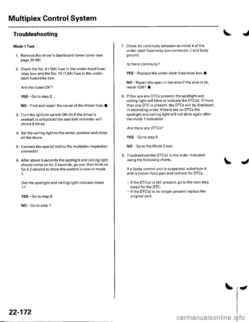
Troubleshooting
Mode 1 Tset
1. Remove the driver's dashboard lower cover {see
page 20-59).
2. Check the No. 9 ( 10A) fuse in the under-hood fuse/
relay box and the No. 10 (7.5A) fuse in the under-
dash fuse/relay box.
Are the fuses OK?
YES-Go to step 2.
NO-Find and repairthe cause ofthe blown fuse.!
3. Turn the ignition switch ON (ll).lf the driver's
seatbelt is unbuckled the seat belt reminder will
chime 6 times.
4. Set the ceiling light to the center position and close
allthe doors.
5. Connect the specialtoolto the multiplex inspection
conneclor.
6. After about 5 seconds the spotlight and ceiling light
should come on for 2 seconds, go out, then blink on
for 0.2 second to show the system is now in mode
1.
Did the spotlight and ceiling light indicate mode
1?
YES-Go to step 8.
NO Go to step 7.
22-172
-
7. Check for continuity between terminal 4ofthe
under-dash fuse/relay box connector J and body
ground.
ls there continuity?
YES Replace the under-dash fuse/relay box.l
NO - Repair the open in the wire.lf the wire is ok,
repair G301.1
8. lf ther are any DTCS present, the spotlight and
ceiling light will blink to indicate the DTC(S). lf more
than one DTC is present, the DTCS will be displayed
in ascending order, lf there are no DTCS the
spotlight and ceiling light will not blink again after
the mode 1 indication.
Are there any DTCg?
YES Go to step 9.
NO Go to the Mode 2 test.
9. Troubleshoot the DTC(S) in the order indicated
using the following charts.
lf a faulty control unit is suspected, substitute it
with a known food part and recheck for DTCS,
. lf the DTC(s) isstill present. go to the next step
listed for the DTC.. lf the DTC(S) is no longer present replace the
original part.
Page 1006 of 1139
IMultiplex Control Unit Input Test
Remove the driver's dashboard lower cover (see page 20-59).
Disconnect the under-dash fuse/relay box connectors C, E, F, J, K, O, p, O, X and y.
NOTE: All connectors are wire side of female terminals.
CONNECTOR C {14P}CONNECTOR E I13P)
1.
2.
CONNECTOR F {12P}
GRN/RED {USAIGRN/ORN (Canada)
coNNECTOR P (18P)
CONNECTOR J {8PI
WHT/RED
123
4561
BLK
{cont'd)
GRN/ORN BLU
CONNECTOR K {17P)
I
CONNECTOR O I12P)
CONNECTOR X {8P)CONNECTOR O (8P}
LT GRN/RED GRN/ORN
CONNECTOR Y {13P)
BRN/YEL
BLU/REDBLU/RED
345
67E10 )./12
YELGRN/RED
12457
810/V,/ l,/
WHT/GBN
3567I
,/1,/l,/121517
REDGRN/RED
WHT/BLK
RED/WHT
23,/1,/
618r012
BLK
22-175
Page 1012 of 1139

Seat Belts
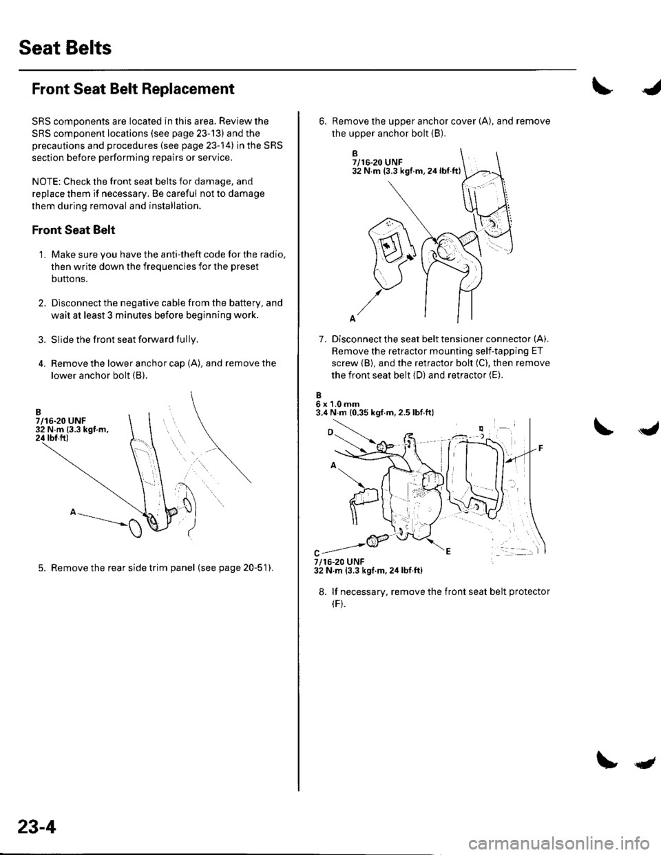
Front Seat Belt Replacement
SRS comDonents are located in this area. Review the
SRS component locations (see page 23-13) and the
precautions and procedures (see page 23-14) in the SRS
section before performing repairs or service,
NOTE: Check the front seat belts for damage, and
replace them if necessary. Be careful not to damage
them during removal and installation.
Front Seat Belt
Make sure you have the anti-theft code for the radio,
then write down the frequencies for the preset
buttons.
Disconnect the negative cable from the battery, and
wait at least 3 minutes before beginning work.
Slide the front seat forward fully.
Remove the lower anchor cap (A), and remove the
lower anchor bolt (B).
3.
1.
5. Remove the rear side trim panel (seepage20-51).
23-4
qt
B7/16-20 UNF32 N m (3.3 kgf.m,24lbt.ft)
7. Disconnect the seat belt tensioner connector (A).
Remove the retractor mounting self-tapping ET
screw {B), and the retractor bolt (C), then remove
the front seat belt (D) and retractor (E).
6x1.0mm3.4 N m {0.35 kgf.m,2.5 lbf.ft)
6. Remove the upper anchor cover {A), and remove
the upper anchor bolt (B).
7/16-20 UNF32 N.m (3.3 kgf m,2ir lbf.ft)
8. lf necessary, remove the
(F).
front seat belt protecto
Page 1121 of 1139

sRs
Front Passenger's Airbag Replacement
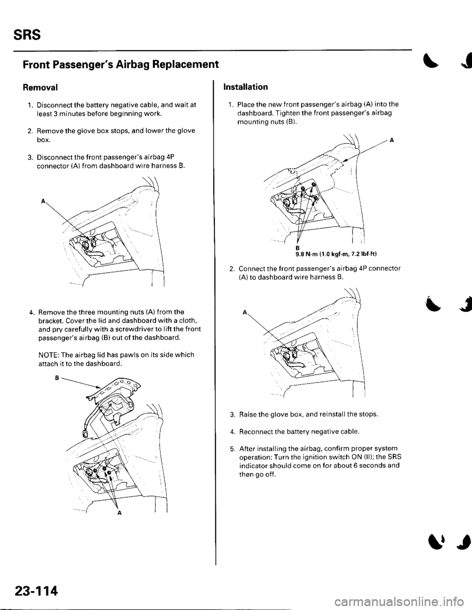
Removal
1. Disconnectthe battery negative cable, and wait at
least 3 minutes before beginning work,
2. Remove the glove box stops, and lower the glove
box.
3. Disconnect the front passenger's airbag 4P
connector (A) from dashboard wire harness B.
Remove the three mounting nuts (A) from the
bracket. Cover the lid and dashboard with a cloth,
and pry carefully with a screwdriver to lift the front
passenger's airbag (B) out ofthe dashboard.
NOTE:The airbag lid has pawls on its side which
4.
aftach it to the dashboard.
23-114
trr
Installation
1. Place the new front passenger's airbag (A) into the
dashboard. Tighten the front passenger's airbag
mounting nuts (B).
9.8 N m {1.0 kgf.m,7.2lbf ft}
Connect the front passenger's airbag 4P connector
(A)to dashboard wire harness B.
Raise the glove box, and reinstall the stops.
Reconnect the battery negative cable.
After installing the airbag, confirm proper system
operation; Turn the ignition switch ON (ll); the SRS
indicator should come on for about 6 seconds and
then go off.
L
4.
Page 1126 of 1139
)
3.
4.
Cable Reel Replacement
Removal
1. Make sure the front wheels are aligned straight
ahead.
Disconnect the battery negative cable, and wait at
least 3 minutes.
Remove the driver's airbag {see page 23-113).
Disconnect the connector (Al from the cruise
control sevresume switch, then remove the
steering wheel bolt (B).
Align the front wheels straight ahead, then remove
the steering wheel with a steering wheel puller (see
step 3 on page '17-6).
Do not tap on the steering wheel or steering
column shaftwhen removing the steering wheel.
)
5.
I,
6. Remove the dashboard lower cover (Ai.
Remove the column cover screws (A), then remove
the column covers (8, C).
7.
(cont'd)
23-119
Page 1129 of 1139

sRs
SRS Unit Replacement
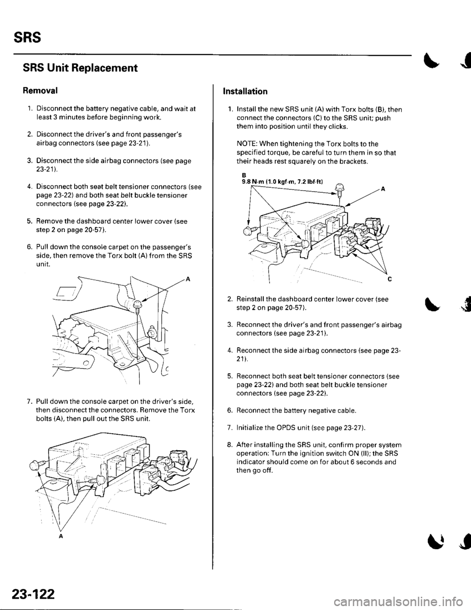
Removal
'1. Disconnect the battery negative cable, and wait at
least 3 minutes before beginning work.
2. Disconnect the driver's and front passenger's
airbag connectors (see page 23-21).
3. Disconnectthe side airbag connectors (see page
23-211.
4.Disconnect both seat belt tensioner connectors (see
page 23-22) and both seat belt buckle tensioner
connectors {see page 23-221.
Remove the dashboard center lower cover (see
step 2 on page 20-57).
Pull down the console carpet on the passenger's
side, then remove the Torx bolt (A)from the SRS
unit.
7. Pull down the console carpet on the driver's side,
then disconnect the connectors. Remove the Torx
bolts (A), then pull out the SRS unit.
23-122
lnstallation
1, Installthe new SRS unit (A)with Torx bolts (B), then
connect the connectors {C) to the SRS uniu push
them into position until they clicks.
NOTE: When tightening the Torx bolts to the
specified torque, be careful to turn them in so that
their heads rest squarely on the brackets.
Reinstall the dashboard center lower cover (see
step 2 on page 20-57).
Reconnect the driver's and front passenger's airbag
connectors (see page 23-21]'.
Reconnect the side airbag connectors (see page 23-
211.
Reconnect both seat belt tensioner connectors (see
page 23-221 and both seat belt buckle tensioner
connectors (see page 23-22).
Reconnect the battery negative cable.
Initialize the OPDS unit (see page 23'27).
After installing the SRS unit, confirm proper system
operation: Turn the ignition switch ON (ll); the SRS
indicator should come on for about 6 seconds and
then go off.
4.
6.
8.
7.
9.8 N.m (1.0 kgf m, 7.2 lbf ft)