Page 556 of 1139
12. lnstallthe EPS wire harness bracket (A) on the
gearbox housing, and connect the 6P connector (B)
propefly.
9.8 N.m{1.0 kgt m,7.2 lbt.ftl
13. Installthe heat shield (A).
,.!,..''6f
14.
15.
Center the steering rack within its stroke.
Wipe off any grease contamination from lhe ball
joint tapered section and threads. Then reconnect
the tie-rod ends 1A)to the damper steering arms.
lnstall the ball joint nut (B) and tighten them.
Install the new cotter pins (C), and bend them as
shown.
(cont'd)
B10 x 1.25 mmi€ N.m{4.4 kgf.m.32 tbt.ftl
to.
, -', ''l
:1)
17-65
Page 558 of 1139

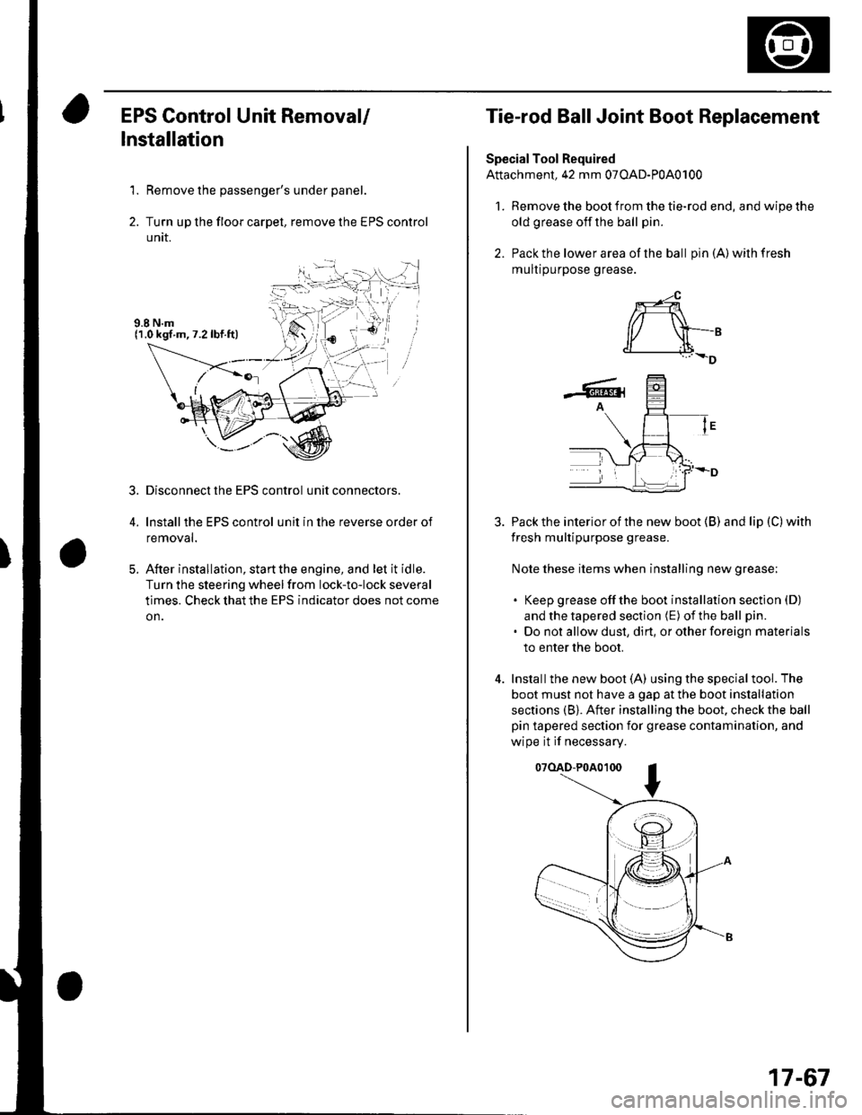
EPS Control Unit Removal/
Installation
1. Remove the passenger's under panel.
2. Turn up the floor carpel, remove lhe EPS control
untr.
Disconnect the EPS control unit connectors.
lnstallthe EPS control unit in the reverse order of
removal.
After installation, start the engine, and let it idle.
Turn the steering wheelfrom lock-to-lock several
times. Check that the EPS indicator does not come
on.
3.
E
Tie-rod Ball Joint Boot Replacement
Special Tool Required
Attachment, 42 mm 07OAD-P0A0100
l. Remove the boot from the tie-rod end, and wipe the
old grease off the ball pin.
2. Pack the lower area of the ball pin(A)wilhfresh
mulr purpose grease.
3. Pack the interior of the new boot (B) and lip (C) with
fresh multipurpose grease.
Note these items when installing new grease;
. Keep grease offthe boot installation section (D)
and the tapered section (E) of the ball pin.
. Do not allow dust, dirt, or other foreign materials
to enter the boot.
4. Installthe new boot (A) using the specialtool. The
boot must not have a gap at the boot installation
sections (B). After installing the boot. check the ball
pin tapered section for grease contamination, and
wipe it if necessary.
07(lAD-P0A0100
*-4
r/ \-,d______i.l+_D
-6rA
17-67
Page 579 of 1139
Special Tools Required
Ball joint remover,28 mm 07MAC-S100200
Removal
1. Raise the front of the vehicle, and support it with
safety stands in the proper location (see page 1-8).
Remove the front wheels.
Remove the cotter pin (A) from the tie-rod end ball
ioint, and remove the nut (B).
10 mm HEX NUT
07MAC-S1002000
Disconnectthe tie-rod end from the steering arm
on the damper using the specialtool (see page 18-
10 ).
Remove the bolts, and remove the wheel sensor
harness bracket {A) and brake hose bracket (B)
from the damper. Do not disconnect the wheel
4.
sensor connector.
A6x1.0mm
/.8
x 1.25 nm
q
5. Remove the damper pinch bolts (A)while holding
the nuts (B).
6. Remove the flange nuts (A)from the top ofthe
damper,
A10 x 'l.25 mm
7. Lower the lower arm, and remove the damper
assembly (B).
(cont'd)
18-21
Page 586 of 1139

Rear Suspension
Hub Bearing Unit Replacement
(cont'd)
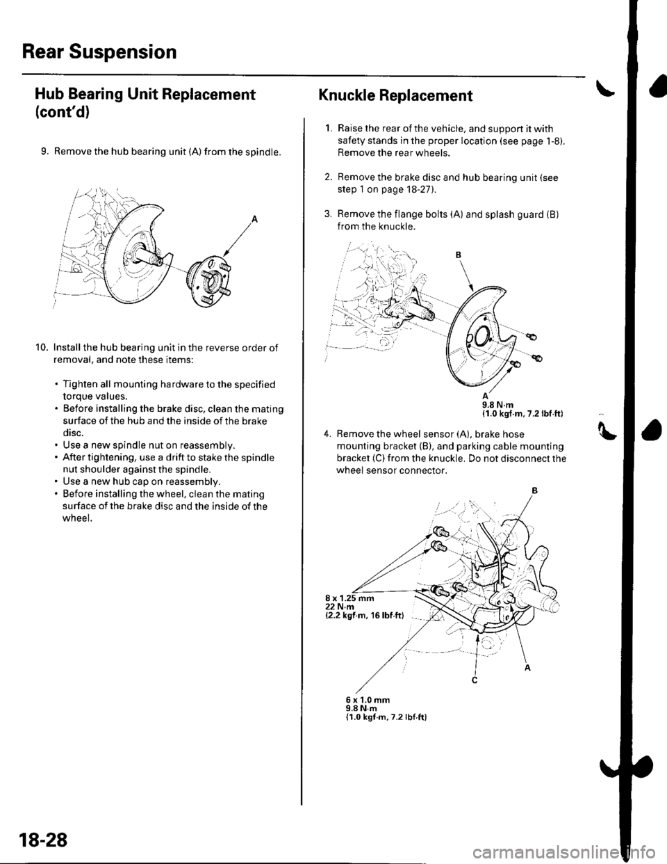
9. Remove the hub bearing unit (A) from the spindle.
Install the hub bearing unit in the reverse order of
removal, and note these items:
. Tighten all mounting hardware to the specified
torque values,. Before installing the brake disc, clean the mating
surface ot the hub and the inside of the brake
disc.. Use a new spindle nut on reassembly.. After tightening, use a drift to stake the spindle
nut shoulder against the spindle.. Use a new hub cap on reassembly.. Before installing the wheel, clean the mating
surface of the brake disc and the inside of the
wneel.
10.
,=,,,
18-28
Raise the rear of the vehicle, and suppon it with
safety stands in the proper location (see page 1-8).
Remove the rear wheels.
Remove the brake disc and hub bearing unit (see
step 1 on page 18-27).
Remove the flange bolts (A) and splash guard (B)
from the knuckle.
11.0 kgf.m, 7.2 lbf ft)
4. Remove the wheel sensor(A), braKe nose
mounting bracket (B), and parking cable mounting
bracket (C) from the knuckle. Do not disconnect the
wheel sensor connector.
8 x 1.25 mm22 N.m{2.2 kgf m, 16 lbf ftl
Knuckle Replacement
1.
6x1.0mm9.8 N,m{I.0 kgt.m,7.2 lbf ft)
tt
Page 601 of 1139

Conventional Brake Components
Brake Pedaland Brake PedalPosition Switch Adjustment
Pedal Height
1.Disconnect the brake pedal position switch
connector, turn the brake pedal position switch (A)
counterclockwise, and pull it back until it is no
longer touching the brake pedal.
Lift up the carpet and the insulator cutout (B).
l\4easure the pedal height (C) from the middle of
the left side of the pedal pad (D).
Standard Pedal Height (with carpet removed):
184 mm (7 4/16 in.)
Loosen the pushrod locknut (A), and screw the
pushrod in or out with pliers until the standard
pedal height from the floor is reached. After
adjustment, tighten the locknut firmly. Do not
adjust the pedal height with the pushrod pressed.
15 N.m(1.5 kgl m. 11 lbl ft)
19-6
7. Check the brake pedal free play as described below.
Pedal Free Play
4. With the engine off, inspect the play (A) on the
pedal pad (B) by pushing the pedal by hand.
Free Play: 0.4- 3.0 mm {0.016 0.'l18in.)
lf the pedal free play is out of specification, adjust
the brake pedal position switch (C). lf the pedal free
play is insufficient, it may result in brake drag.
Push in the brake oedal oosition switch until its
plunger is fully pressed (threaded end (A)touching
the pad (B) on the pedal arm). Then, turn the switch
45" clockwise to lock it. The gap between the brake
pedal position switch and the pad is automatically
adjusted to 0.4 to 3.0 mm (0.016 0.118 in.) by
locking the switch. Make sure the brake lights go
otf when the pedal is released.
t
6.
Page 605 of 1139
Conventional Brake Components
Parking Brake Switch Test
1. Remove the rear console, and disconnect theconnector (A)from the switch (B).
Check for continuity between the switch terminal
and body ground:
. With the brake lever up, there should be
continuity.. With the brake lever down, there should be no
continuity.
R
'dFu\!E!UF-
Y
19-10
Brake Fluid Level Switch Test
Check for continuity between the terminals (A) with thefloat in the down position and the up position.
. Remove the brake fluid completely from the reservoir.
With the float down, there should be continuity.. Fjllthe reservoir with brakefluidto MAX(upper) level(B). With the float up, there should be no continuity.
\
Page 610 of 1139

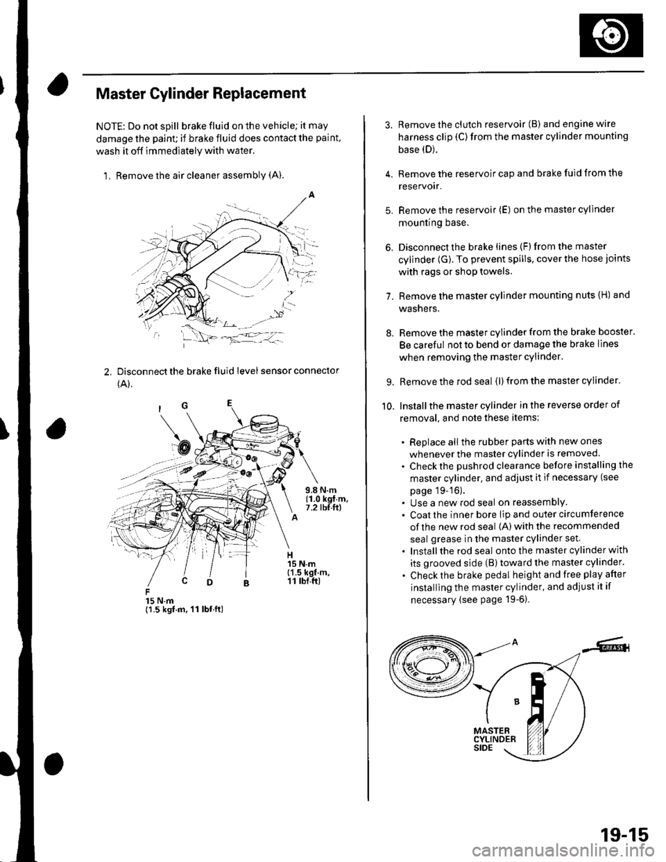
Master Cylinder Replacement
NOTE: Do not spill brake fluid on the vehicle; it may
damage the paint; if brake fluid does contact the paint,
wash it off immediately with water,
1, Remove the air cleaner assembly (A).
2, Disconnect the brake fluid level sensor connector
(A).
15 N.m{1.5 kgt.m, 11 lbt.ft)
3. Remove the clutch reservoir (B) andenginewire
harness clip (C)from the master cylinder mounting
base (D).
4. Remove the reservoir cap and brake fuid from the
reservoir.
5. Remove the reservoir (E) on the master cylinder
mountrng Dase.
6, Disconnect the brake lines (F)from the master
cylinder (G). To prevent spills, cover the hose joints
with rags or shop towels.
7. Remove the master cylinder mounting nuts {H) and
washers.
8. Remove the master cylinder from the brake booster.
Be careful not to bend or damage the brake lines
when removing the master cylinder.
9. Remove the rod seal (l) from the master cylinder.
10. Installthe master cylinder in the reverse order of
removal, and note these items:
. Replace all the rubber parts with new ones
whenever the master cylinder is removed.
. Check the pushrod clearance before installing the
master cylinder. and adjust it if necessary (see
page 19-16).. Use a new rod seal on reassemblY. Coat the inner bore lip and outer circumference
of the new rod seal {A) with the recommended
seal grease in the master cylinder set.
. Installthe rod seal ontothe master cylinder with
its grooved side (B)toward the master cylinder.
. Check the brake pedal height and free play after
installing the master cylinder, and adjust it if
necessary (see page 19-6).
19-15
Page 624 of 1139
ABS Gomponents
(Component Location Index
UNDER.HOOD FUSE/RELAY BOX
RIGHT-REAR WHEEL SENSORInspection, page 19-59Replacement, page 19-59UNDER.OASH FUSE/RELAY BOX
\L
LEFT.REARWHEEL SENSORInspection, page 19-59Replacement, page 19-59
DATA LINK CONNECTOR I16PIRIGHT.FRONT WHEEL SENSORInspection, page 19-59Replacement, page 19-59
ABS MODULATOR.CONTROL UNITRemoval and Installation, page 19'57LEFT-FRONT WHEEL SENSORInspection, page 19-59Replacement, page 19 59
19-30