2003 HONDA CIVIC Ignition switch
[x] Cancel search: Ignition switchPage 1007 of 1139
Multiplex Control System
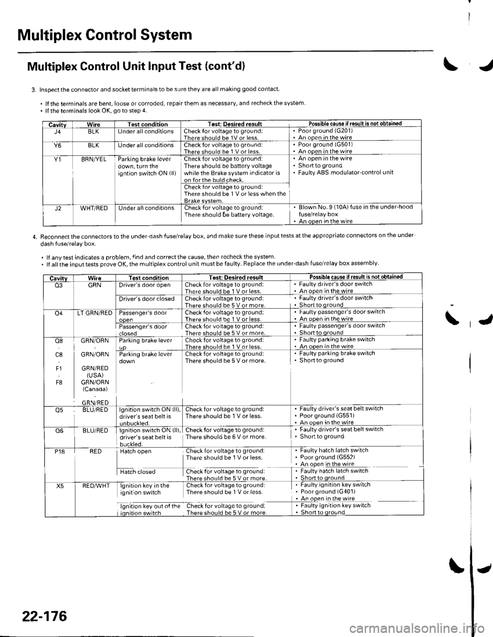
Multiplex Control Unit lnput Test (cont'd)
3. Inspect the connector and socket terminals to be sure they are all making good contact
.lftheterminalsarebent,looseorcorroded,repairthemasnecessary,andrecheckthesystem. llthe terminals look OK, go to step 4.
4. Reconnectthe connectorstothe under dash fuserelay box, and make surethese inputtests atthe appropriate connectors on lhe under-
dash fuse/relav box.
. lf any test indicates a problem, {ind and correct the cause, then recheck the system. lf allthe input tests prove OK, the multiplex control unit must be faulty. Replace the under_dash fuse/relay box assembly
CavitvWireTest conditionTest: Desired .esult r Possible cause if resullE qS!q!!e!!ed
J4BLK[J nder all conditionsCheck {or voltage 1o ground:Therc sholl.l he 1V or lessPoor ground (G20'l)An ooen in the wire
Y6BLKlJnder all conditionsCheck for voltage to ground:There should bc 1 V or less.Poor ground 1G501)An ooen in the wire
Y1BFNryELParking brake leverdown, turn theigntion switch ON (ll)
Check for voltage to ground:There should be battery voltagewhile the Brake system indicator ison forthe buld check.
An open in the wireShortto groundFaulty ABS modulatorcontrol unit
Check for voltage to ground:There should be 1V or less when the
J2WHT/REDUnder allconditionsCheck for voltage to groundiThere should be baftery voltage.Blown No.9 (10A)fuse in the under'hoodfuse/relay boxAn oncn in rhc wire
CavitvTest conditionTesi: Oesired resultPossible cause ifresult is notobtained
o3GRNDriver's door openCheck for voltage to ground:There should be 1 V or less-Faulty driver's door switchAn ooen in the wire
Driver's door closedCheck for voltage to ground:There should be 5 V or more.Faulty driver's door switchShort to qround
O4LT GRN/REDPassenger's doorCheck .for voltage 10 ground:There should be 1 V or less.Faulty passenger's door switchAn ooen inthewire
Passenger's doorCheck for voltage to ground:There should be 5 V or more.Faulty passenger's door switchShort to oround
osI]l.l
4.,
F1
F8
GRN/ORN
GRN/ORN
GRN/RED(USA)GRN/ORN(Canada)
Parking brake leverCheck for voltage to groLrnd:There shorl.l be 1 V or less.Faulty parking brake switch. An ooen in thewireCheck for voltage to ground:There should be 5 V or more.
. Faulty parking brake switchShortto ground
o5BLU/REDlgnition switch ON (ll),
driver's seat belt isCheck for voltage to ground:There should be 1V or less.Faulty driver's seat belt switchPoorground (G551)An oDen in the wire
Q6BLU/REDlgnition switch ON (ll)
driver's seat belt isbuckled.
Check {or voltage to ground:There should be 6 V or more.Faulty driver's seat belt switchShortto ground
P18RED
H",=
Check for voltage to ground:There sho0ld be 1V or less-
f -9*:li:'^:**:':s*:*
Faulty hatch latch swrtchPoor ground (G552)An open in the wireFaulty hatch latch switch
X5lgnirion key in the Check for voliage to gtound:ignit on switch Thpre should be I V or lcss
lgnrtron kev our o{ the Check for vollage to ground:
. Faulty ignition key switch. Poor ground (G401). An open in the wire
I : [11y.'::i':::1"' **6
\
22-176
Page 1008 of 1139
IJ
IJ
IJ
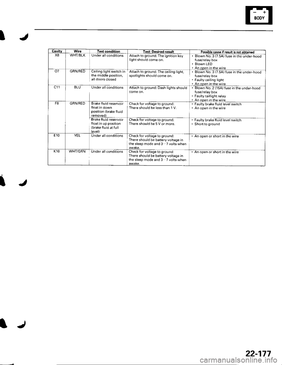
CavitvWireTest conditionTest: Desired resultPossible cause if resuk is not obtainedX8WHT/BLKUnder allconditionsAttach to ground:The ignition keylight should come on.Blown No.3 (7.5A)fuse in the under,hood
Blown LEDAn ooen in the wireo7GRN/REDCeiling light switch inthe middle position,all doors closed
Attach to ground:The ceiling light,spotlights should come on.Elown No. 3 (7.54)fuse in the undeFhood
Faulty ceiling lightAn oDen in the wirec]1BLU Under all conditionsAttach to ground: Dash lights shouldBlown No. 2 (15Aifuse in the under-hoodfuse/relay boxFaulty taillight relayAn ooen in the wireF8GRN/REDBrake fluid reservoirfloat in downposition (brake fluid
Check for voltage to ground:There should be less than I V.Faulty brake fluid level switchAn open in the wire
Brake lluid reservoirfloat in up position(brake fluid at fulllevel)
Check for voltage to ground:There should be 5 V or more.Faulty brake fluid level switchShortto ground
E10YELUnder all conditionsCheck for voltage to ground:There should be battery voltage inthe sleep mode and 3 Tvoltswhen
. An open or short in the wire
K10WHT/GRNUnder all conditionsCheck for voltage to ground:There should be battery voltage inthe sleep mode and 3 Tvoltswhen
An open or short in the wire
22-177
Page 1021 of 1139
sRs
Precautions and Procedures
General Precautions
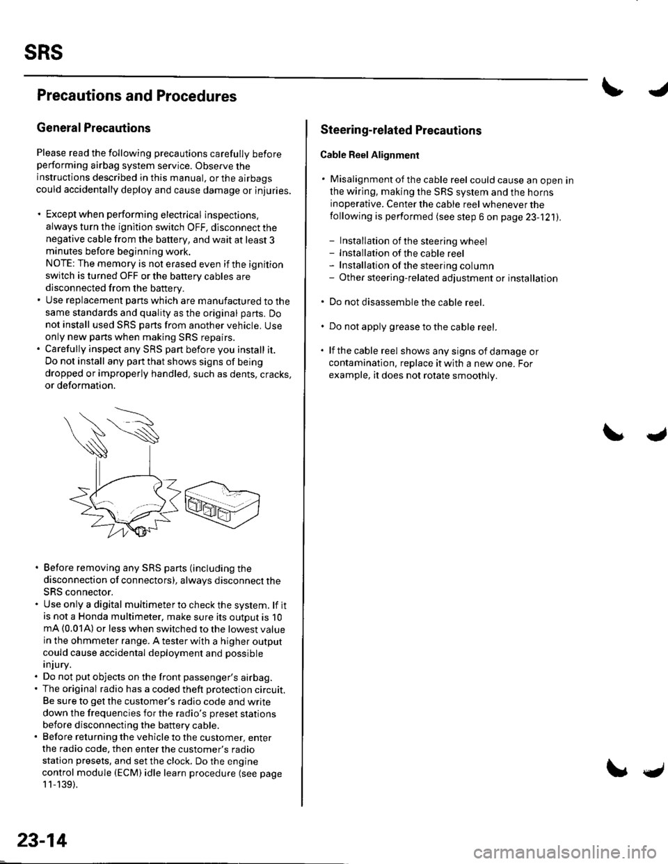
Please read the following precautions carefully beforeperforming airbag system service. Observe theinstructions described in this manual. or the airbags
could accidentally deploy and cause damage or injuries.
. Except when performing electrical inspections.
always turn the ignition switch OFF, disconnect the
negative cable from the battery, and wait at least 3minutes before beginning work.
NOTE: The memory is not erased even if the ignition
switch is turned OFF or the battery cables are
disconnected from the battery.. Use replacement pans which are manufactured to the
same standards and quality as the original parts. Do
not install used SRS parts from another vehicle. Useonly new pans when making SRS repairs.. Carefully inspect any SRS part before you install it.
Do not install any part that shows signs of being
dropped or improperly handled, such as dents, cracks,
or deformation.
. Before removing any SRS parts (including the
disconnection of connectors), always disconnect the
SRS connector.. Use only a digital multimeter to check the system. lf itis not a Honda multimeter, make sure its outout is 10mA (0.01A) or less when switched to the lowest value
in the ohmmeter range. A tester with a higher output
could cause accidental deployment and possible
injury.. Do not put objects on the front passenger's airbag.. The original radio has a coded theft protection circuit.
Be sure to get the customer's radio code and write
down the frequencies for the radio's preset stations
before disconnecting the battery cable.. Before returning the vehicle to the customer, enter
the radio code. then enter the customer's radio
station presets, and set the clock. Do the engine
control module (ECM) idle learn procedure (see page
11-139).
23-14
c
Steering-related Plecautions
Cable Reel Alignment
. Misalignment of the cable reel could cause an open in
the wiring, making the SRS system and the horns
inoperative. Center the cable reel whenever the
following is performed (see step 6 on page 23-121).
- Installation of the steering wheel- Installation of the cable reel- Installation ofthe steering column- Other steering-related adjustment or installation
. Do not disassemble the cable reel.
. Do not apply grease to the cable reel.
. lf the cable reel shows any signs of damage or
contamination. replace it with a new one. For
example, it does not rotate smoothly.
Page 1023 of 1139
sRs
Precautions and Procedures {cont'dl
SRS Unit, Front lmpact Sensors, and Side
lmpact Sensors
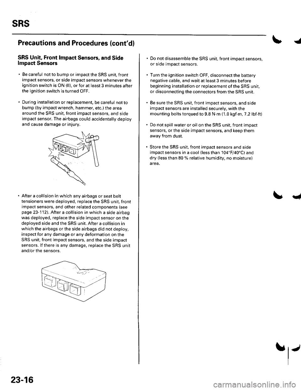
. Be careful not to bump or impact the SRS unit, front
impact sensors, or side impact sensors whenever the
ignition switch is ON (ll), or for at least 3 minules after
the ignition switch is turned OFF.
. During installation orreplacement, be careful notto
bump (by impact wrench, hammer, etc.) the area
around the SRS unit, front impact sensors, and sjde
impact sensor. The airbags could accidentally deploy
and cause damage or injury.
After a collision in which any airbags or seat belt
tensioners were deployed. replace the SRS unit, front
impact sensors, and other related components (see
page 23-112). After a collision in which a side airbag
was deployed. replace the side impact sensor on the
deployed side and the SRS unit. After a collision in
which the airbags or the side airbags did not deploy,
inspect for any damage or any deformation on the
SRS unit, front impact sensors, and the side impact
sensors. lf there is any damage, replace the SRS unit
and/or the sensors.
23-16
.j
. Do not disassemble the SRS unit, front impact sensors,
or side impact sensors.
. Turn the ignition switch OFF, disconnect the battery
negative cable, and wait at least 3 minules before
beginning installation or replacement of the SBS unit,
or disconnecting the connectors from the SRS unit.
. Be sure the SRS unit, front impact sensors, and side
impact sensors are installed securely. with the
mounting bolts torqued to 9.8 N.m (1.0 kgf.m,7.2 lbf.ft)
. Do not spill wateroroil on the SRS unit, front impact
sensors, or the side impact sensors, and keep them
away from dust.
. Store the SRS unit, front imDact sensors and side
impact sensors in a cool (less than 104"F/40'C) and
dry (less than 80 % relative humidity, no moisture)
area.
I
Page 1027 of 1139
sRs
Precautions and Procedures (cont'dl
Disconnecting System Connectors
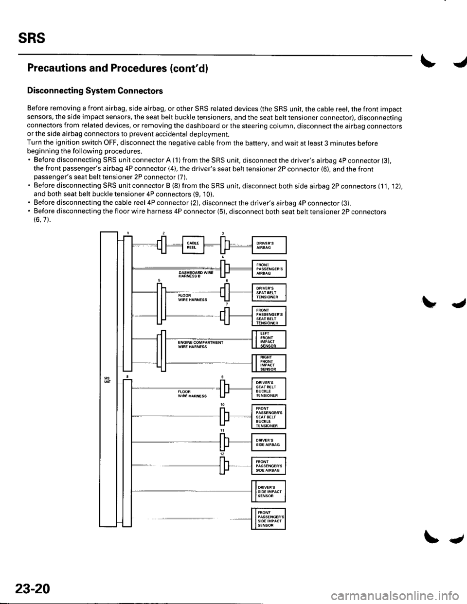
Before removing a front airbag. side airbag, or other SRS related devices {the SRS unit, the cable reel, the front impact
sensors, the side impact sensors, the seat belt buckle tensioners, and the seat belt tensioner connector), disconnectingconnectors from related devices, or removing the dashboard or the steering column, disconnect the airbag connectorsor the side airbag connectors to prevent accidental deploVment.
Turn the ignition switch OFF, disconnect the negative cable from the battery, and wait at least 3 minutes before
beginning the following procedures.'BeforedisconnectingSRSunitconnectorA(1)fromtheSRSunit,disconnectthedriver'sairbag4Pconnector(3).
the front passenger's airbag 4P connector (4), the driver's seat belt tensioner 2P connector (6), and the frontpassenger's seat belt tensioner 2P connector (7).
. Before disconnecting SRS unit connector B (8) from the SRS unit, disconnect both side airbag 2P connectors (11. '12),
and both seat belt buckle tensioner 4P connectors (9, 10).. Before disconnecting the cable reel 4P connector (2), disconnect the driver's airbag 4P connector (3).'Beforedisconnectingthefloorwireharness4Pconnector(5),disconnectbothseatbelttensioner2Pconnectors
(6.7).
23-20
\.
Page 1030 of 1139
General Troubleshooting Information
DTC (Diagnostic Trouble Codesl
The self-diagnostic function of the SRS system allows it
to locate the causes of system problems and then store
this information in memory. For easier troubleshooting,
this data can be retrieved via a data link circuit.
. When you turn the ignition switch ON (ll), the SRS
indicator will come on. lf it goes off after 6 seconds,
the system is normal.. lf there is an abnormality, the svstem locates and
defines the problem, stores this information in
memory, and turns the SRS indicator on. The data
will remain in the memory even when the ignition
switch is turned off or if the battery is disconnected.. When you connect the Honda PG lM Tester to the 16P
data link connector (DLC)to short the SCS terminal,
and turn the ignition switch ON (ll). the SRS indicator
will indicate the diagnostic trouble code (DTC) by the
number of blinks.. When you connect the Honda PGM Tester to the 16P
data link Connector (DLC), you can retrieve the DTC in
the Honda Systems "SRS" menu.. After reading and recording the DTC, proceed with
the troubleshooting procedure for th is code.
Precautions. Use only a digital multimeter to check the system. lf
it's not a Honda multimeter, make sure its output is
10 mA (0.01A) or less when switched to the smallest
value in the ohmmeter range, A tester with a higher
output could damage the airbag circuit or cause
accidental airbag deployment and possible injury.. Whenever the ignition switch is ON (ll), or has been
turned OFF for less than 3 minutes, be careful not to
bump the SRS uniU the airbags could accidentally
deploy and cause damage or injuries.. Before you remove the SRS harness, disconnect the
driver's airbag connector. the front passenger's
airbag connector, both side airbag connectors, both
seat belt buckle tensioner connectors, and both seat
belt tensioner connectors.. Make sure the battery is sufficiently charged. lf the
battery is dead or low, measuring values won't be
correct.. Do not touch a tester probe to the terminals in the
SRS unit or harness connectors, and do not connect
the terminals with a jumper wire. Use only the
backprobe set and the Honda PGM Tester. Backprobe
spring loaded lock type connectors correctly.
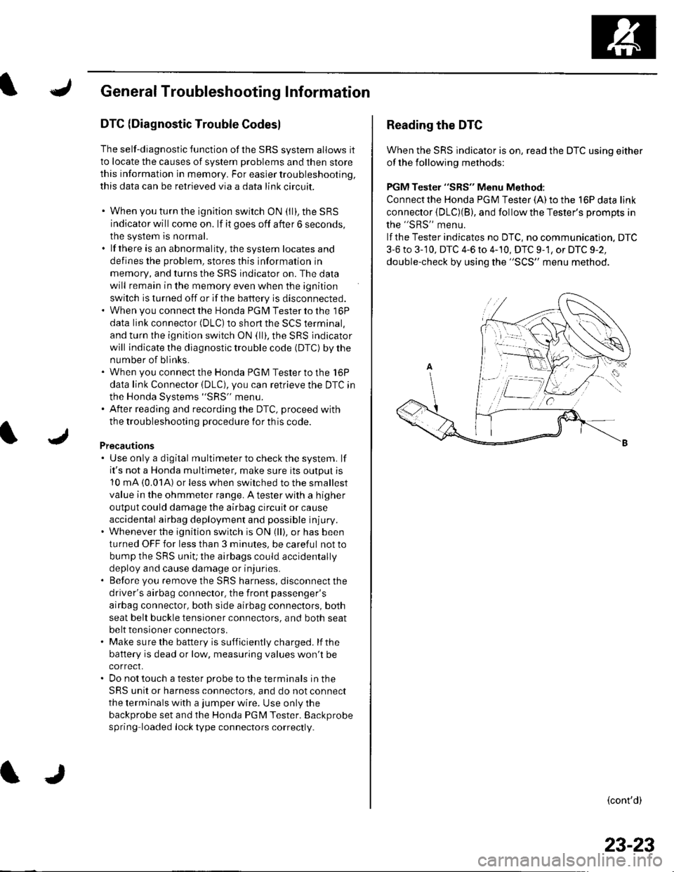
Reading the DTC
When the SRS indicator is on, read the DTC using either
of the following methods:
PGM Tester "SRS" Menu Method:
Connect the Honda PGM Tester {A) to the 16P data link
connector {DLC)(B), and follow the Tester's Drompts in
the "SRS" menu.
lf the Tester indicates no DTC, no communication. DTC
3-6 to 3-'10, DTC 4-6 to 4-10, DTC 9-1, or DTC 9-2,
double-check by using the "SCS" menu method.
(cont'd)
23-23
Page 1031 of 1139
sRs
General Troubleshooting Information (cont'd)
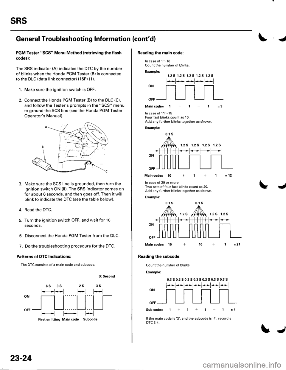
PGM Tester "SCS" Menu Method {retrieving the flash
codes):
The SRS indicator (A) indicates the DTC by lhe number
of blinks when the Honda PGM Tester (B) is connected
to the DLC (data link connector) ( 16P) (1).
'1. Make sure the ionition switch is OFF.
2. Connect the Honda PGN4 Tester (B) to the DLC (C),
and follow the Tester's oromDts in the "SCS" menu
to ground the SCS line (see the Honda PGM Tester
ODerator's Manual).
Make sure the SCS line is grounded, then turn the
ignition switch ON (ll). The SRS indicator comes on
for about 6 seconds, and then goes off. Then it will
blink to indicate the DTC (see the table below).
Read the DTC.
Turn the ignition switch OFF, and wait for 10
seconds.
3.
4.
5.
6, Disconnect the Honda PGM Tester from the DLC.
7. Do the troubleshooting procedure for the DTC.
Patteins of DTC Indications:
The DTC consists of a main code and subcode.
S: Second
25 356S
oN
[ltl|[
oFFl I l------Ll---l I
First emitting Main code Subcode
23-24
\J
Reading the main code:
In case of 1- 10Count the number of blinks.
Examplo:1.2 S r.2 S 1.2 S 1.2 S 1.2 S
*t**t*l*l
""_f]_flfl
Maincodo= 1 + 1 + 1 =3
In case ot 11..'15Four fast blinks count as 10.Add any funher blinks together as shown.
Example:
0.1 s
,A/// t\\//lii 1.rs r.2s r.2s 1.2s
_ | *t* -L'--*l
Main code= 10 I
ln case of 20 or moreTwo sets of four fast blinks count as 20.Add any funher blinks together as shown.
Examplo:
0.1 s 0.1s
,y'fl\,,. /[N 12s 12s
=12
L4
""ffi
*FtftffN*+fH-t-ff *l-
Main code= 10 + 10
Reading the subcode:
Count the number of blinks.
Example:
0.3 s 0.3 s 0.3 s 0.3 s 0.3 s 0.3 s 0.3 s
l**t**t*t*t*l
""ffi
Subcode=1+1+1r'1=4
lf the main code is '3', and the subcode is '4', record aDTC 3 4.
Page 1033 of 1139
sRs
General Troubleshooting Information (cont'dl
Erasing the DTG Memory
Specisl Tool Required
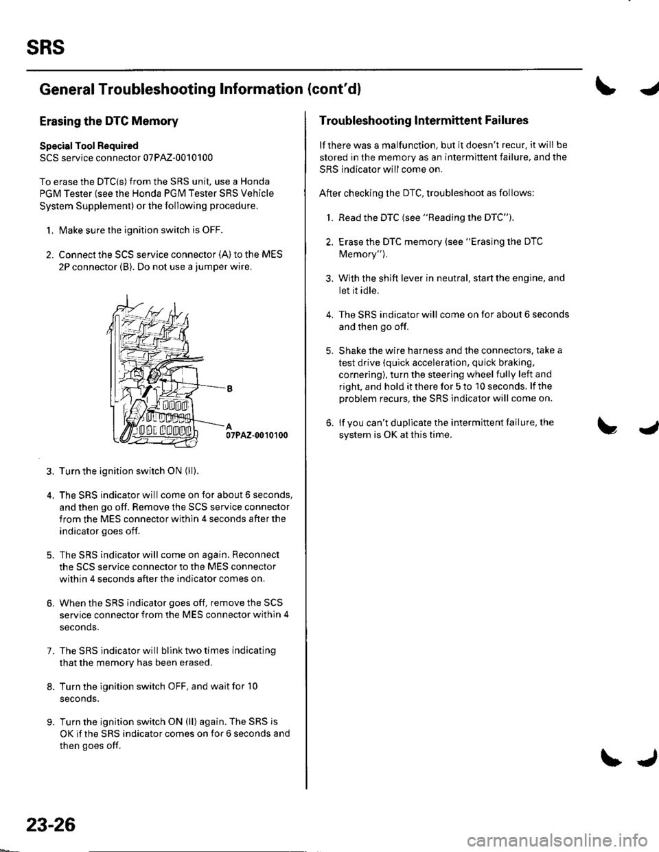
SCS service connector 07PAz-0010100
To erase the DTC(S)from the SRS unit, use a Honda
PGM Tester {see lhe Honda PGfM Tester SRS Vehicle
System Supplement) or the following procedure.
1. Make sure the ignition switch is OFF.
2. Connect the SCS service connector {A) to the MES
2P connector (B). Do not use a jumper wire.
07PAZ-0010100
3. Turn the ignition switch ON (ll).
4. The SRS indicator will come on for about 6 seconds,
and then go off. Remove the SCS service connector
from the MES connector within 4 seconds after the
indicator goes off.
5. The SRS indicator will come on again. Reconnect
the SCS service connector to the MES connector
within 4 seconds after the indicator comes on.
6. When the SRS indicator goes off, remove the SCS
service connector from the MES connector within 4
seconds.
7. The SRS indicator will bllnk two times indicating
that the memory has been erased.
8. Turn the ignition switch OFF, and wait for '10
seconds.
9. Turn the ignition switch ON (ll) again. The SRS js
OK if the SRS indicator comes on for 6 seconds and
then goes off.
23-26
\J
Troubleshooting lntermittent Failures
lf there was a malfunction, but it doesn't recur. it will be
stored in the memory as an intermittent failure, and the
SRS indicator will come on.
After checking the DTC, troubleshoot as follows:
1. Read the DTC (see "Reading the DTC").
2. Erase the DTC memory (see "Erasing the DTC
Memory").
3. With the shift lever in neutral, start the engine, and
let it idle.
The SRS indicator will come on for about 6 seconds
and then go off.
Shake the wire harness and the connectors. take a
test drive (quick acceleration, quick braking,
cornering), turn the steering wheel fully left and
right, and hold it there for 5 to '10 seconds. lf the
problem recurs, the SRS indicator will come on.
lf you can't duplicate the intermittent failure, the
system is OK at this time.
4.