Page 1034 of 1139
I
Initializing the OPDS {Occupant Position Detection System} Unit
Special Tool Required
SCS service connector 07PAz-00'1 01 00
When a seat-back cover, seat-back cushion, and/or OPDS unit is replaced, initialize the OPDS by following theprocedure below.
NOTE: Make sure the front passenger's seat is dry. Set the seat-back in the normal position, and make sure there isnothing on the seat.
'1. l\4ake sure the ignition switch is OFF.
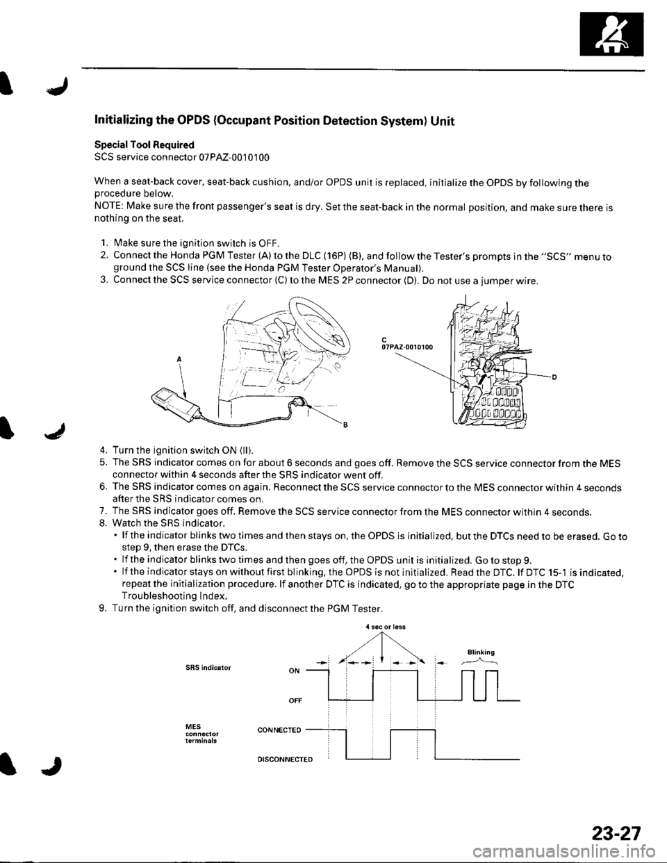
2. Connect the Honda PGM Tester (A) to the DLC (16P) (B), andfollowtheTester's prompts jn the ,,SCS,, menu toground the SCS line (see the Honda PGM Tester Operator's ManuaD.
3. Connect the SCS service connector (C) to the MES 2P connector (D). Do not use a iumoer wire.
c07PAZ-00r0100
4. Turn the ignition switch ON {ll).
5. The SRS indicator comes on for about 6 seconds and goes off. Remove the SCS service connector from the MESconnector within 4 seconds after the SRS indicator went off.
6. The SRS indicator comes on again. Reconnect the SCS service connector to the MES connector within 4 secondsafter the SRS indicator comes on.
7. The SRS indicator goes off. Remove the SCS service connector from the MES connector withln 4 seconds.8. Watch the sRS indicator.'lftheindicatorblinkstwotimesandthenstayson,theOPDSisinitialized.buttheDTCSneedtobeerased.Goto
step 9, then erase the DTCS..lftheindicatorblinkstwotimesandthengoesoff,theOPDSunitisinitialized.Gotostep9.
' lf the indicator stays on without first blinking.the OPDS is not initialized. Readthe DTC. lf DTC 15-'l is indicated,repeat the initialization procedure. lf another DTC is indicated, go to the appropriate page in the DTCTroubleshooting Index.
9. Turn the ignition switch off, and disconnect the PGM Tester.
SBS indic.ror
MES
IJ
DISCONNECTED
23-27
Page 1037 of 1139
SRS
SymptomDiagnostic procedureAlso check for
SRS indicator doesn't come onSRS Indicator Troubleshooting (see
paoe 23-105)
SRS indicator stays on when in"SCS" menu method
SRS Indicator Troubleshooting (see
step 1 on page 23-107)
Inability to retrieve DTCs with the
PGM Tester. Retrieve the flash
codes using the SCS menu method
(see page 23-24).
Slde airbag cutoff indicator stays
on after bulb check (lfthe
indicator stays on, it does not set
a DTC). Side airbag cutoff
indicator is flashing
. Make sure nothing is on the fronl
passenger's seat.. lf the side airbag cutoff indicator
stays on after the ignition switch
is turned ON (ll), initialize the
OPDS unit (see page 23-271.- lf the side airbag cutoff
indicator operates normallY, the
system is OK.- lf the side airbag cutoff
indicator stays on, replace the
uFU5 SenSOr {See SeCrOn ZUl.
The sensor is part of the seat-
back Dad.
DTC 15-2 troubleshooting
Symptom Troubleshooting Index\4
trJ
23-30
\J
Page 1040 of 1139
Self-diagnosis System
A self-diagnosis circuit is built into the SRS uniU when the ignition switch is turned ON (ll), the SRS indicator comes onand goes off after about 6 seconds if the SRS is operating normally.
lf the indicator does not come on, or does not go off after 6 seconds. or if il comes on while driving, it indicates anabnormality in the SRS. The SRS must be inspected and repaired as soon as possible.
For better serviceability, the SRS unit memory stores a DTC that relates to the cause of the malfunction, and the unit isconnected to the data link circuit. This information can be read with the Honda PGM Tester when it is connected to thedata link connector (DLc) (see page 23-23).
23-33
Page 1043 of 1139
sRs
J
a
DTC Troubleshooting
DTC 1-1: Open in Driver's Airbag Inflator
DTC 1-2: Increased Resistance in Driver's
Airbag Inflator
Special Tools Required. SRS inflator simulator 07SAZ-TB4011A. SRS simulator lead F 07XAZ-S230100
1. Erase the DTC memory (see page 23-26).
2. Turn the ignition switch ON {ll), and check that the
SRS indicator comes on for aboul 6 seconds and
then goes off.
Does the SBS indicator stay on?
YES-Go to step 3.
NO Intermittent failure, system is OK at this time.
Go to Troubleshooting Intermittent Failures (see
page 23-26).
3. Turn the ignition switch OFF. Disconnect the
battery negative cable, and wait for 3 minutes.
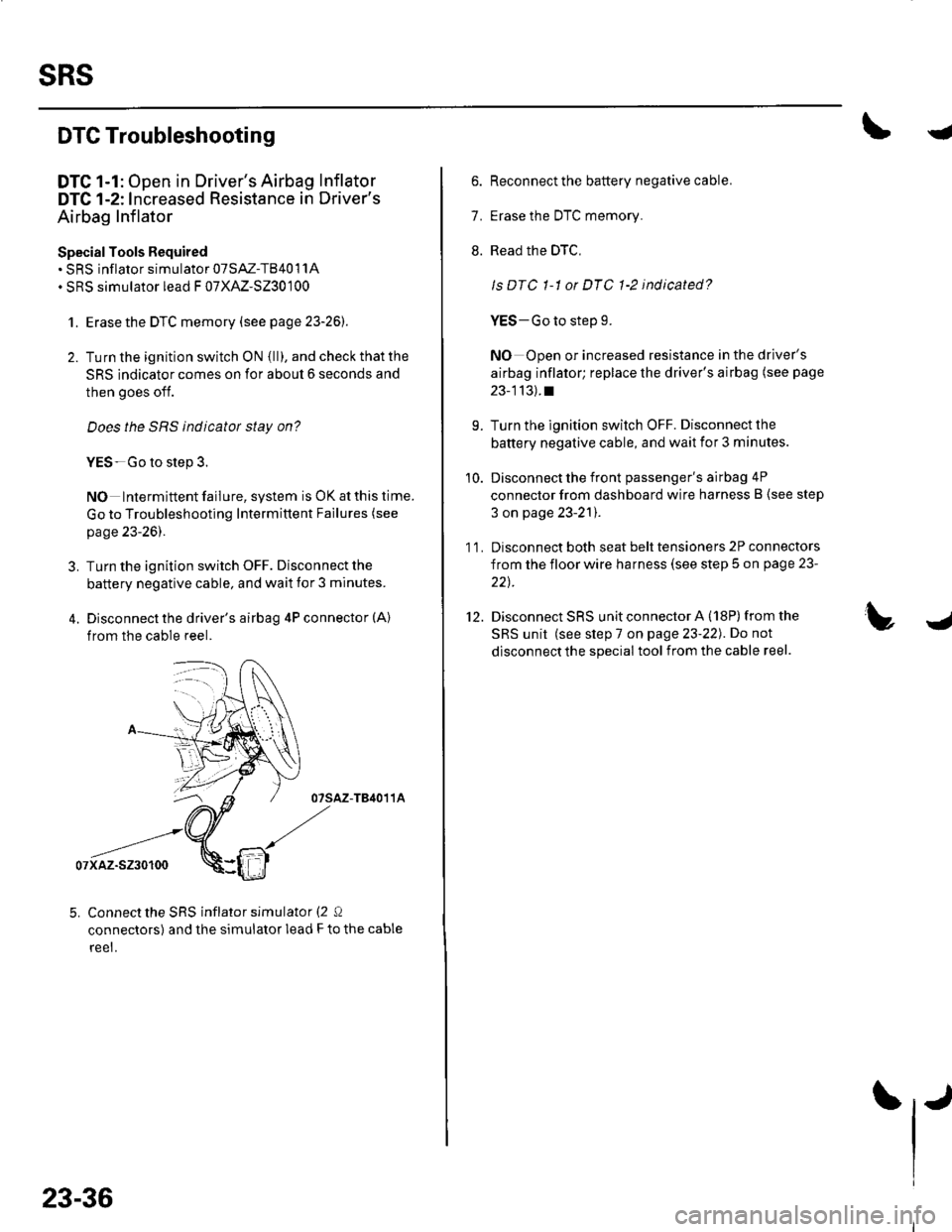
4. Disconnect the driver's airbag 4P connector (A)
from the cable reel.
07sAz-TB4011A
07xaz-s230100
5. Connect the SRS inflator simulator (2 Q
connectors) and the simulator lead F to the cable
reet.
23-36
6. Reconnect the battery negative cable.
7. Erase the DTC memory.
8. Read the DTC,
ls DTC 1-1 or DTC 1-2 indicated?
YES-Go to step 9.
NO Open or increased resistance in the driver's
airbag inflator; replace the driver's airbag (see page
23-113).t
9. Turn the ignition switch OFF. Disconnect the
battery negative cable, and wait ior 3 minutes.
10. Disconnect the front passenger's airbag 4P
connector from dashboard wire harness B (see step
3 on page 23-21).
1 1. Disconnect both seat belt tensioners 2P connectors
from the floor wire harness (see step 5 on page 23-
22t.
12. Disconnect SRS unit connector A (18P)from the
SRS unit (see step 7 on page 23-22). Do not
disconnect the special tool from the cable reel.
Page 1044 of 1139
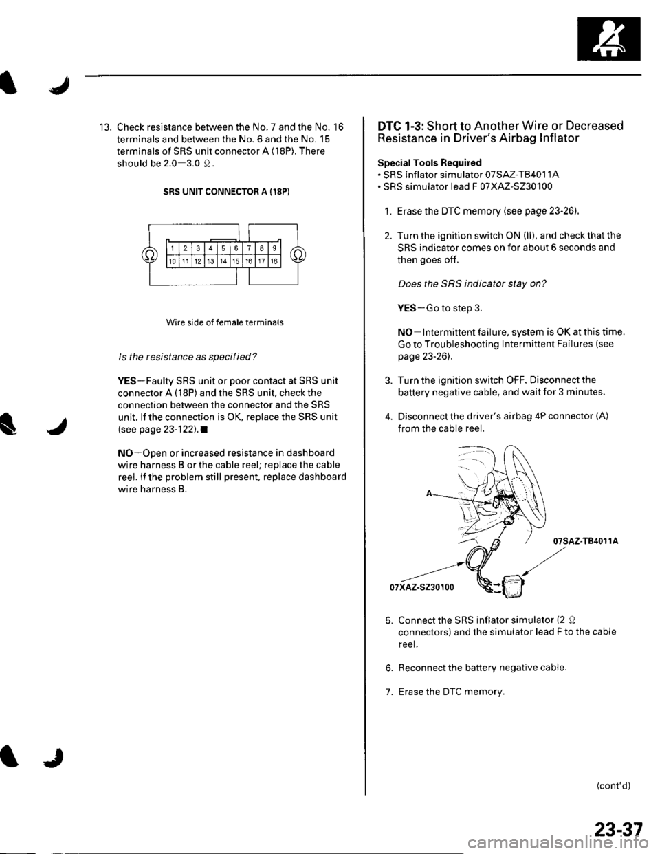
13. Check resistance between the No. 7 and the No. '16
terminals and between the No. 6 and the No. 15
terminals of SRS unit connector A (18P). There
should be 2.0 3.0 0.
SRS UNIT CONNECTOR A I18P)
Wire side of female terminals
ls the resistance as specilied?
YES-Faulty SRS unit or poor contact at SRS unit
connector A (18P) and the SRS unit, check the
connection between the connector and the SRS
unit. lf the connection is OK, replace the SRS unit
(see page 23-122).1
NO-Open or increased resistance in dashboard
wire harness B orthe cable reel; replace the cable
reel. lf the problem still present, replace dashboard
wire harness B.
DTC 1-3: Short to Another Wire or Decreased
Resistance in Driver's Airbag Inflator
SpecialTools Required. SRS inflator simulator 07SAZ-T8401 1A. SRS simulator lead F 07XAZ-S230100
1. Erasethe DTC memory (see page 23-26).
2. Turn the ignition switch ON (ll), and check that the
SRS indicator comes on for about 6 seconds and
then goes of{.
Does the SRS indicator stay on?
YES-Go to step 3.
NO Intermittent failure, system is OK at this time.
Go to Troubleshooting Intermittent Failures (see
page 23-261.
Turn the ignition switch OFF. Disconnect the
battery negative cable, and wait for 3 minutes,
Disconnect the driver's airbag 4P connector (A)
from the cable reel.
07sAz-T84011A
07xAz-s230100
Connectthe SRS inflator simulator {2 0
connectors) and the simulator lead F to the cable
reel.
Reconnect the battery negative cable.
Erase the DTC memory.1.
(cont'd)
23-37
Page 1045 of 1139
sRs
DTC Troubleshooting {cont'd)
8. Read the DTC.
Is DTC 1-3 indicated?
YES Go to step 9.
NO Short in the driver's airbag; replace the
driver's airbag (see page 23-'l 13).1
9. Turn the ignition switch OFF. Disconnect the
battery negative cable, and wait for 3 minutes.
10. Disconnect the front passenger's airbag 4P
connector from dashboard wire harness B (see step
3 on page 23-21).
1 '1. Disconnect both seat belt tensioner 2P connectors
from the floor wire harness (see step 5 on page 23-
22t.
12. Disconnect SRS unit connectorA (18P)from the
SRS unit (see step 7 on page 23-221.
13. Disconnectthe special tool from the cable reel.
23-38
IJ
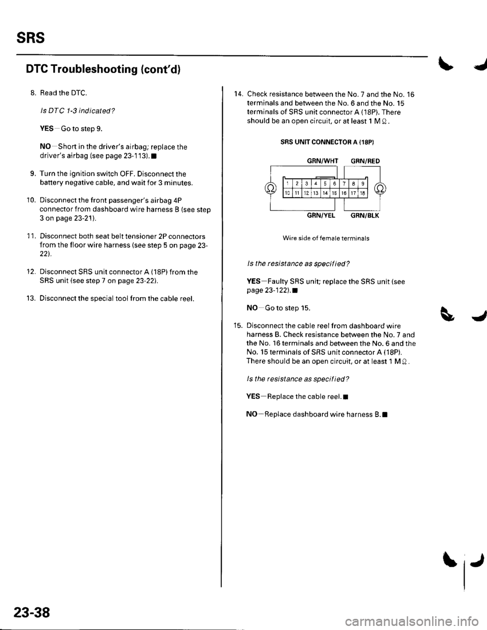
14. Check resistance between the No. 7 and the No. 16
terminals and between the No.6 and the No. 15
terminals of SRS unit connectorA (18P). There
should be an open circuit, or at least 1 M Q .
SRS UNIT CONNECTOR A {18P)
GRN/WHT GRN/RED
GRN/YELGRN/BLK
Wire side of female terminals
ls the rcsistance as specified?
YES Faulty SRS unit; replace the SRS unit (see
page 23-122],.a
NO Go to step 15.
Disconnect the cable reel from dashboard wire
harness B. Check resistance between the No,7 and
the No. 16 terminals and between the No. 6 and the
No. 15 terminals of SRS unit connector A (18P).
There should be an open circuit, or at least 1 M Q .
ls the resistance as specified?
YES Replace the cable reel.I
NO-Replace dashboard wire harness B.l
Page 1046 of 1139
s
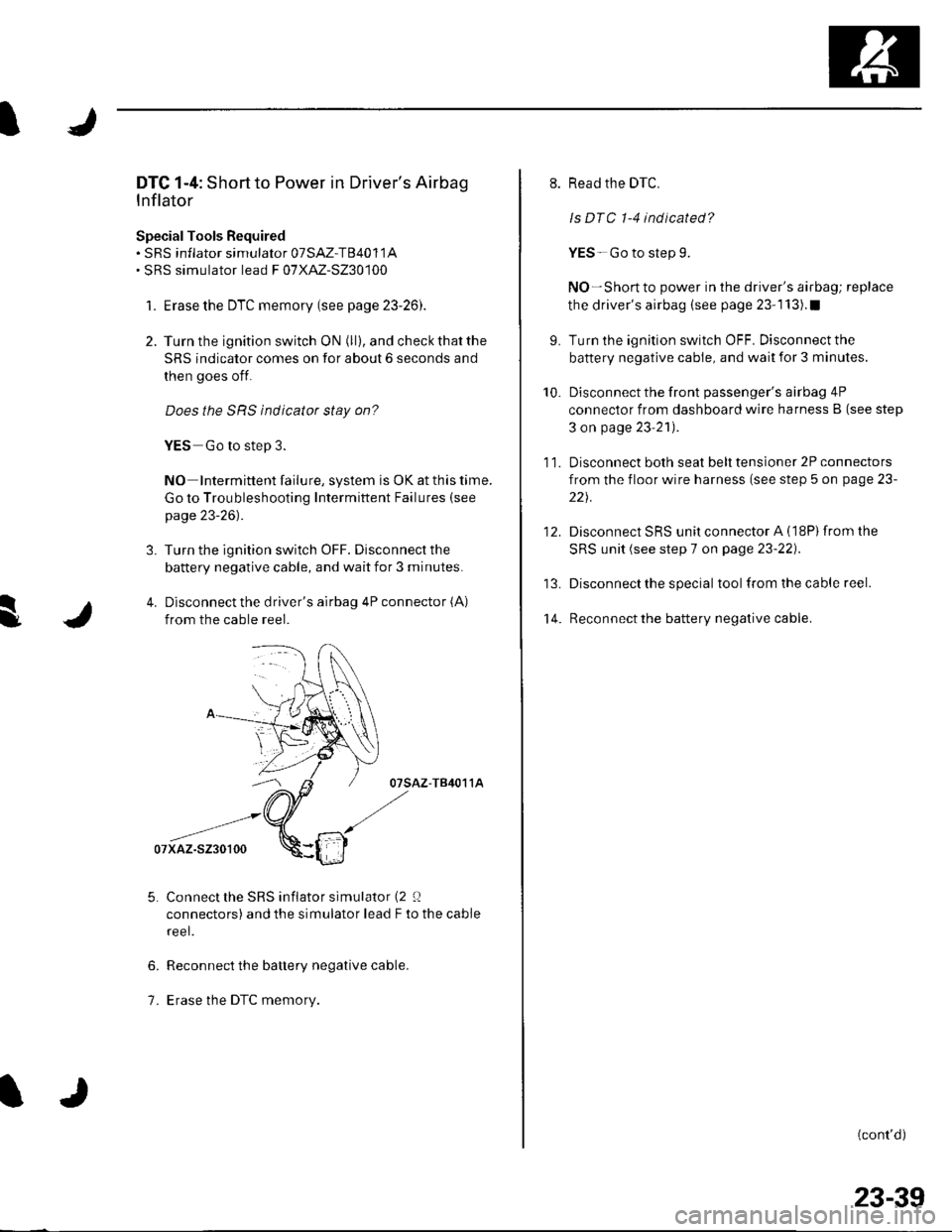
DTC 1-4: Short to Power in Driver's Airbag
Inflator
SpecialTools Bequired. sRS inflator simulator 07SAZ-T84011A. SRS simulator lead F 07XAZ-S230100
1. Erase the DTC memory (see page 23-26).
2. Turn the ignition switch ON (ll), and check that the
SRS indicator comes on for about 6 seconds and
then goes off.
Does the SRS indicator stay on?
YES Go to step 3.
NO Intermittent failure, system is OK at this time.
Go to Troubleshooting Intermittent Failures (see
page 23-26).
3. Turn the ignition switch OFF. Disconnect the
battery negative cable, and wait for 3 minutes.
4. Disconnect the driver's airbag 4P connector (A)
from the cable reel.
07sAz-T84011A
Connect the SRS inflator simulator (2 0
connectors) and the simulator lead F to the cable
reel.
Reconnect the battery negative cable.
Erase the DTC memory.
6.
1.
9.
10.
't 4.
11.
12.
Read the DTC.
ls DTC 1-4 indicated?
YES-Go to step 9.
NO-Short to power in the driver's airbag; replace
the driver's airbag (see page 23-1 13).1
Turn the ignition switch OFF. Disconnect the
battery negative cable, and wait for 3 minutes.
Disconnect the front passenger's airbag 4P
connector from dashboard wire harness B (see step
3 on page 23'21).
Disconnect both seat belt tensioner 2P connectors
from the floor wire harness (see step 5 on page 23-
221.
Disconnect SRS unit connector A (18P)from the
SRS unit (see step 7 on page 23-22).
Disconnect the special tool from the cable reel.
Reconnect the battery negative cable.
(cont'd)
23-39
Page 1047 of 1139
SRS
16.
DTC Troubleshooting (cont'd)
Turn the ignition switch ON {ll).
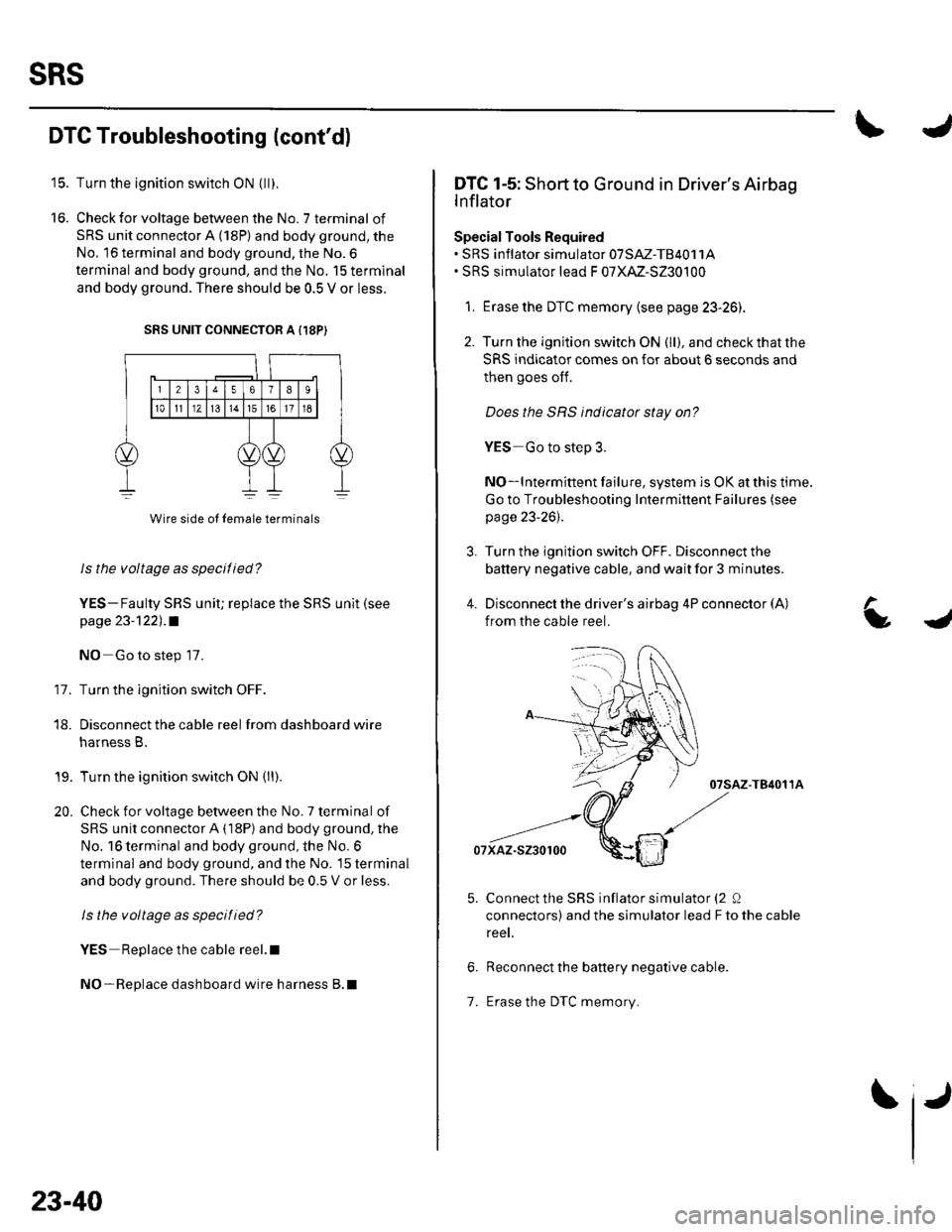
Check for voltage between the No. 7 terminal of
SRS unit connector A (18P) and body ground, the
No. 16 terminal and body ground, the No.6
terminal and body ground, and the No. 15 terminal
and body ground. There should be 0.5 V or less.
SRS UNIT CONNECTOR A {18P)
11.
Wire side ol lemale terminals
Is the voltage as specilied?
YES-Faulty SRS uniU replace the SRS unit (see
page 23-122) .a
NO Go to step 17.
Turn the ignition switch OFF.
Disconnect the cable reel from dashboard wire
harness B.
Turn the ignition switch ON (ll).
Check for voltage between the No. 7 terminal of
SRS unit connector A (18P) and body ground, the
No. 16 terminal and body ground, the No. 6
terminal and body ground, and the No. 15 terminal
and body ground. There should be 0.5 V or less.
ls the voltage as specitied?
YES Replace the cable reel.l
NO-Replace dashboard wire harness B.l
18.
19.
20.
23-40
1.
IJ
L
DTC 1-5: Short to Ground in Driver's Airbag
lnflator
Special Tools Required. SRS inflator simulator 07SM-TB4011A. SRS simulator lead F 07XM-S230100
1. Erase the DTC memory (see page 23-26).
2. Turn the ignition switch ON (ll), and checkthatthe
SRS indicator comes on for about 6 seconds and
then goes oIf.
Does the SBS indicator stay on?
YES Go to step 3.
NO-lntermittent failure, system is OK at this time.
Go to Troubleshooting Intermittent Failures (see
page 23-26).
3. Turn the ignition switch OFF. Disconnect the
battery negative cable, and wait for 3 minutes.
4. Disconnect the driver's airbag 4P connector (A)
from the cable reel.
07sAz-T84011A
07xaz-s230100
Connect the SRS inflator simulator (2 0
connectors) and the simulator lead F to the cable
reet.
Reconnect the battery negative cable.
Erase the DTC memory.
a